EP0542247B1 - Tintenbehälter, Aufzeichnungskopf und Aufzeichnungsgerät, die diesen Tintenbehälter benutzen - Google Patents
Tintenbehälter, Aufzeichnungskopf und Aufzeichnungsgerät, die diesen Tintenbehälter benutzen Download PDFInfo
- Publication number
- EP0542247B1 EP0542247B1 EP92119344A EP92119344A EP0542247B1 EP 0542247 B1 EP0542247 B1 EP 0542247B1 EP 92119344 A EP92119344 A EP 92119344A EP 92119344 A EP92119344 A EP 92119344A EP 0542247 B1 EP0542247 B1 EP 0542247B1
- Authority
- EP
- European Patent Office
- Prior art keywords
- ink
- container
- chamber
- porous material
- container according
- Prior art date
- Legal status (The legal status is an assumption and is not a legal conclusion. Google has not performed a legal analysis and makes no representation as to the accuracy of the status listed.)
- Expired - Lifetime
Links
Images


Classifications
-
- B—PERFORMING OPERATIONS; TRANSPORTING
- B41—PRINTING; LINING MACHINES; TYPEWRITERS; STAMPS
- B41J—TYPEWRITERS; SELECTIVE PRINTING MECHANISMS, i.e. MECHANISMS PRINTING OTHERWISE THAN FROM A FORME; CORRECTION OF TYPOGRAPHICAL ERRORS
- B41J2/00—Typewriters or selective printing mechanisms characterised by the printing or marking process for which they are designed
- B41J2/005—Typewriters or selective printing mechanisms characterised by the printing or marking process for which they are designed characterised by bringing liquid or particles selectively into contact with a printing material
- B41J2/01—Ink jet
- B41J2/17—Ink jet characterised by ink handling
- B41J2/175—Ink supply systems ; Circuit parts therefor
- B41J2/17503—Ink cartridges
- B41J2/17513—Inner structure
Definitions
- the present invention relates to an ink container which permits a required quantity to be taken out therefrom on demand and which is usable in writing device usable in various recording fields, to a recording head unit using the same and a recording apparatus using the same.
- liquid container In such a liquid container it is desired that the liquid is supplied from the container through a supply port of the container in an amount matching the amount taken out therefrom and also that liquid does not leak out of the container when liquid is not supplied out of the container.
- This desire is particularly significant in the case of an ink container for an ink jet recording system in which the recording is effected by the ejection of the ink from a recording head, particularly bearing in mind the influence on the image quality of the ink supply amount.
- an ink container of an ink cartridge 301 is filled substantially entirely with a porous material 303 which retains the ink. Adjacent one end of the porous material 303, there is provided an ink supply port 306, which is in communication with a recording head 305 through a supply pipe, and adjacent the other end, there is provided an air vent 304.
- the vacuum in the ink container is maintained by the capillary force provided by the porous material 303, so that the ink does not leak out through the ink supply port 306.
- the ink is retained in the porous material, the amount of the ink contained in the cartridge or the ink container is small, and in addition, the amount of non-usable ink is also large.
- Figure 16 shows examples of such a structure.
- a liquid container is used for an ink jet recording head unit an ink container 401, an overflow sump 404 and the recording head 405 communicate through a porous material 403.
- the liquid containing portion 401 does not include porous material, the volume efficiency can be increased.
- the liquid containing portion 401 constitutes a closed space with the exception of a hole 406 through which air replaces the liquid as the liquid is consumed, so that the vacuum in the container is maintained to retain the liquid in the container.
- the ink containers have to be provided with the overflow sump having a capacity sufficient to guarantee against the worst possible ambient conditions so as to assure safe use even if the air in the ink chamber expands due to changes of pressure, temperature or the like.
- ink leaking from the print head due to temperature change in the above-discussed mechanism can be prevented to a certain extent.
- the capacity of the sump 404 is small as compared with the capacity of the ink container 402
- the ink from the ink. container cannot be accommodated and ink leaks from the sump.
- there are significant limitations during use If the print head is directed downwardly during use thereof, there is no problem. If, however, the print head is positioned horizontally with less than half the ink remaining, ink supply is prevented due to the position of the hole 104, and therefore, positions of the container from which the ink can be efficiently used is limited.
- U.S. Patent No. 4,920.362 proposes a solution to the problem of the relation between capacities of the ink container and the sump.
- the ink container 201 is divided into three chambers 206, 207 and 208 by two partition walls 202a and 202b.
- the chambers 206, 207 and 208 communicate with each other through small diameter orifices 203a and 203b formed in the partition walls 202a and 202b.
- the bottom of the first chamber 206 communicates with an ink well 209 for supplying the ink to an ink droplet producer 205.
- the bottom of the third chamber 208 communicates with an overflow sump 211 communicating with the external air through a vent 204 through a drop pipe 210 and bubble creating orifice 203c thereof.
- ink corresponding to the amount consumed from the ink droplet producer 205 is supplied to the first chamber 206 from the second chamber 207 through the orifice 203a. Ink is supplied to the second chamber 207 from the third chamber 208 through the orifice 203b. As a result, the internal pressure of the third chamber 208 decreases. When the internal pressure reaches a threshold level, air is supplied to the third chamber 208 through the bubble producing orifice 203c, and therefore, the internal pressure of the third chamber 208, by which the internal pressures of the second and first chambers 207 and 206 are controlled, is automatically controlled.
- the internal pressure of the ink sump 211 increases due to a change in ambient conditions, ink flows into the overflow sump 211 through the ink droplet pipe 210, and therefore, ink does not leak out from the ink droplet producer 205. Since the ink is consumed from the chambers 208, 207 and 206 in the order named, the chamber influenced by the ambient condition is substantially only one of the chambers 206, 207 and 208. For this reason, the amount of overflow ink can be decreased, so that the capacity of the overflow sump can be reduced, thus increasing the volume efficiency of the entire container.
- the plural ink chambers communicate with each other through such small size orifices as to produce capillary force, and therefore, there is a liability that clogging will occur if the ink contains foreign matter or precipitates.
- the small diameter orifices have to have such a configuration that ink does not leak out through the outlet, that both of the air and the ink do not flow simultaneously therethrough and that the efficient ink supply is not impeded. Therefore, it involves the manufacturing difficulty.
- the vacuum of the ink container 201 is maintained by small size orifices 203a and 203b.
- the ink chamber 208 is filled with air, and a part of the ink in the ink chamber 207 is already used with a certain volume of the air existing in the ink chamber. If the ink container is then so inclined that the air in the ink chamber 207 and the air in the ink chamber 208 communicate with each other through the small chamber orifice 203B, the ink in the ink chamber 207 is, in effect, directly open to the ambient air with the result of incapability of maintain the negative pressure. Then, the ink leaks more easily through the recording head 205.
- EP-A-0393320 discloses an ink container according to the preamble of claim 1.
- an ink container comprising a series of chambers for containing ink, adjacent chambers communicating by means of a respective communication port, the chamber at one end of said series having an ink supply port for supplying ink to an ink jet head and the container being provided with an air vent communicating with ambient air, characterised in that the air vent is provided in the chamber at said one end of the series and the ink supply path through the series of chambers to the ink supply port is provided by porous material extending from the ink supply port through the communication ports to the chamber at the other end of the said series.
- the present invention also provides a recording unit in accordance with claim 18 and a recording apparatus in accordance with claim 20.
- An embodiment of the present invention provides an ink container, a recording head unit using the same and a recording apparatus using the same from which ink does not leak irrespective of changes in ambient condition changes or orientation during use.
- An embodiment of the present invention provides an ink container, a recording head unit using the same and a recording apparatus using the same in which the degree of latitude in orientation of the container during use is large.
- An embodiment of the present invention provides an ink container, a recording head unit and a recording apparatus in which the volume efficiency of the container is large.
- An embodiment of the present invention provides an ink container, a recording head unit using the same and a recording apparatus using the same in which manufacturing costs and manufacturing difficulty of the container are low.
- an ink container embodying the present invention plural chambers communicate with each other by way of a porous material, and therefore, no clogging with the foreign matter of the like should occur.
- Porous material is also disposed at the discharge outlet, and therefore, the container vacuum is properly controlled by the capillary force of the porous material. This permits stabilized retention and supply of the liquid.
- ink can be stably supplied, enabling stabilized high quality recording.
- Figure 1 is a partly broken perspective view of an ink container according to an embodiment of the present invention.
- Figure 2 is a longitudinal sectional view of the same ink container.
- the ink container is used with a recording head which ejects the ink to a recording material such as a sheet of paper.
- the recording head 5 may be a separate member which is mountable to the liquid container.
- the main body 1 of the container is provided with liquid supply material 3 made of porous material (such as sponge or the like) or fibrous material.
- the portion other than the liquid supply material 3 is divided into six chambers 6a, 6b, 6c, 6d and 6e by partition plates 2a, 2b, 2c, 2d and 2e which are formed integrally or separately with the main body 1. If the material of the container body 1 is a transparent material or the like, the remaining amount of the ink can be known.
- the adjacent chambers are in flow communication only through the liquid supply material 3.
- the recording head 5 is mounted on an outer surface of the front wall 1b having the supply port 1d of the container body and is supplied with ink through the supply port 1d.
- the spaces in the first chamber 6a which is an end chamber communicates with the ambience through an air vent 4.
- the supply port 1d permits ink supply from the liquid supply material to the recording head 5.
- the first chamber 6a which is an end chamber of the container body includes a liquid supply material 3 extending to the neighborhood of the supply port 1d except for the above-mentioned space and the supply port 1d for dispersing the ink, and includes the air vent 4 opened to the space.
- the plural chambers communicate by the extension of the liquid supply material.
- the air vent 4 is in the form of a tube extending to the middle of the space of the first chamber. Therefore, even if the ink is contained in the first chamber 6a having the air vent 4, the ink does not leak out irrespective of the orientation of the ink container unless the volume of the ink exceeds half the volume of the first chamber 6a.
- the volume of the ink overflowing into the first chamber 6a is determined only by the volume of the ink in the chamber (6d, for example) or chambers that contain both the ink and the air therein prior to the temperature rise.
- the volume of the first chamber 6a is determined such that it has a proper ratio relative to the ink volume in the second 6b and subsequent chambers that contain both the air and the ink, in consideration of the variation ranges of the temperature and pressure.
- a chamber having a supply port for supplying the liquid and a chamber in flow communication with the ambience is in flow communication only with the liquid supply material. For this reason, even if ambient conditions such as temperature or pressure or the like change the ink can be sufficiently supplied to the supply port without the liability of ink leakage.
- the latitude of the pose of the ink container is large under the condition that the ink moved to the chamber in flow communication with the ambience due to the external ambient condition can restore to the original state.
- the liquid supply material in this embodiment will suffice if it is stable relative to the liquid contained in the container, if it is capable of retaining the liquid by the meniscus formed therein and if it is capable of coupling the adjacent chambers for liquid and air communication.
- the material include a porous material such as sponge and fibrous material such as felt. From the standpoint of use efficiency of the ink, the porous material is preferable.
- the liquid supply material is preferably continuous for flow communication between the chamber in communication with the outside air and the chamber provided with the supply port. However, it is not necessarily formed integrally, and from the convenience in the manufacturing thereof, plural liquid supply materials connected are usable.
- the partition plates 2a - 2e may be separate members from the main body of the container, but the hermetical sealing is desirably established to prevent the flow communication between adjacent chambers except through the liquid supply material 3.
- the number of chambers is desirable. From the standpoint of the stabilized supply of the liquid, the plural chambers are connected in series by the liquid supply material.
- the use of plural chambers permits consumption of the ink sequentially from the chamber having the air vent. Therefore, if at least a part of the container is made of transparent or semi-transparent material, the ink in the container can be observed to be aware of the remaining amount of the ink.
- Figure 3 is a schematic sectional view of an ink container according to a second embodiment of the present invention.
- a liquid supply member 13 extends to between an open end of a fifth partition plate 12e and a bottom wall 11a of the container body. But, there is no liquid supply member at a position facing the sixth chamber 6f of the bottom wall 11a.
- this embodiment is the same as the first embodiment.
- this embodiment is the same as in the first embodiment except that when the container is positioned such that the discharge port 11d faces upwardly during the printing, the ink remains in the sixth chamber 6f. Except for this positioning, the remaining amount of the ink can be reduced as compared with the first embodiment, corresponding to the less volume of the liquid supply member 13.
- the container may be in the form of an ink container cartridge separable from the recording head. Such embodiments will be described.
- FIG. 5 is a schematic view of an ink container according to a third embodiment of the present invention.
- the discharge port 21d formed in the front wall 21b of the container main body 21 is enclosed by a valve guide 29 projected inwardly.
- An open end of the valve guide 29 is covered with a porous material 23, and the discharge port 21d is closed by a ball 28 normally urged to the discharge port 21d by a spring 27.
- the discharge port 21d is opened by a part of the recording head to be supplied with the ink from the container, upon container therebetween.
- Figure 6 shows an ink container according to a fourth embodiment of the present invention.
- the discharge port 31d of the container body 31 is closed by a ball 38 normally urged to the discharge port 31d by the liquid supply material disposed adjacent to the discharge port 31d.
- FIG. 7 shows an ink container according to a fifth embodiment of the present invention.
- the discharge port 41d of the container 41 is closed by a closing sheet 48, which is peeled off or torn by a ink receipt of unshown recording head, upon start of use, to permit the ink supply therefrom.
- a container body 51a has a liquid supply material 53a of the same material at the same position as in the foregoing embodiments. This is operable in all positions except for the upside down position in Figure 8, that is, the position in which the liquid supply material 53a is at the top.
- Figure 8B shows a liquid container body 51b having a liquid supply material 53b rotated by 90 degrees from Figure 8A position. This is operable except for the position in which the left side is at the bottom.
- Figure 8C shows a container body 51c having an L-shaped liquid supply material 53c. This is operable in any position.
- Figure 8D shows a container body 51d having a channel shaped liquid supply material 53d. This is operable in any position.
- Figure 9A shows an example having a rod-like liquid supply material 63a at a corner of the container body 61a.
- Figure 9B shows an example having a rod-like liquid supply material 63b at a central portion of a wall of the container body.
- Figure 9C shows an example having rod-like liquid supply materials at two corners of a wall of the container body 61c. It is operable in any position.
- a surface indicated as being the bottom surface of the container body 71a is inclined, and along the inclined surface, the liquid supply material 73a is disposed.
- a surface of the container body 71b which is indicated as being the bottom surface and the right side surfaces are inclined surfaces, and at the corner, the liquid supply material 73b of triangular column shape is disposed.
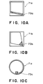
- the container body 71c is cylindrical, and the liquid supply material 73c is disposed on the inside surface thereof.
- Figures 11A, 11B and 11C show sectional views of an ink container included for illustrative purposes.
- the liquid supply member is extended to the top along each of partition walls. Then, even when the ink container becomes upside-down, the porous material or the fibrous material extended along the partition walls absorbs the ink, and therefore, the ink can be used up.
- the number of chambers is 6.
- the chamber having the air vent 4 does not contain the ink in the initial state, the size of that chamber has to be increased to prevent leakage, if the number of chambers is small, and therefore, the ink capacity is not very large. If the number of chambers is too large, the volume occupied by the partition walls decreases with the result of low ink capacity, again. In consideration of these factors, the number of the chambers is properly determined by one skilled in the art.
- the volume of each of the chambers may be any, but it is preferable that the chamber having the air vent has a volume which is not less than 0.6 times the volume of the maximum volume chamber. This is because the ink leakage has to be assuredly prevented even when the air in the container expands or contracts as a result of temperature change or pressure change which possibly occurs under the normal ink container use or handling (the pressure in the cargo chamber is approx. 0.7 atom).
- the size of the chambers are preferably uniform or may be increased toward the supply port.
- At least portions of the liquid supply material (porous material or fibrous material) which are under the partition walls preferably have substantially isotropic easiness in the ink seeping.
- the preferable porous material constituting the liquid supply material 3 is polyurethane foam material.
- polyether polyol, polyisocyanate and water are reacted with foaming material, catalyst, coloring agent or additives, if desired, by which a high polymer material having a great number of pores is produced. This is cut into desired size (block), and the block is immersed in the ambience of flammable gas. By explosion of the gas, the film materials between the cells is removed.
- This producing method is preferable for the material used in this invention.
- Table 1 shows results of evaluation of various necessary properties of respective ink containers having the porous material (polyether polyurethane foam) having various porosities.
- the ink containers evaluated are those of Figure 2 embodiment.
- the porous material continuously extends from the first chamber to the sixth chamber, and is packed between the bottom surfaces of the partition plates 2a - 2e and the bottom surface of the container 1 without clearance therebetween.
- the packing degree is expressed as a ratio T2/T1 (compression ratio: K), where T1 is a distance between the inside bottom surface 1s of the ink container and the bottom surface of the partition plate 2a - 2e, and T2 is a thickness of the porous material before insertion therebetween.
- the ratio K larger than 1 means the porous material is compressed between the partition plate and the bottom of the ink container, whereas the ratio smaller than 1 means existence of a gap between the porous material and the partition plate or the bottom surface of the ink container. In the latter case, the problem will arise, as will be described hereinafter.
- the ratio K is 0.8 at the bottom of the partition plate 1a, for example, a gap exists between the partition plate 1a and the bottom surface of the ink container, and therefore, the reverse flows of the air and the ink occur, that is, the air flow from the first chamber 6a to the second chamber 6b, and the ink flow from the second chamber 1b to the first chamber 1a. If the ambient condition particularly the temperature rise occurs under this condition, the air expands, and the amount of the ink corresponding to the air expansion moves from the second chamber 1b to the first chamber 6a. If, however, the first chamber already contains the ink, the first chamber comes to contain a sum of the ink, with the possible result that the sum of the ink amount exceeds the capacity of the first chamber, which leads to the leakage of the ink through the air vent 4.
- the porosity P means a number of cells in 1 inch of the porous material.
- the compression ratio K was 1.5, while the porosity of the porous material was changed, and the porous materials are evaluated in response of ink supply and durability against vibration.
- "non-compression” means the portion of the porous material where it is not compressed, and it is 7 times as large as the portion which is sandwiched between the partition plate and the bottom plate, as measured in the direction of the ink flow.
- the recording head had 60 nozzles each ejects approx. 100 pl, which was operated at the ejection frequency of 4 kHz. All of the 60 nozzles were actuated (solid image printing). In the evaluation tests, when 10 A4 size sheets were recorded, the evaluation was "G”, and when ejection failure occurs before 10 sheets were completed, the evaluation was "N".
- the ink container connected with the same recording head was positioned vertically with the recording head at the bottom, and was vibrated at 2 G/10 Hz for 1 hour.
- the evaluation was "G”
- the evaluation was "N”.
- the air vent was the one directly opening the first chamber 1a to the ambience.
- the quantity of pores (per inch) is preferably 135 - 270.
- the consideration is paid to the flow passage below the partition plate as follows. If the cross-sectional area of the flow passage before being filled with the porous or fibrous material between adjacent ink chambers, is too large, the air can remain with the result that the once formed air path is not easily filled back with the ink.
- the porous material or the fibrous material which are available these days, are considered as an aggregate having various different capillary tubes, if seen microscopically. Therefore, if the cross-sectional area is too small, the difference appears as it is in the difference of the vacuum in the ink supply container. Therefore, the cross-sectional area is preferably approx. 1 - 100 mm 2 . However, this is not limiting if the variation of the capillary tubes of the porous material or the fibrous materials are hardly observed.
- Such an edge of the partition plate as being press-contacted to the porous material or the fibrous materials (aggregate) and the other portion enclosing the porous material may be flat surface or may be provided with small projections. As a further alternative, the surfaces may be roughened. By doing so, unintended movement of the porous material or the fibrous material pressed, can be avoided.
- the description will be made as to the mounting means for mounting the liquid container according to this invention and the position or pose confining means.
- the liquid container of this invention is indicated by a reference numeral 1. It comprises an air vent 4, a supply port 5 and an operating position confining or regulating portion 19.
- the internal structure of the container is as disclosed in each of the above-described embodiments.
- An element 6 receives the liquid from the liquid container through the supply port 5.
- the element 6 is a recording head.
- the recording head is provided with positioning means for regulating the position of the liquid container.
- Mounting means 22 is also provided with positioning means for correctly positioning the liquid container.
- the liquid container of this invention is operable in almost any pose of the container, but for the purpose of most stable liquid supply, the liquid supply material is preferably at the bottom.
- the positioning portions are effective.
- the position or pose of the liquid container may be determined by the cooperation between the positioning portion of the recording head and the positioning portion of the container. Otherwise, the positioning portion of the mounting means and the positioning portion of the container may be cooperatively used.
- the recording head and the ink container according to any one of the embodiments of the present invention are joined so as to constitute a recording head unit.
- the recording head unit is carried on a cartridge 101 which is guided by a guiding shaft 104 and a leak screw 105 having a helical groove 105a.
- the ink container according to this invention may be mountable to the recording head.
- the recording head 103 is provided with a pipe or rod not shown, and when the ink container cassette is mounted, the pipe or rod 7 is inserted into the discharge port of the container to open the discharge port against the spring force of the spring 6 to the ball 5.
- the recording head is driven in response to a signal supply means in the recording apparatus.
- the lead screw 105 is rotated in the forward and backward directions by a reversible motor 106 through gear trains 106a, 106b, 106c and 106d.
- the carriage 101 is reciprocated in the direction indicated by an arrow and in the opposite direction through an unshown pin of the cartridge 101, the end portion of the pin being in engagement with the helical groove 105a.
- the switching between the forward rotation and the backward rotation of the driving motor 106 is effected in response to detection of the home position of the carriage 101, which is detected by a combination of a lever 115 of the cartridge 101 and a photocoupler 116.
- the recording material in the form of a sheet of paper 109 is contacted to a platen 107 by a confining plate 108, and is faced to the recording head by an unshown sheet feeding roller driven by a sheet feeding motor 110.
- a recovery unit 111 functions to remove foreign matter deposited on the ejection outlet side of the recording head 103 or viscosity increased ink thereon so as to recover the regular ejection performance.
- the recovery unit 111 comprises a capping member 113 in communication with an unshown sucking means and sucks the ink through the ejection outlets of the recording head 103 which is capped to remove the foreign matter and the viscosity increased ink from the neighborhood of the ejection outlets.
- a cleaning blade which is movable toward and away from the movement path of the ejection outlet side of the recording head 103, along a guiding member 112. A free end of the cleaning blade 114 is effective to remove the foreign matter and ink droplets deposited on the ejection outlet side surface of the recording head.
- the present invention is particularly suitably usable in an ink jet recording head and recording apparatus wherein thermal energy by an electrothermal transducer, laser beam or the like is used to cause a change of state of the ink to eject or discharge the ink. This is because the high density of the picture elements and the high resolution of the recording are possible.
- the typical structure and the operational principle are preferably the ones disclosed in U.S. Patent Nos. 4,723,129 and 4,740,796.
- the principle and structure are applicable to a so-called on-demand type recording system and a continuous type recording system.
- it is suitable for the on-demand type because the principle is such that at least one driving signal is applied to an electrothermal transducer disposed on a liquid (ink) retaining sheet or liquid passage, the driving signal being enough to provide such a quick temperature rise beyond a departure from nucleation boiling point, by which the thermal energy is provided by the electrothermal transducer to produce film boiling on the heating portion of the recording head, whereby a bubble can be formed in the liquid (ink) corresponding to each of the driving signals.
- the liquid (ink) is ejected through an ejection outlet to produce at least one droplet.
- the driving signal is preferably in the form of a pulse, because the development and contraction of the bubble can be effected instantaneously, and therefore, the liquid (ink) is ejected with quick response.
- the driving signal in the form of the pulse is preferably such as disclosed in U.S. Patents Nos. 4,463,359 and 4,345,262.
- the temperature increasing rate of the heating surface is preferably such as disclosed in U.S. Patent No. 4,313,124.
- the structure of the recording head may be as shown in U.S. Patent Nos. 4,558,333 and 4,459,600 wherein the heating portion is disposed at a bent portion, as well as the structure of the combination of the ejection outlet, liquid passage and the electrothermal transducer as disclosed in the above-mentioned patents.
- the present invention is applicable to the structure disclosed in Japanese Laid-Open Patent Application No. 123670/1984 wherein a common slit is used as the ejection outlet for plural electrothermal transducers, and to the structure disclosed in Japanese Laid-Open Patent Application No. 138461/1984 wherein an opening for absorbing pressure wave of the thermal energy is formed corresponding to the ejecting portion. This is because the present invention is effective to perform the recording operation with certainty and at high efficiency irrespective of the type of the recording head.
- the present invention is effectively applicable to a so-called full-line type recording head having a length corresponding to the maximum recording width.
- a recording head may comprise a single recording head and plural recording head combined to cover the maximum width.
- the present invention is applicable to a serial type recording head wherein the recording head is fixed on the main assembly, to a replaceable chip type recording head which is connected electrically with the main apparatus and can be supplied with the ink when it is mounted in the main assembly, or to a cartridge type recording head having an integral ink container.
- the provisions of the recovery means and/or the auxiliary means for the preliminary operation are preferable, because they can further stabilize the effects of the present invention.
- preliminary heating means which may be the electrothermal transducer, an additional heating element or a combination thereof.
- means for effecting preliminary ejection (not for the recording operation) can stabilize the recording operation.
- the recording head mountable may be a single corresponding to a single color ink, or may be plural corresponding to the plurality of ink materials having different recording color or density.
- the present invention is effectively applicable to an apparatus having at least one of a monochromatic mode mainly with black, a multi-color mode with different color ink materials and/or a full-color mode using the mixture of the colors, which may be an integrally formed recording unit or a combination of plural recording heads.
- the most effective one for the ink materials described above is the film boiling system.
- the ink jet recording apparatus may be used as an output terminal of an information processing apparatus such as computer or the like, as a copying apparatus combined with an image reader or the like, or as a facsimile machine having information sending and receiving functions.
- the plural chambers communicate with each other only through a continuous liquid supply material, and therefore, the latitude of the workable position of the liquid container is high without ink leakage due to the ambient condition change or due to the position change.
- the ink supply is stabilized, and the ink capacity is large as compared with the size of the container, and therefore, the size of the ink container can be reduced.
- liquid supply material functions also as a filter, and therefore, the flow passage is protected from clogging.
- a small size recording apparatus can be provided with stable recording operation.
- the liquid container can be produced without difficulty, because precision machining (drilling or the like) is not required.
Landscapes
- Ink Jet (AREA)
- Recording Measured Values (AREA)
- Details Of Rigid Or Semi-Rigid Containers (AREA)
- Table Devices Or Equipment (AREA)
- Containers And Packaging Bodies Having A Special Means To Remove Contents (AREA)
Claims (20)
- Tintenbehälter, der eine Reihe von Kammern (6a, 6b, 6c, 6d, 6e, 6f) aufweist, die Tinte enthalten, bei welchem angrenzende Kammern mit Hilfe einer entsprechenden Verbindungsöffnung in Verbindung stehen, bei welchem die Kammer (6a) an einem Endabschnitt der Reihe eine Tintenzuführungsöffnung (1d) zur Zufuhr von Tinte zu einem Tintenstrahlkopf aufweist und der Behälter mit einer Entlüftungsöffnung (4) versehen ist, die mit der Umgebungsluft in Verbindung steht,
dadurch gekennzeichnet, daß die Entlüftungsöffnung (4) in der Kammer an dem einen Endabschnitt der Reihe vorgesehen ist und der Tintenzuführungsweg durch die Reihe von Kammern (6a, 6b, 6c, 6d, 6e, 6f) zu der Tintenzuführungsöffnung (1d) mittels porösen Materials (3) geschaffen ist, das sich von der Tintenzuführungsöffnung (1d) durch die Verbindungsöffnungen zu der Kammer (6f) an dem anderen Endabschnitt der Reihe erstreckt. - Behälter gemäß Anspruch 1, bei welchem die Zuführungsöffnung (1d) in einer Wand des Behälters vorgesehen ist, die eine Fläche der einen Endkammer (6a) ausbildet, die einer Wand des Behälters gegenüberliegt, die eine Fläche der anderen Endkammer (6f) ausbildet.
- Behälter gemäß Anspruch 1 oder 2, bei welchem zwischen der Entlüftungsöffnung (4) und dem porösen Material (3) ein Raum vorgesehen ist.
- Behälter gemäß Anspruch 3, bei welchem die Entlüftungsöffnung (4) die Form einer Röhre hat, die sich in den Raum innerhalb der einen Endkammer (6a) erstreckt.
- Behälter gemäß Anspruch 1, 2, 3 oder 4, bei welchem sich das poröse Material (3) durch alle Kammern (6a, 6b, 6c, 6d, 6e, 6f) erstreckt.
- Behälter gemäß Anspruch 1, 2, 3 oder 4, bei welchem sich das poröse Material (3) von der einen Endkammer (6a) nur bis zu der Verbindungsöffnung der anderen Endkammer (6f) erstreckt.
- Behälter gemäß einem der vorhergehenden Ansprüche, bei welchem die Zuführungsöffnung (21d) mittels einer Kugel (28, 38) geschlossen ist, die vor der Benutzung des Behälters in Richtung auf die Zuführungsöffnung vorgespannt wird.
- Behälter gemäß Anspruch 7, bei welchem die Kugel in einer Ventilführung (28) aufgenommen ist, die sich derart in die eine Endkammer erstreckt, daß sie an dem porösen Material (23) anliegt, und mittels einer Feder (27) in Richtung auf die Zuführungsöffnung (21d) vorgespannt ist.
- Behälter gemäß einem der Ansprüche 1 bis 6, bei welchem die Zuführungsöffnung (41d) vor der Benutzung mittels eines entfernbaren Verschlußstreifens (48) geschlossen ist.
- Behälter gemäß einem der vorhergehenden Ansprüche, bei welchem der Behälter im Querschnitt vier Seiten hat und sich das poröse Material fortlaufend entlang einer, zwei oder drei Seiten des Querschnitts erstreckt.
- Behälter gemäß einem der Ansprüche 1 bis 9, bei welchem der Behälter im Querschnitt vier Seiten hat und das poröse Material als ein Stab aus porösem Material vorgesehen ist, der in einer Ecke oder in der Mitte einer Seite des Querschnitts positioniert ist.
- Behälter gemäß einem der Ansprüche 1 bis 9, bei welchem der Behälterkörper die Form eines Zylinders hat und sich das poröse Material (73c) axial entlang eines Teils der Innenfläche des Zylinders erstreckt.
- Behälter gemäß einem der vorhergehenden Ansprüche, bei welchem sich das poröse Material (3, 23, 33, 43) von der Wand der einen Endkammer (6a) angrenzend der Verbindungsöffnung durch die Kammer in Richtung auf die Entlüftungsöffnung (4) erstreckt.
- Behälter gemäß einem der vorhergehenden Ansprüche, bei welchem das poröse Material die Form eines einstückigen Elements hat.
- Behälter gemäß einem der vorhergehenden Ansprüche, bei welchem ein Hauptkörper des Behälters aus einem Material ausgebildet ist, das die Beobachtung von Tinte in diesem gestattet.
- Behälter gemäß einem der vorhergehenden Ansprüche, bei welchem das poröse Material durch faserartiges Material ersetzt ist.
- Behälter gemäß einem der vorhergehenden Ansprüche, bei welchem das poröse Material (3) die Tintenzuführungsöffnung abdeckt.
- Aufzeichnungskopfeinheit, die einen Tintenbehälter in Übereinstimmung mit einem der vorhergehenden Ansprüche und einen Aufzeichnungskopf (6) aufweist, der eine Energieerzeugungseinrichtung zur Erzeugung von Energie hat, um diesem aus der Zuführungsöffnung (1d) zugeführte Tinte auszustoßen.
- Aufzeichnungskopfeinheit gemäß Anspruch 18, bei welcher der Tintenbehälter abnehmbar an dem Aufzeichnungskopf befestigbar ist.
- Aufzeichnungsvorrichtung, die einen Tintenbehälter gemäß einem der Ansprüche 1 bis 18, einen Aufzeichnungskopf (6), der eine Energieerzeugungseinrichtung zur Erzeugung von Energie hat, um aus der Zuführungsöffnung des Tintenbehälters zugeführte Tinte auszustoßen, und eine Einrichtung zur Zuführung von elektrischer Energie zu der Energieerzeugungseinrichtung aufweist.
Priority Applications (1)
| Application Number | Priority Date | Filing Date | Title |
|---|---|---|---|
| EP97203070A EP0829366B1 (de) | 1991-11-12 | 1992-11-12 | Flüssigkeitsbehälter für Aufzeichnungskopf und Aufzeichnungsgerät damit versehen |
Applications Claiming Priority (2)
| Application Number | Priority Date | Filing Date | Title |
|---|---|---|---|
| JP3323906A JP2960235B2 (ja) | 1991-11-12 | 1991-11-12 | インク容器、これを用いた記録ヘッドユニットおよびこれを搭載する記録装置 |
| JP323906/91 | 1991-11-12 |
Related Child Applications (1)
| Application Number | Title | Priority Date | Filing Date |
|---|---|---|---|
| EP97203070A Division EP0829366B1 (de) | 1991-11-12 | 1992-11-12 | Flüssigkeitsbehälter für Aufzeichnungskopf und Aufzeichnungsgerät damit versehen |
Publications (3)
| Publication Number | Publication Date |
|---|---|
| EP0542247A2 EP0542247A2 (de) | 1993-05-19 |
| EP0542247A3 EP0542247A3 (en) | 1993-08-25 |
| EP0542247B1 true EP0542247B1 (de) | 1998-06-10 |
Family
ID=18159938
Family Applications (2)
| Application Number | Title | Priority Date | Filing Date |
|---|---|---|---|
| EP92119344A Expired - Lifetime EP0542247B1 (de) | 1991-11-12 | 1992-11-12 | Tintenbehälter, Aufzeichnungskopf und Aufzeichnungsgerät, die diesen Tintenbehälter benutzen |
| EP97203070A Expired - Lifetime EP0829366B1 (de) | 1991-11-12 | 1992-11-12 | Flüssigkeitsbehälter für Aufzeichnungskopf und Aufzeichnungsgerät damit versehen |
Family Applications After (1)
| Application Number | Title | Priority Date | Filing Date |
|---|---|---|---|
| EP97203070A Expired - Lifetime EP0829366B1 (de) | 1991-11-12 | 1992-11-12 | Flüssigkeitsbehälter für Aufzeichnungskopf und Aufzeichnungsgerät damit versehen |
Country Status (11)
| Country | Link |
|---|---|
| US (1) | US5805188A (de) |
| EP (2) | EP0542247B1 (de) |
| JP (1) | JP2960235B2 (de) |
| KR (1) | KR970007633B1 (de) |
| CN (1) | CN1030051C (de) |
| AT (2) | ATE213696T1 (de) |
| AU (2) | AU2829792A (de) |
| CA (1) | CA2082545E (de) |
| DE (2) | DE69232449T2 (de) |
| MY (1) | MY112556A (de) |
| TW (1) | TW227600B (de) |
Families Citing this family (55)
| Publication number | Priority date | Publication date | Assignee | Title |
|---|---|---|---|---|
| US6145974A (en) * | 1983-10-13 | 2000-11-14 | Seiko Epson Corporation | Ink-supplied printer head and ink container |
| US6247803B1 (en) | 1983-10-13 | 2001-06-19 | Seiko Epson Corporation | Ink jet recording apparatus and method for replenishing ink in the tank cartridge |
| US6276785B1 (en) | 1983-10-13 | 2001-08-21 | Seiko Epson Corporation | Ink-supplied printer head and ink container |
| JP3513979B2 (ja) * | 1994-09-16 | 2004-03-31 | セイコーエプソン株式会社 | インクジェットプリンタ用インクカートリッジ |
| US6474798B1 (en) | 1984-10-11 | 2002-11-05 | Seiko Epson Corporation | Ink supplied printer head and ink container |
| US6332675B1 (en) | 1992-07-24 | 2001-12-25 | Canon Kabushiki Kaisha | Ink container, ink and ink jet recording apparatus using ink container |
| JP3043926B2 (ja) * | 1993-08-20 | 2000-05-22 | キヤノン株式会社 | インクカートリッジ |
| CA2101017C (en) * | 1992-07-24 | 1999-10-26 | Masahiko Higuma | Ink jet cartridge, ink jet head and printer |
| US6467890B1 (en) | 1993-06-29 | 2002-10-22 | Canon Kabushiki Kaisha | Partitioned ink tank |
| JP3143539B2 (ja) * | 1993-02-03 | 2001-03-07 | キヤノン株式会社 | インク残量検知方法およびその装置ならびにインクジェット記録装置 |
| DE69417468T2 (de) | 1993-05-13 | 1999-10-28 | Canon Kk | Tintenbehälter, Druckkopfkassette und Tintenstrahldrucker |
| US6286944B1 (en) | 1993-05-21 | 2001-09-11 | Canon Kabushiki Kaisha | Ink jet unit with cartridge having controlled ink flow |
| ATE187930T1 (de) * | 1993-05-21 | 2000-01-15 | Canon Kk | Tintenstrahleinheit |
| SG67330A1 (en) * | 1993-06-29 | 1999-09-21 | Canon Kk | An ink tank unit an ink jet cartridge having said ink tank unit and an ink jet apparatus having said ink jet cartridge |
| US6206514B1 (en) * | 1993-06-29 | 2001-03-27 | Canon Kabushiki Kaisha | Ink tank unit, an ink jet cartridge having said ink tank unit and an ink jet apparatus having said ink jet cartridge |
| JP3133906B2 (ja) * | 1993-08-19 | 2001-02-13 | キヤノン株式会社 | インクタンクカートリッジ |
| CN1060115C (zh) * | 1993-08-23 | 2001-01-03 | 佳能株式会社 | 可更换的墨水盒 |
| US5790157A (en) * | 1993-08-31 | 1998-08-04 | Canon Kabushiki Kaisha | Ink filling method and apparatus for ink cartridge |
| US5971530A (en) * | 1993-10-27 | 1999-10-26 | Canon Kabushiki Kaisha | Refillable, evaporation-suppressing liquid container |
| US6238042B1 (en) | 1994-09-16 | 2001-05-29 | Seiko Epson Corporation | Ink cartridge for ink jet printer and method of charging ink into said cartridge |
| JP3245053B2 (ja) * | 1995-06-13 | 2002-01-07 | キヤノン株式会社 | インクタンク、該インクタンクの製造方法、前記インクタンクを用いるインクジェットカートリッジ及びインクジェット記録装置 |
| JP3315589B2 (ja) * | 1995-06-21 | 2002-08-19 | キヤノン株式会社 | インクタンク及びこれを備えた記録装置 |
| US6168266B1 (en) | 1995-09-29 | 2001-01-02 | Canon Kabushiki Kaisha | Ink tank cartridge, a manufacturing method thereof and a packaging structure of the ink tank cartridge |
| US5975687A (en) * | 1995-11-06 | 1999-11-02 | Lexmark International, Inc. | Insertable baffle for an ink supply reservoir |
| JP3245088B2 (ja) * | 1996-07-01 | 2002-01-07 | キヤノン株式会社 | 液体吐出ヘッドカートリッジ及び該カートリッジに用いられる液体収容容器 |
| JP3332779B2 (ja) * | 1996-07-31 | 2002-10-07 | キヤノン株式会社 | インクジェット記録装置用液体収納容器 |
| JP3880232B2 (ja) | 1997-12-25 | 2007-02-14 | キヤノン株式会社 | 液体供給方法、該液体供給方法を用いる液体供給システム、インクタンク |
| US6270207B1 (en) | 1998-03-30 | 2001-08-07 | Brother Kogyo Kabushiki Kaisha | Ink cartridge and remaining ink volume detection method |
| EP0947328B1 (de) * | 1998-03-30 | 2005-12-07 | Brother Kogyo Kabushiki Kaisha | Tintenpatrone und Verfahren zur Detektion der restlichen Tintenmenge |
| US6095643A (en) * | 1998-05-07 | 2000-08-01 | Lexmark International, Inc. | Refillable disposable inkjet cartridge with foam-filled and free ink reservoirs |
| EP1016533B3 (de) * | 1998-07-15 | 2011-08-31 | Seiko Epson Corporation | Tintenzufuhreinheit |
| US7383727B2 (en) * | 1999-05-20 | 2008-06-10 | Seiko Epson Corporation | Liquid cotainer having a liquid consumption detecting device therein |
| JP2001063089A (ja) | 1999-08-30 | 2001-03-13 | Canon Inc | インクタンク、記録ヘッドカートリッジおよびインクジェット記録装置 |
| JP3809401B2 (ja) | 2001-07-27 | 2006-08-16 | キヤノン株式会社 | インクタンク |
| JP2003112434A (ja) * | 2001-10-09 | 2003-04-15 | Bridgestone Corp | インク供給部材 |
| DE10206696B4 (de) * | 2002-02-18 | 2006-01-26 | Pelikan Hardcopy Production Ag | Tintenpatrone mit Ventil |
| US6837921B2 (en) * | 2002-03-12 | 2005-01-04 | Canon Kabushiki Kaisha | Ink tank |
| KR100840941B1 (ko) * | 2002-12-11 | 2008-06-24 | 삼성전자주식회사 | 휴대용 컴퓨터 |
| US20070035596A1 (en) * | 2005-08-10 | 2007-02-15 | Lexmark International, Inc. | Ink jet cartridge |
| US7399074B2 (en) * | 2005-09-30 | 2008-07-15 | Lexmark International, Inc. | Ink tank for a printhead |
| DE102006003055B4 (de) * | 2006-01-20 | 2008-02-07 | Phoenix Contact Gmbh & Co. Kg | Tintentank |
| JP5293243B2 (ja) * | 2008-03-24 | 2013-09-18 | セイコーエプソン株式会社 | 液体容器およびその製造方法 |
| WO2011159285A1 (en) | 2010-06-15 | 2011-12-22 | Hewlett-Packard Development Company, L.P. | Ink supply reservoir |
| JP6308989B2 (ja) | 2015-09-30 | 2018-04-11 | キヤノン株式会社 | 液体収納容器及び液体吐出装置 |
| JP6602160B2 (ja) | 2015-10-30 | 2019-11-06 | キヤノン株式会社 | 液体吐出装置及びヘッド |
| JP6611564B2 (ja) | 2015-10-30 | 2019-11-27 | キヤノン株式会社 | 液体収納ボトルおよび液体収納ボトルのパッケージ |
| JP2017081083A (ja) | 2015-10-30 | 2017-05-18 | キヤノン株式会社 | 液体吐出装置、ヘッド及び液体充填方法 |
| JP6700719B2 (ja) | 2015-10-30 | 2020-05-27 | キヤノン株式会社 | 液体吐出装置及びヘッド |
| CN111194266B (zh) | 2017-10-13 | 2021-12-24 | 佳能株式会社 | 包括焊盘电极的构件、墨盒、记录设备 |
| JP7267708B2 (ja) | 2017-10-13 | 2023-05-02 | キヤノン株式会社 | パッド電極を有する部材、インクカートリッジ、記録装置 |
| JP7242231B2 (ja) | 2018-09-28 | 2023-03-20 | キヤノン株式会社 | パッド電極を有する部材、記録装置 |
| JP7224830B2 (ja) | 2018-09-28 | 2023-02-20 | キヤノン株式会社 | パッド電極を有する部材、インクカートリッジ、記録装置 |
| JP7154919B2 (ja) | 2018-09-28 | 2022-10-18 | キヤノン株式会社 | インクカートリッジ |
| JP7342454B2 (ja) * | 2019-06-28 | 2023-09-12 | セイコーエプソン株式会社 | 液体吐出装置 |
| CN113002171B (zh) * | 2021-01-27 | 2022-02-01 | 深圳市骆斯科技有限公司 | 一种数码喷绘打印耗材 |
Family Cites Families (20)
| Publication number | Priority date | Publication date | Assignee | Title |
|---|---|---|---|---|
| CA1127227A (en) * | 1977-10-03 | 1982-07-06 | Ichiro Endo | Liquid jet recording process and apparatus therefor |
| US4306245A (en) * | 1978-09-21 | 1981-12-15 | Canon Kabushiki Kaisha | Liquid jet device with cleaning protective means |
| US4330787A (en) * | 1978-10-31 | 1982-05-18 | Canon Kabushiki Kaisha | Liquid jet recording device |
| US4345262A (en) * | 1979-02-19 | 1982-08-17 | Canon Kabushiki Kaisha | Ink jet recording method |
| US4463359A (en) * | 1979-04-02 | 1984-07-31 | Canon Kabushiki Kaisha | Droplet generating method and apparatus thereof |
| US4313124A (en) * | 1979-05-18 | 1982-01-26 | Canon Kabushiki Kaisha | Liquid jet recording process and liquid jet recording head |
| GB2063175B (en) * | 1979-11-06 | 1984-02-15 | Shinshu Seiki Kk | Ink jet printer |
| JPS57159502A (en) * | 1981-03-26 | 1982-10-01 | Toyobo Co Ltd | Separation membrane apparatus |
| US4558333A (en) * | 1981-07-09 | 1985-12-10 | Canon Kabushiki Kaisha | Liquid jet recording head |
| JPS58193158A (ja) * | 1982-05-06 | 1983-11-10 | Sharp Corp | インク供給装置 |
| JPS59123670A (ja) * | 1982-12-28 | 1984-07-17 | Canon Inc | インクジエツトヘツド |
| JPS59138461A (ja) * | 1983-01-28 | 1984-08-08 | Canon Inc | 液体噴射記録装置 |
| US4791438A (en) * | 1987-10-28 | 1988-12-13 | Hewlett-Packard Company | Balanced capillary ink jet pen for ink jet printing systems |
| US4920362A (en) * | 1988-12-16 | 1990-04-24 | Hewlett-Packard Company | Volumetrically efficient ink jet pen capable of extreme altitude and temperature excursions |
| US4794409A (en) * | 1987-12-03 | 1988-12-27 | Hewlett-Packard Company | Ink jet pen having improved ink storage and distribution capabilities |
| DE3912411C1 (de) * | 1989-04-15 | 1990-09-13 | Dataprint Datendrucksysteme R. Kaufmann Kg, 2000 Hamburg, De | |
| EP0444654B1 (de) * | 1990-02-28 | 1997-07-23 | Canon Kabushiki Kaisha | Tintenstrahlgerät |
| DE4007591A1 (de) * | 1990-03-09 | 1991-09-12 | Siemens Ag | Vorrichtung zur tintenvorratsueberwachung in tintenschreibeinrichtungen |
| DE69118489T2 (de) * | 1990-11-30 | 1996-08-14 | Canon Kk | Tintenbehälter und Aufzeichnungskopf mit einem solchen Behälter |
| US5430471A (en) * | 1991-08-30 | 1995-07-04 | Canon Kabushiki Kaisha | Liquid container, recording head using same and recording apparatus using same |
-
1991
- 1991-11-12 JP JP3323906A patent/JP2960235B2/ja not_active Expired - Fee Related
-
1992
- 1992-11-10 CA CA002082545A patent/CA2082545E/en not_active Expired - Lifetime
- 1992-11-11 MY MYPI92002046A patent/MY112556A/en unknown
- 1992-11-11 AU AU28297/92A patent/AU2829792A/en not_active Abandoned
- 1992-11-11 TW TW081109041A patent/TW227600B/zh not_active IP Right Cessation
- 1992-11-12 AT AT97203070T patent/ATE213696T1/de not_active IP Right Cessation
- 1992-11-12 AT AT92119344T patent/ATE167116T1/de not_active IP Right Cessation
- 1992-11-12 EP EP92119344A patent/EP0542247B1/de not_active Expired - Lifetime
- 1992-11-12 DE DE69232449T patent/DE69232449T2/de not_active Expired - Lifetime
- 1992-11-12 EP EP97203070A patent/EP0829366B1/de not_active Expired - Lifetime
- 1992-11-12 CN CN92112998A patent/CN1030051C/zh not_active Expired - Fee Related
- 1992-11-12 KR KR1019920021213A patent/KR970007633B1/ko not_active IP Right Cessation
- 1992-11-12 US US07/974,706 patent/US5805188A/en not_active Expired - Lifetime
- 1992-11-12 DE DE69225867T patent/DE69225867T2/de not_active Expired - Lifetime
-
1996
- 1996-05-02 AU AU52041/96A patent/AU693674B2/en not_active Ceased
Also Published As
| Publication number | Publication date |
|---|---|
| TW227600B (de) | 1994-08-01 |
| JPH05131642A (ja) | 1993-05-28 |
| US5805188A (en) | 1998-09-08 |
| EP0829366A3 (de) | 1998-04-29 |
| CN1074654A (zh) | 1993-07-28 |
| EP0542247A3 (en) | 1993-08-25 |
| AU2829792A (en) | 1993-05-13 |
| DE69232449T2 (de) | 2002-08-14 |
| KR970007633B1 (ko) | 1997-05-13 |
| EP0542247A2 (de) | 1993-05-19 |
| DE69225867D1 (de) | 1998-07-16 |
| KR930009775A (ko) | 1993-06-21 |
| DE69225867T2 (de) | 1998-11-12 |
| ATE213696T1 (de) | 2002-03-15 |
| MY112556A (en) | 2001-07-31 |
| EP0829366B1 (de) | 2002-02-27 |
| CA2082545E (en) | 2002-12-03 |
| AU693674B2 (en) | 1998-07-02 |
| CA2082545C (en) | 1998-09-15 |
| DE69232449D1 (de) | 2002-04-04 |
| CN1030051C (zh) | 1995-10-18 |
| JP2960235B2 (ja) | 1999-10-06 |
| AU5204196A (en) | 1996-07-04 |
| EP0829366A2 (de) | 1998-03-18 |
| ATE167116T1 (de) | 1998-06-15 |
| CA2082545A1 (en) | 1993-05-13 |
Similar Documents
| Publication | Publication Date | Title |
|---|---|---|
| EP0542247B1 (de) | Tintenbehälter, Aufzeichnungskopf und Aufzeichnungsgerät, die diesen Tintenbehälter benutzen | |
| EP0529625B1 (de) | Flüssigkeitsbehälter, damit versehener Aufzeichnungskopf und zugehöriges Aufzeichnungsgerät | |
| US5929885A (en) | Ink consumption detection using a photosensor with a light-transmissive ink container | |
| KR100723563B1 (ko) | 액체 공급 시스템, 잉크 탱크, 잉크 공급 시스템, 및 잉크젯 기록 장치 | |
| EP0589540B1 (de) | Farbstrahlgerät und Kassette mit Tintenvorratsbehälter auf diesem Gerät aufstellbar | |
| EP0839661B1 (de) | Tintenstrahlpatrone, Tintenstrahlkopf und Drucker | |
| EP0562717B1 (de) | Ein Flüssigkeitsbehälter, eine Tintenstrahlpatrone mit einem Flüssigkeitsbehälter und ein Tintenstrahl- Aufzeichnungsgerät mit derartiger Patrone | |
| EP1403064A1 (de) | Tintenbehälter, Aufzeichnungskopf und Aufzeichnungsgerät mit einem solchen Behälter | |
| US5971531A (en) | Ink jet cartridge having replaceable ink supply tanks with an internal filter | |
| EP0872348B1 (de) | Tintenkassette | |
| EP0529626A2 (de) | Tintenbehälter und damit versehenes Tintenstrahlaufzeichnungsgerät | |
| US6296354B1 (en) | Ink container with plural ink chambers emptied sequentially, and recording apparatus having the same | |
| US6286944B1 (en) | Ink jet unit with cartridge having controlled ink flow | |
| JP3021204B2 (ja) | 液体貯蔵容器、これを用いた記録ヘッドユニットおよびこれを搭載する記録装置 | |
| JPH04364960A (ja) | インクジェット記録装置用ヘッドカートリッジ | |
| US6170945B1 (en) | Ink jet recording apparatus with cartridge storage | |
| CA2090094C (en) | Valve for a liquid container | |
| JPH06246925A (ja) | 液体貯蔵容器、これを用いたプリントヘッドユニットおよびこれを搭載するプリント装置 | |
| JPH08300677A (ja) | インクジェット記録装置 | |
| JPH10202897A (ja) | インク記録装置 |
Legal Events
| Date | Code | Title | Description |
|---|---|---|---|
| PUAI | Public reference made under article 153(3) epc to a published international application that has entered the european phase |
Free format text: ORIGINAL CODE: 0009012 |
|
| 17P | Request for examination filed |
Effective date: 19921112 |
|
| AK | Designated contracting states |
Kind code of ref document: A2 Designated state(s): AT BE CH DE DK ES FR GB GR IE IT LI LU NL PT SE |
|
| PUAL | Search report despatched |
Free format text: ORIGINAL CODE: 0009013 |
|
| AK | Designated contracting states |
Kind code of ref document: A3 Designated state(s): AT BE CH DE DK ES FR GB GR IE IT LI LU NL PT SE |
|
| 17Q | First examination report despatched |
Effective date: 19950703 |
|
| GRAG | Despatch of communication of intention to grant |
Free format text: ORIGINAL CODE: EPIDOS AGRA |
|
| GRAG | Despatch of communication of intention to grant |
Free format text: ORIGINAL CODE: EPIDOS AGRA |
|
| GRAG | Despatch of communication of intention to grant |
Free format text: ORIGINAL CODE: EPIDOS AGRA |
|
| GRAH | Despatch of communication of intention to grant a patent |
Free format text: ORIGINAL CODE: EPIDOS IGRA |
|
| GRAH | Despatch of communication of intention to grant a patent |
Free format text: ORIGINAL CODE: EPIDOS IGRA |
|
| RTI1 | Title (correction) | ||
| GRAH | Despatch of communication of intention to grant a patent |
Free format text: ORIGINAL CODE: EPIDOS IGRA |
|
| GRAA | (expected) grant |
Free format text: ORIGINAL CODE: 0009210 |
|
| AK | Designated contracting states |
Kind code of ref document: B1 Designated state(s): AT BE CH DE DK ES FR GB GR IE IT LI LU NL PT SE |
|
| PG25 | Lapsed in a contracting state [announced via postgrant information from national office to epo] |
Ref country code: GR Free format text: LAPSE BECAUSE OF NON-PAYMENT OF DUE FEES Effective date: 19980610 Ref country code: LI Free format text: LAPSE BECAUSE OF FAILURE TO SUBMIT A TRANSLATION OF THE DESCRIPTION OR TO PAY THE FEE WITHIN THE PRESCRIBED TIME-LIMIT Effective date: 19980610 Ref country code: NL Free format text: LAPSE BECAUSE OF FAILURE TO SUBMIT A TRANSLATION OF THE DESCRIPTION OR TO PAY THE FEE WITHIN THE PRESCRIBED TIME-LIMIT Effective date: 19980610 Ref country code: ES Free format text: THE PATENT HAS BEEN ANNULLED BY A DECISION OF A NATIONAL AUTHORITY Effective date: 19980610 Ref country code: CH Free format text: LAPSE BECAUSE OF FAILURE TO SUBMIT A TRANSLATION OF THE DESCRIPTION OR TO PAY THE FEE WITHIN THE PRESCRIBED TIME-LIMIT Effective date: 19980610 Ref country code: AT Free format text: LAPSE BECAUSE OF FAILURE TO SUBMIT A TRANSLATION OF THE DESCRIPTION OR TO PAY THE FEE WITHIN THE PRESCRIBED TIME-LIMIT Effective date: 19980610 Ref country code: BE Free format text: LAPSE BECAUSE OF FAILURE TO SUBMIT A TRANSLATION OF THE DESCRIPTION OR TO PAY THE FEE WITHIN THE PRESCRIBED TIME-LIMIT Effective date: 19980610 |
|
| REF | Corresponds to: |
Ref document number: 167116 Country of ref document: AT Date of ref document: 19980615 Kind code of ref document: T |
|
| REG | Reference to a national code |
Ref country code: CH Ref legal event code: EP |
|
| REF | Corresponds to: |
Ref document number: 69225867 Country of ref document: DE Date of ref document: 19980716 |
|
| ITF | It: translation for a ep patent filed |
Owner name: SOCIETA' ITALIANA BREVETTI S.P.A. |
|
| ET | Fr: translation filed | ||
| PG25 | Lapsed in a contracting state [announced via postgrant information from national office to epo] |
Ref country code: DK Free format text: LAPSE BECAUSE OF FAILURE TO SUBMIT A TRANSLATION OF THE DESCRIPTION OR TO PAY THE FEE WITHIN THE PRESCRIBED TIME-LIMIT Effective date: 19980910 Ref country code: SE Free format text: LAPSE BECAUSE OF FAILURE TO SUBMIT A TRANSLATION OF THE DESCRIPTION OR TO PAY THE FEE WITHIN THE PRESCRIBED TIME-LIMIT Effective date: 19980910 |
|
| PG25 | Lapsed in a contracting state [announced via postgrant information from national office to epo] |
Ref country code: PT Free format text: LAPSE BECAUSE OF FAILURE TO SUBMIT A TRANSLATION OF THE DESCRIPTION OR TO PAY THE FEE WITHIN THE PRESCRIBED TIME-LIMIT Effective date: 19980915 |
|
| REG | Reference to a national code |
Ref country code: IE Ref legal event code: FG4D |
|
| NLV1 | Nl: lapsed or annulled due to failure to fulfill the requirements of art. 29p and 29m of the patents act | ||
| PG25 | Lapsed in a contracting state [announced via postgrant information from national office to epo] |
Ref country code: IE Free format text: LAPSE BECAUSE OF NON-PAYMENT OF DUE FEES Effective date: 19981112 Ref country code: LU Free format text: LAPSE BECAUSE OF NON-PAYMENT OF DUE FEES Effective date: 19981112 |
|
| REG | Reference to a national code |
Ref country code: CH Ref legal event code: PL |
|
| PLBE | No opposition filed within time limit |
Free format text: ORIGINAL CODE: 0009261 |
|
| STAA | Information on the status of an ep patent application or granted ep patent |
Free format text: STATUS: NO OPPOSITION FILED WITHIN TIME LIMIT |
|
| 26N | No opposition filed | ||
| REG | Reference to a national code |
Ref country code: IE Ref legal event code: MM4A |
|
| REG | Reference to a national code |
Ref country code: GB Ref legal event code: IF02 |
|
| PGFP | Annual fee paid to national office [announced via postgrant information from national office to epo] |
Ref country code: FR Payment date: 20101207 Year of fee payment: 19 |
|
| PGFP | Annual fee paid to national office [announced via postgrant information from national office to epo] |
Ref country code: DE Payment date: 20101130 Year of fee payment: 19 |
|
| PGFP | Annual fee paid to national office [announced via postgrant information from national office to epo] |
Ref country code: GB Payment date: 20101126 Year of fee payment: 19 Ref country code: IT Payment date: 20101112 Year of fee payment: 19 |
|
| GBPC | Gb: european patent ceased through non-payment of renewal fee |
Effective date: 20111112 |
|
| REG | Reference to a national code |
Ref country code: FR Ref legal event code: ST Effective date: 20120731 |
|
| PG25 | Lapsed in a contracting state [announced via postgrant information from national office to epo] |
Ref country code: IT Free format text: LAPSE BECAUSE OF NON-PAYMENT OF DUE FEES Effective date: 20111112 |
|
| REG | Reference to a national code |
Ref country code: DE Ref legal event code: R119 Ref document number: 69225867 Country of ref document: DE Effective date: 20120601 |
|
| PG25 | Lapsed in a contracting state [announced via postgrant information from national office to epo] |
Ref country code: GB Free format text: LAPSE BECAUSE OF NON-PAYMENT OF DUE FEES Effective date: 20111112 |
|
| PG25 | Lapsed in a contracting state [announced via postgrant information from national office to epo] |
Ref country code: FR Free format text: LAPSE BECAUSE OF NON-PAYMENT OF DUE FEES Effective date: 20111130 |
|
| PG25 | Lapsed in a contracting state [announced via postgrant information from national office to epo] |
Ref country code: DE Free format text: LAPSE BECAUSE OF NON-PAYMENT OF DUE FEES Effective date: 20120601 |