EP0542233A2 - Appareil et procédé pour la commutation de cellules - Google Patents
Appareil et procédé pour la commutation de cellules Download PDFInfo
- Publication number
- EP0542233A2 EP0542233A2 EP19920119295 EP92119295A EP0542233A2 EP 0542233 A2 EP0542233 A2 EP 0542233A2 EP 19920119295 EP19920119295 EP 19920119295 EP 92119295 A EP92119295 A EP 92119295A EP 0542233 A2 EP0542233 A2 EP 0542233A2
- Authority
- EP
- European Patent Office
- Prior art keywords
- cell
- switch
- output
- cells
- output lines
- Prior art date
- Legal status (The legal status is an assumption and is not a legal conclusion. Google has not performed a legal analysis and makes no representation as to the accuracy of the status listed.)
- Withdrawn
Links
Images


Classifications
-
- H—ELECTRICITY
- H04—ELECTRIC COMMUNICATION TECHNIQUE
- H04L—TRANSMISSION OF DIGITAL INFORMATION, e.g. TELEGRAPHIC COMMUNICATION
- H04L12/00—Data switching networks
- H04L12/54—Store-and-forward switching systems
- H04L12/56—Packet switching systems
- H04L12/5601—Transfer mode dependent, e.g. ATM
-
- H—ELECTRICITY
- H04—ELECTRIC COMMUNICATION TECHNIQUE
- H04L—TRANSMISSION OF DIGITAL INFORMATION, e.g. TELEGRAPHIC COMMUNICATION
- H04L49/00—Packet switching elements
- H04L49/10—Packet switching elements characterised by the switching fabric construction
- H04L49/104—Asynchronous transfer mode [ATM] switching fabrics
- H04L49/105—ATM switching elements
- H04L49/106—ATM switching elements using space switching, e.g. crossbar or matrix
-
- H—ELECTRICITY
- H04—ELECTRIC COMMUNICATION TECHNIQUE
- H04L—TRANSMISSION OF DIGITAL INFORMATION, e.g. TELEGRAPHIC COMMUNICATION
- H04L49/00—Packet switching elements
- H04L49/15—Interconnection of switching modules
- H04L49/1515—Non-blocking multistage, e.g. Clos
- H04L49/153—ATM switching fabrics having parallel switch planes
-
- H—ELECTRICITY
- H04—ELECTRIC COMMUNICATION TECHNIQUE
- H04L—TRANSMISSION OF DIGITAL INFORMATION, e.g. TELEGRAPHIC COMMUNICATION
- H04L49/00—Packet switching elements
- H04L49/40—Constructional details, e.g. power supply, mechanical construction or backplane
- H04L49/405—Physical details, e.g. power supply, mechanical construction or backplane of ATM switches
-
- H—ELECTRICITY
- H04—ELECTRIC COMMUNICATION TECHNIQUE
- H04Q—SELECTING
- H04Q11/00—Selecting arrangements for multiplex systems
- H04Q11/04—Selecting arrangements for multiplex systems for time-division multiplexing
- H04Q11/0428—Integrated services digital network, i.e. systems for transmission of different types of digitised signals, e.g. speech, data, telecentral, television signals
- H04Q11/0478—Provisions for broadband connections
-
- H—ELECTRICITY
- H04—ELECTRIC COMMUNICATION TECHNIQUE
- H04L—TRANSMISSION OF DIGITAL INFORMATION, e.g. TELEGRAPHIC COMMUNICATION
- H04L12/00—Data switching networks
- H04L12/54—Store-and-forward switching systems
- H04L12/56—Packet switching systems
- H04L12/5601—Transfer mode dependent, e.g. ATM
- H04L2012/5678—Traffic aspects, e.g. arbitration, load balancing, smoothing, buffer management
- H04L2012/5679—Arbitration or scheduling
-
- H—ELECTRICITY
- H04—ELECTRIC COMMUNICATION TECHNIQUE
- H04L—TRANSMISSION OF DIGITAL INFORMATION, e.g. TELEGRAPHIC COMMUNICATION
- H04L12/00—Data switching networks
- H04L12/54—Store-and-forward switching systems
- H04L12/56—Packet switching systems
- H04L12/5601—Transfer mode dependent, e.g. ATM
- H04L2012/5678—Traffic aspects, e.g. arbitration, load balancing, smoothing, buffer management
- H04L2012/5681—Buffer or queue management
Definitions
- the present invention relates generally to asynchronous transfer mode (ATM) networks and, more particularly to a cell exchanging system for relaying cells and exchanging cells at a high speed.
- ATM asynchronous transfer mode
- ATM techniques have been proposed to switch voice data, video data and other kinds of data.
- the ATM techniques are designed for use in a digital network such as an integrated services digital network (ISDN).
- ISDN integrated services digital network
- ATM techniques improve the utilization efficiency of transmission in switching by statistical multiplexing of fixed length packets of the data, known as cells, on a broad band transmission line.
- the architectures for practicing ATM techniques include switching architectures for switching cells through the network.
- Fig. 15 is a block diagram showing the change-over system of an ATM switch, which is described in Japanese Patent Laid - Open No. Hei 3-26038.
- the ATM switch is used to direct cells through the ATM network.
- this ATM switch is provided with two ATM switch sys - tems #1 and #2, which have the same structure. Redundant switch systems are provided to en - hance the robustness of the network.
- ATM buffer cell counters 31 a and 31 b are provided in order to monitor the number of cells which are stored in the ATM buffer switches 30a and 30b. Each of the ATM buffer cell counters 31 a and 31 b increments its count value every time an ATM cell is input to the corresponding ATM switch buffer 30a and 30b, and decrements its count value every time an ATM cell is output from the corresponding buffer. In this way, the ATM buffer cell counters 31 a and 31 b always monitor the number of cells that are stored in the respective ATM switch buffers 30a and 30b.
- Systems #1 and #2 are provided with respec - tive difference detectors 33a and 33b, for comparing the count values of the ATM buffer cell coun - ters 31 a and 31 b.
- Systems #1 and #2 are also provided with respective dummy cell markers 32a and 32b for writing dummy cells into the ATM switch buffers 30a and 30b, in accordance with the control signals sent from the difference detectors 33a and 33b.
- a plurality of ATM switches are disposed at intersections (cross points) of input and output paths so as to form a crossbar type ATM exchanging apparatus.
- FIG. 16A - 16C, 17A and 17B The operation of the conventional ATM switch systems of Fig. 15 will be explained below with reference to Figs. 16A - 16C, 17A and 17B.
- switch system #1 (see Fig. 15) functions as the "currently used" system
- switch system #2 (see Fig. 15) functions as a "spare” system.
- each of the ATM switch buffers 30a and 30b stores the same cells "1"-"4", as shown in Fig. 16A.
- each of the ATM buffer cell counters 31 a and 31 b has a counter value of "4".
- difference detector 33b detects the difference between the count values of the ATM buffer cell counters 31a a and 31b.
- Difference detector 33b causes the dummy cell marker 32b to generate dummy cells (indicated by "0" entries) which are stored in the ATM switch buffer 30b until the difference in count values is eliminated. Dummy cells are, thus, stored until there is no difference between the count value of the ATM buffer cell counters 31 a, 31 b, and hence, the number of cells stored in the ATM switch buffer 30a equals the number of cells stored in the ATM switch buffer 30b.
- switch system #2 begins to operate in the same way as switch system #1.
- Fig. 17A shows a subsequent state in which the leading four cells in buffers 30a and 30b have been output and in which four new cells have been supplied to the ATM switch buffers.
- Fig. 17B shows the state in which two additional cells (six cells in total) have been supplied to the ATM switch buffers 30a and 30b and the leading three cells have been removed from the buffers 30a and 30b.
- switch system #2 cannot function as a "spare" system. In other words, switch system #2 cannot be called upon to assume the role previously served by switch system #1.
- switch system #2 can be changed over to assume the role of system #1.
- one control unit is shared by two switch systems so as to control which ATM switch of a plurality of ATM switches for outputting cells to the same output path should output a cell.
- the status of cells stored in the switch buffers are the same for the two switch systems.
- the control units cannot be doubled.
- each control unit is independently provided for the switch systems 1 and 2, respectively, there might be a case in which the switch buffers for the ATM switch systems 1 and 2 might store different numbers of cells. In such a case, the system 1 or 2 cannot be selected optionally.
- an object of the present inven - tion to provide a cell exchanging apparatus which comprises two independent ATM switch systems and can perform change - over of the switches without duplication of cells and omission of the cells, and to provide a method therefor.
- an asynchronous transfer mode (ATM) cell exchanging apparatus distributes input cells to corresponding cell output lines.
- Each input cell includes a data portion and a header portion.
- the header portion includes address information that is used to direct the cell to its destination.
- the cell exchanging apparatus includes a first cell switch for distributing the input cells to a first set of switch output lines in accordance with the address information of the header portion of the input cells.
- the cell exchanging apparatus also includes a second redundant cell switch for distributing the input cells to a second set of switch output lines in accordance with the address information of the header portions of the input cells. Both the first cell switch and the second cell switch generate idle cells when they input cells.
- the cell exchanging apparatus further includes a selection mechanism for selecting which of the first set of switch output lines and the second set of switch output lines is a currently selected switch of output lines that provides cells to the cell output lines.
- the selection mechanism is switchable between selecting the first set of switch output lines and the second set of switch output lines.
- the selection mechanism includes a confirmation mechanism for confirming that idle cells are output on each of the currently selected and spare set of switch output lines before switching selection by the selection mechanism of cells from the currently selected set of switch output lines to the other set of switch output lines.
- the first cell switch and/or the second cell switch may be formed by a plurality of unit switches.
- the first and second cell switches may include arbitration logic for arbitrating competing requests to output a cell over a switch output line.
- each of the unit switches is provided with an output buffer that temporarily stores the cells to the output.
- the unit switches request permission to output a cell when a cell is stored in its output buffer.
- the arbitration circuit grants permission to one of the unit switches which are connected to a same switch output line and which are requesting permission to output a cell so that only the cell in the unit switch which is granted permission is output to the switch output line.
- the arbitration circuit instructs one of the unit switches to output an idle cell when no unit switch requests permission to output a cell.
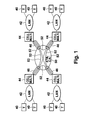
- Fig. 1 shows a digital transmission system in which the cell exchanging apparatus of the present invention may be used.
- the digital transmission system of Fig. 1 includes an ATM communication network 50.
- the system also includes terminals 40 that serve as the source and destination of cells that are passed across the network.
- the terminals are connected to local area networks (LAN) 42, which are, in turn, connected to cell multiplexing devices 44.
- LAN local area networks
- the cell multiplexing devices 44 serve as interfaces between LAN's 42 and the ATM communication network 50.
- Cells originating from a terminal pass through a LAN 42 to a cell mul - tiplexing device 44, wherein the cells are mul - tiplexed across the ATM communication network 50.
- Each of the cell multiplexing devices 44 is connected to a number of logical channels 46.
- the cell multiplexer decides which channel the cells are transmitted across. In making this decision, the cell multiplexing device selects a particular channel 52 that leads to the destination terminal.
- the cells are demultiplexed by a cell multiplexer device 44 that is coupled to a LAN 42 leading to the destination terminal 40. The demultiplexed cells are then transmitted over the LAN 42 to the destination terminal 40.
- the ATM communication network 50 must in - clude a number of switches to properly route cells across the network.
- the ATM network 50 is designed to operate at very high speeds (e.g. line bit-rates of 155 Mbps). As such, the switching must be done efficiently to maintain a high throughput.
- the present invention provides a cell exchanging apparatus that perform switching with - out omitting cells or repeating cells.
- a first preferred embodiment of a cell exchanging apparatus is shown in Fig. 2.
- the ATM cell exchanging apparatus of Fig. 2 is provided with a cell switch 11 for receiving cells from a plurality of input lines 2a to 2n (where n is a positive integer) and for outputting the received cells to a plurality of output lines 3a to 3m (where m is a positive integer).
- the ATM cell switching apparatus also includes an ad - ditional cell switch 12 that serves as a "spare cell” switch.
- This cell switch 12 has the same structure as cell switch 11 but has separate output lines 4a to 4m.
- Selectors 5a to 5m are coupled to the output lines 3a - 3m and 4a - 4m of the respective switches 11 and 12.
- the selectors 5a - 5m select either the output lines 3a to 3m of cell switch 11 or the output lines 4a to 4m of cell switch 12.
- the selectors 5a to 5m output cells received from the selected lines through lines 6a to 6m.
- the selectors 5a-5m make their choice of lines based on the system change-over signal. This signal will be described in more detail below.
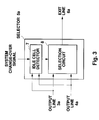
- Fig. 3 is a block diagram of the structure of selector 5a. Each of the other selectors 5b - 5m has an identical construction.
- the selector 5a includes an idle cell detector 7, for judging whether or not an idle or idle cell is output on the output lines 3a and 4a.
- a cell switch 11 or 12 (Fig. 1) has no cell to output to one of its output lines, a idle cell is output in place of a normal cell. Cells are typically 53 bytes in length, with 48 bytes of data and 5 bytes of header in - formation.
- a cell switch 11 or 12 When a cell switch 11 or 12 generates a idle cell it includes a 2 byte flag in the header information that identifies the cell as a idle cell.
- the idle cell detector 7 (Fig. 2) constantly monitors the output lines 3a and 4a of the two systems to determine whether any idle cells are output on lines 3a and 4a.
- the idle cell detector checks for the idle cell flag on incoming cells to determine whether the incoming cells are idle cells.
- the selector 5a further includes a selection circuit 8, for selecting either output line 3a or 4a and outputting the cell on the selected output line to the line 6a.
- Fig. 4 provides a more detailed view of one implementation of the selection circuit 8.
- the selection circuit includes two AND gates 54 and 56 and an inverter 60. If the system change - over signal is generated by an external system in response to a switch failure or other event, the idle cell detector 7 (Fig. 2) swaps the cell switch from which it selects cells by switching the selection circuit 8. Those skilled in the art will know of suitable mechanisms for generating such a system change-over signal. During normal operation, a swap signal sent from the idle cell detector 7 to the selection circuit 8 is high. As such, the cells output on line 3a (see Fig.
- the switching is performed only after detector 7 (Fig. 3) confirms that an idle cell is output to the output lines 3a and 4a of both systems.
- the sys - tems are not switched immediately after the sys - tem change - over signal is generated but is switched only after an idle cell is output from both cell switches 11, 12 to the respective output lines. It is, thus, possible to switch the systems by a very simple circuit structure which neither duplicates nor misses any cells; hence, enhancing the throughput of the network.
- cell switches 11 and 12 are shown for illustrative purposes as having four input lines 2a to 2d and four output lines 3a to 3d. It is assumed that each cell has a fixed length, and that cells reach the input lines 2a to 2d at substantially random times, pro - vided that the time interval between cells is equiv - alent to an integral multiple of the length of a cell. In other words, it is assumed that the input phases of the cells are normalized before they reach input lines 2a to 2d and that the cells are input from all the lines in the same phase.
- Fig. 5 is a timing chart for signals which are input on the input lines 2a to 2d and output to the output lines 3a to 3d.
- the numerals provided at the top of the chart represent time slot numbers. Only one cell is input to one input line for each time slot.
- the numeral at the left portion of each cell represents an output line number
- the numeral at the middle portion of each cell represents an input line number
- the number at the right portion of each cell represents a time slot number.
- the output line numbers 1 to 4 correspond to the output lines 3a to 3d, respectively
- the input line numbers 1 to 4 correspond to the input lines 2a to 3d, respectively.
- the time slot numbers each represent the number of the time slot in which the cell was input.
- the time slots showing no cells are the time slots in which no cell was received or in which a idle cell has been output.
- the cells which are input to the cell switch 11 are distributed to the specified output line numbers and output during the next time slot, as a general rule. If a plurality of cells which are to be delivered to the same output line are input during the same time slot, the cells are output one after another in a predetermined order.
- the order may be determined in various ways. In this illustrated case, a method is employed which outputs the cells according to their input line number in a circular order of 1 _ 2 - 3 - 4 . However, this method for ordering the output of the cells is merely illus - trative and other approaches may be equally viable.
- both of the cell switches 11 and 12 operate as described above, the order of outputting a plurality of cells which are to be delivered to the same address and which are input during the same time slot is sometimes different, depending upon the internal state of the cell switch. However, there is no time interval between the outputs of the cells. In other words, these plurality of cells are continu - ously output, and no idle cell is inserted between the cells.
- a plurality of cells when a plurality of cells are to be output to the same output line, they are output in a circular order, as described above.
- the order of outputting the cells is not critical to the present invention. In an extreme case, the cells may be output at random.
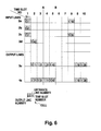
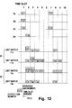
- Fig. 6 is a timing chart for signals which are input from the input lines 2a to 2d and output to the output line 3a of cell switch 11 and output line 4a of cell switch 12.
- the input cells are exchanged by the cell switches 11, 12 so that the cells are output to output lines 3a and 4a.
- the cell received on input line 2a is output to the output line 3a, whereas the cell received on input line 2b is output on the output line 4a during time slot 2.
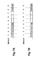
- the cell switches 11 and 12 exchange cells on the basis of the same control algorithm, but since the internal states of the cell switches 11 and 12 are not always the same, the order of outputting cells in cell switch 11 is sometimes different from the order in the cell switch 12, as shown in Fig. 6 (i.e., note the order in which the cells "111", “121” and “131” " are output on output lines 3a and 4a). In this case, if a changeover to system #2 occurs at time A in Fig. 6, a cell is duplicated or missed, as shown in Fig. 7A.
- the selector 5a (Fig. 3) which is connected to the output lines 3a and 4a receives a system change-over signal
- the selector 5a instructs the selection circuit 8 to switch after the idle cell detector 7 detects a idle cell which is output to the output lines of both systems at time B in Fig. 6. It is, thus, possible to switch systems without du - plicating or missing a cell.
- the selectors 5a to 5m (see Fig. 2) switch the systems in this way in - dependently of each other. Therefore, the operation of switching the systems in the entire ATM cell exchanging apparatus as a whole is completed when all the selectors 5a to 5m have finished the switching operation.
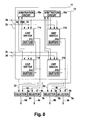
- FIG. 8 is a block diagram of another embodi - ment of an ATM cell exchanging apparatus according to the present invention.
- each of the cell switches 11 and 12 of this embodiment is composed of four unit switches 11 a - 11 d combined in the form of a lattice. These unit switches may be output buffer type switches, having buffers 61 a - 61 d for storing cells. Typically, each unit switch 11 a - 11 d is a 2x2 switch of a 4x4 switch.
- the cell switches 11 and 12 have arbitration circuits 10a and 10b for controlling the operation of outputting cells from unit switches 11 a to 11 to the respective output lines 3a to 3d and 4a to 4d.
- each of the cell switches 11 and 12 inputs cells from the four input lines 2a to 2d, distributes the cells to the corresponding addresses and outputs the cells through the plurality of output lines 3a to 3d or 4a to 4d.
- Each of the selectors 5a to 5d is composed of an idle detector 7 (Fig. 3) and a selection circuit 8 like those provided in the first embodiment.
- the selectors 5a to 5d (Fig. 8) select either the output lines 3a to 3d of the cell switch 11 or the output lines 4a to 4d of the cell switch 12, and output cells on the selected output lines through lines 6a to 6d.
- the selection circuit 8 (Fig. 3) is changed over to select the other switch after the idle cell detector 7 detects a idle cell which is output to the output lines of both switches.
- arbitration circuits 10a and 10b are provided for controlling the operation of the outputting cells from unit switches 11 a - 11 d to the respective output lines 3a - 3d and 4a-4d.
- the arbitration circuits are used when there is competition in requests for a particular output line.
- Fig. 9 provides a more detailed like diagram of the arbitration circuit 10a.
- the other arbitration circuit 10b has a like configuration.
- the arbitration circuit 10a includes a buffer 68, a microprocessor 62 and a memory 70. This arbitration circuit 10a receives requests from unit switch 11 d on line 64 and request from unit switch 11 on line 66. These requests are stored in a buffer 68 and are then forwarded to a microprocessor 62.
- the memory 70 holds a history of permission request to send information to a particular address.
- the microprocessor 62 uses the contents of memory 70 to determine whether permission should be granted for the request received on lines 64 and 66.
- the appropriate information is retrieved from the memory 70 by utilizing data contained in the request that are held in the buffer 68.
- the microprocessor then generates a permis - sion signal that is sent over line 72 or 74 back to the respective unit switch 11 or 11d, indicating that the request is permitted.
- the respective unit switch 11c or 11 then makes the appropriate switching connections to direct the cells to the appropriate output line 3c, 3d, 4c or 4d.
- Fig. 10 is a timing chart showing the timing for inputting cells to the input lines 2a to 2d.
- Figs. 11A-11H are timing diagrams showing the cells stored in the buffers of the unit switches 11 a to 11 d.
- Fig. 11A shows the cells stored in the buffer for the output line number 1 (output line 3a) of the unit switch 11 a (Fig. 8), and Fig. 11 B shows the cells stored in the buffer for the output line number 1 (output line 3a) of the unit switch 11 (Fig. 8).
- Fig. 11C shows the cells stored in the buffer for the output line number 2 (output line 3b) of the unit switch 11 a (Fig. 8), and
- Fig. 8D shows the cells stored in the buffer for the output line number 2 (output line 3b) of the unit switch 11 b (Fig. 8).
- Fig. 11 E shows the cells stored in the buffer for the output line number 3 (output line 3c) of the unit switch 11 c (Fig. 8), and Fig.
- FIG. 11 F shows the cells stored in the buffer for the output line number 3 (output line 3c) of the unit switch 11 d (Fig. 8).
- Fig. 11 G shows the cells stored in the buffer for the output line number 4 (output line 3d) of the unit switch 11 c (Fig. 8), and
- Fig. 11 H shows the cells stored in the buffer for the output line number 4 (output line 3d) of the unit switch 11 d (Fig. 8).
- Cells which are input at a certain time slot are distributed to the corresponding addresses within the unit switches 11 a - 11 d and stored in the corresponding buffers 61 a - 61 d at the next time slot. It will be understood for Figs. 10 and 11A-11H that each of the cells input, for example, at the time slot 1 is stored in the corresponding buffer at the time slot 2.
- Each of the unit switches 11 a to 11 d (Fig. 8) not only stores cells in its respective buffer 61a-61d but also requests permission from the corresponding arbitration circuit 10a or 10b to output a cell. If permission is granted, the unit 11a-11d switch outputs the cell at the next time slot. As shown in Fig. 12, cells having the output line number 1 are stored both in the unit switch 11 a and in the unit switch 11 b at time slots 2 and 3. In such a case, since it is impossible to output-both cells at the same time, the cells are output one by one, in accordance with the permission of the arbitration circuit 10b (10a).
- the arbitration circuit 10a or 10b instructs these buffers to alternately output a cell.
- a cell is output from the unit switch 11 a at the time slot 3
- a cell is output from the unit switch 11 b at the time slot 4
- a cell is output from the unit switch 11 a at the time slot 5. So long as some of the unit switches which are subject to request permission to output a cell, the arbitration circuit 10a or 10b grants permission to one of the unit switches.
- the arbitration circuit 10a (10b) instructs one of the unit switches 11 c and 11 d (11 a and 11 b) to output a idle cell.
- the arbitration circuit 10a or 10b grants permissions one by one to successive cells so long as there are requests for permission to output a cell.
- the order of outputting cells is not critical to this second embodiment. In an extreme case, there is no problem if the cells are output at random.
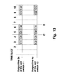
- Fig. 13 shows the cells output to the output line 3a of the cell switch 11 when the cells stored in the buffers are changed as shown in Fig. 12. Fig. 13 also shows the cells output to the output line 4a of the cell switch 12 in the same case.
- Fig. 14A shows the cells finally output to the exit line 6a in the case of changing the output line 3a over to the output line 4a at the time indicated by the line C in Fig. 13.
- Fig. 14B shows the cells finally output to line 6a in the case of changing the output line 3a over to the output line 4a at the time indicated by the line D in Fig. 13. Unlike the example shown in Fig. 14A, no cell is duplicated or missed.
- the selectors 5a to 5d in this second embodiment perform the switching operation only when an idle cell is output to the output lines of both systems in the same way as in the first embodiment, it is possible to switch the systems without causing a duplication or missing of a cell as in the first embodiment.
- the selectors 5a to 5d switch the systems independently of each other in the same way as the first embodiment. Therefore, the operation of switching the systems in the ATM cell exchanging apparatus as a whole is completed when all the selectors 5a to 5d have finished switching.
- the ATM cell switch is composed of the unit switches and the arbitration circuits, it is easy to realize an ATM cell switch which outputs an idle cell when there is no cell to be output. Therefore, the switching operation of the two sys - tems of an ATM cell exchanging apparatus is facilitated in the same way as in the first embodi - ment.
Applications Claiming Priority (4)
| Application Number | Priority Date | Filing Date | Title |
|---|---|---|---|
| JP30047691 | 1991-11-15 | ||
| JP300476/91 | 1991-11-15 | ||
| JP3618992A JP2671699B2 (ja) | 1991-11-15 | 1992-02-24 | セル交換装置 |
| JP36189/92 | 1992-02-24 |
Publications (2)
| Publication Number | Publication Date |
|---|---|
| EP0542233A2 true EP0542233A2 (fr) | 1993-05-19 |
| EP0542233A3 EP0542233A3 (en) | 1993-08-25 |
Family
ID=26375234
Family Applications (1)
| Application Number | Title | Priority Date | Filing Date |
|---|---|---|---|
| EP19920119295 Withdrawn EP0542233A3 (en) | 1991-11-15 | 1992-11-11 | Cell switching apparatus and method |
Country Status (4)
| Country | Link |
|---|---|
| US (1) | US5414696A (fr) |
| EP (1) | EP0542233A3 (fr) |
| JP (1) | JP2671699B2 (fr) |
| CA (1) | CA2082841C (fr) |
Cited By (3)
| Publication number | Priority date | Publication date | Assignee | Title |
|---|---|---|---|---|
| EP0645919A2 (fr) * | 1993-09-16 | 1995-03-29 | Siemens Aktiengesellschaft | Procédé pour la transmission de cellules de messages par les paires de voies redondantes virtuelles d'un réseau de communication ATM |
| EP0645918A2 (fr) * | 1993-09-16 | 1995-03-29 | Siemens Aktiengesellschaft | Procédé et dispositif de circuit pour la transmission de cellules de messages par les paires de voies redondantes virtuelles d'un réseau de communication ATM |
| GB2383509A (en) * | 2001-12-21 | 2003-06-25 | Agere Systems Inc | Switching between active and standby switch fabrics with no loss of data |
Families Citing this family (16)
| Publication number | Priority date | Publication date | Assignee | Title |
|---|---|---|---|---|
| JP2647003B2 (ja) * | 1994-05-24 | 1997-08-27 | 日本電気株式会社 | Atmスイッチの系切り替え制御方式 |
| KR100192651B1 (ko) * | 1994-12-07 | 1999-06-15 | 가나이 쓰도무 | 제어셀에 의해 입력셀의 전송을 제어하는 atm교환망, atm교환기 및 atm교환망에 있어서의 신호처리방법 |
| JP3574493B2 (ja) * | 1995-03-16 | 2004-10-06 | 富士通株式会社 | 回線切り替え制御方法および装置 |
| US5561791A (en) * | 1995-04-10 | 1996-10-01 | Digital Equipment Corporation | Method and apparatus for conditioning timed program independent of transport timing |
| DE19536518C2 (de) * | 1995-09-29 | 1998-07-09 | Siemens Ag | Verfahren zur Aufrechterhaltung des mikrosynchronen Betriebs von gedoppelten informationsverarbeitenden Einheiten |
| KR0150367B1 (ko) * | 1995-12-19 | 1998-11-02 | 양승택 | 완결 결합형 에이티엠 스위칭 장치 |
| JP2790112B2 (ja) * | 1996-02-16 | 1998-08-27 | 日本電気株式会社 | 遅延優先制御バッファの無瞬断切替装置及び切替方法 |
| JP3168908B2 (ja) * | 1996-04-11 | 2001-05-21 | 日本電気株式会社 | Atmセルのペイロード部情報の交換方法 |
| AU5595798A (en) * | 1996-12-12 | 1998-07-03 | Cascade Communications Corporation | Switch fabric switchover in an atm network switch |
| US6667954B1 (en) * | 2000-02-10 | 2003-12-23 | Tellabs Operations, Inc. | Methods and apparatus for selecting the better cell from redundant streams within a cell-oriented environment |
| JP3816314B2 (ja) * | 2000-07-11 | 2006-08-30 | 三菱電機株式会社 | パケット交換装置 |
| US6914878B1 (en) | 2000-10-16 | 2005-07-05 | Telefonaktiebolaget Lm Ericsson (Publ) | Fault detection in multi-plane switch |
| JP3736338B2 (ja) * | 2000-11-13 | 2006-01-18 | 株式会社日立製作所 | パケットスイッチ |
| US20030016654A1 (en) * | 2001-06-14 | 2003-01-23 | Jayanta Das | Network and access protection in optical networks |
| US8238341B2 (en) * | 2008-04-25 | 2012-08-07 | Chi Mei Communication Systems, Inc. | Apparatus and method for processing voice over internet protocol packets |
| JP6750353B2 (ja) * | 2016-07-07 | 2020-09-02 | 日本電気株式会社 | スイッチ回路およびこれを用いた半導体装置 |
Citations (8)
| Publication number | Priority date | Publication date | Assignee | Title |
|---|---|---|---|---|
| JPS62230138A (ja) * | 1986-03-31 | 1987-10-08 | Toshiba Corp | 二重化伝送路の切替装置 |
| EP0339735A1 (fr) * | 1988-04-29 | 1989-11-02 | AT&T NETWORK SYSTEMS INTERNATIONAL B.V. | Commutateur de jonction pour commutation de paquets |
| JPH01286645A (ja) * | 1988-05-13 | 1989-11-17 | Nippon Telegr & Teleph Corp <Ntt> | 伝送路切替方式 |
| JPH02200038A (ja) * | 1989-01-30 | 1990-08-08 | Nippon Telegr & Teleph Corp <Ntt> | 回線切換方式 |
| EP0410139A2 (fr) * | 1989-06-22 | 1991-01-30 | Fujitsu Limited | Système de commutation ATM avec structure à double commutateur |
| EP0455281A1 (fr) * | 1990-04-02 | 1991-11-06 | Koninklijke Philips Electronics N.V. | Module numérique de commutation de paquets pour l'allocation de paquets vides à des points de croisement |
| EP0455827A1 (fr) * | 1989-11-29 | 1991-11-13 | Fujitsu Limited | Procede de commutation pour systeme de commutateurs atm doubles |
| EP0503663A1 (fr) * | 1991-03-15 | 1992-09-16 | Fujitsu Limited | Dispositif et méthode pour la commutation continue à ATM |
Family Cites Families (24)
| Publication number | Priority date | Publication date | Assignee | Title |
|---|---|---|---|---|
| FR2538976A1 (fr) * | 1982-12-29 | 1984-07-06 | Servel Michel | Systeme de commutation de paquets synchrones de longueur fixe |
| KR900006793B1 (ko) * | 1984-10-18 | 1990-09-21 | 휴우즈 에어크라프트 캄파니 | 패킷 스위치 다중 대기행렬 NxM 스위치 노오드 및 처리 방법 |
| US4692894A (en) * | 1984-12-18 | 1987-09-08 | Advanced Micro Devices, Inc. | Overflow/Underflow detection for elastic buffer |
| US4734907A (en) * | 1985-09-06 | 1988-03-29 | Washington University | Broadcast packet switching network |
| US4920534A (en) * | 1986-02-28 | 1990-04-24 | At&T Bell Laboratories | System for controllably eliminating bits from packet information field based on indicator in header and amount of data in packet buffer |
| US4949301A (en) * | 1986-03-06 | 1990-08-14 | Advanced Micro Devices, Inc. | Improved pointer FIFO controller for converting a standard RAM into a simulated dual FIFO by controlling the RAM's address inputs |
| US4730305A (en) * | 1986-04-11 | 1988-03-08 | American Telephone And Telegraph Company, At&T Bell Laboratories | Fast assignment technique for use in a switching arrangement |
| US4821259A (en) * | 1986-09-05 | 1989-04-11 | American Telephone And Telegraph Company, At&T Bell Laboratories | Control information communication arrangement for a distributed control switching system |
| JPS63117241A (ja) * | 1986-11-05 | 1988-05-21 | Hitachi Ltd | 硬度測定方法およびその装置 |
| CA1297567C (fr) * | 1987-02-06 | 1992-03-17 | Kazuo Hajikano | Systeme de commutation a acheminement automatique |
| US4851991A (en) * | 1987-02-24 | 1989-07-25 | Digital Equipment Corporation | Central processor unit for digital data processing system including write buffer management mechanism |
| BE1000396A7 (fr) * | 1987-03-18 | 1988-11-22 | Electronique Et Telecomm Bell | Systeme de commutation. |
| US4910731A (en) * | 1987-07-15 | 1990-03-20 | Hitachi, Ltd. | Switching system and method of construction thereof |
| JPS63279443A (ja) * | 1987-05-11 | 1988-11-16 | Hitachi Ltd | 光ディスクの製造方法 |
| JPS63292962A (ja) * | 1987-05-26 | 1988-11-30 | Matsushita Electric Works Ltd | 消臭剤 |
| JPH0787456B2 (ja) * | 1987-05-28 | 1995-09-20 | 富士通株式会社 | 自己ル−チング交換機 |
| US5222085A (en) * | 1987-10-15 | 1993-06-22 | Peter Newman | Self-routing switching element and fast packet switch |
| SE462361B (sv) * | 1988-03-30 | 1990-06-11 | Ellemtel Utvecklings Ab | Paketdatavaeljare |
| DE68928867T2 (de) * | 1988-07-22 | 1999-04-29 | Hitachi Ltd | ATM-Vermittlungssystem |
| JPH0758963B2 (ja) * | 1989-01-27 | 1995-06-21 | 日本電気株式会社 | セル交換装置 |
| JP2910770B2 (ja) * | 1989-03-20 | 1999-06-23 | 富士通株式会社 | 自己ルーチング交換システム及び自己ルーチング交換システムの現用/予備切替え方法 |
| US5072440A (en) * | 1989-03-01 | 1991-12-10 | Fujitsu Limited | Self-routing switching system having dual self-routing switch module network structure |
| JP2795375B2 (ja) * | 1989-03-01 | 1998-09-10 | 富士通株式会社 | Atm交換装置及びその現用/予備切替え方法 |
| JPH03182140A (ja) * | 1989-12-11 | 1991-08-08 | Mitsubishi Electric Corp | 共通バッファ形交換装置 |
-
1992
- 1992-02-24 JP JP3618992A patent/JP2671699B2/ja not_active Expired - Fee Related
- 1992-11-11 EP EP19920119295 patent/EP0542233A3/en not_active Withdrawn
- 1992-11-12 US US07/975,104 patent/US5414696A/en not_active Expired - Fee Related
- 1992-11-13 CA CA 2082841 patent/CA2082841C/fr not_active Expired - Fee Related
Patent Citations (8)
| Publication number | Priority date | Publication date | Assignee | Title |
|---|---|---|---|---|
| JPS62230138A (ja) * | 1986-03-31 | 1987-10-08 | Toshiba Corp | 二重化伝送路の切替装置 |
| EP0339735A1 (fr) * | 1988-04-29 | 1989-11-02 | AT&T NETWORK SYSTEMS INTERNATIONAL B.V. | Commutateur de jonction pour commutation de paquets |
| JPH01286645A (ja) * | 1988-05-13 | 1989-11-17 | Nippon Telegr & Teleph Corp <Ntt> | 伝送路切替方式 |
| JPH02200038A (ja) * | 1989-01-30 | 1990-08-08 | Nippon Telegr & Teleph Corp <Ntt> | 回線切換方式 |
| EP0410139A2 (fr) * | 1989-06-22 | 1991-01-30 | Fujitsu Limited | Système de commutation ATM avec structure à double commutateur |
| EP0455827A1 (fr) * | 1989-11-29 | 1991-11-13 | Fujitsu Limited | Procede de commutation pour systeme de commutateurs atm doubles |
| EP0455281A1 (fr) * | 1990-04-02 | 1991-11-06 | Koninklijke Philips Electronics N.V. | Module numérique de commutation de paquets pour l'allocation de paquets vides à des points de croisement |
| EP0503663A1 (fr) * | 1991-03-15 | 1992-09-16 | Fujitsu Limited | Dispositif et méthode pour la commutation continue à ATM |
Non-Patent Citations (3)
| Title |
|---|
| PATENT ABSTRACTS OF JAPAN vol. 012, no. 099 (E-594)31 March 1988 & JP-A-62 230 138 (TOSHIBA) 8 October 1987 * |
| PATENT ABSTRACTS OF JAPAN vol. 014, no. 067 (E-0885)7 February 1990 & JP-A-01 286 645 (NTT) 17 November 1989 * |
| PATENT ABSTRACTS OF JAPAN vol. 014, no. 483 (E-0993)22 October 1990 & JP-A-02 200 038 (NTT) 8 August 1990 * |
Cited By (9)
| Publication number | Priority date | Publication date | Assignee | Title |
|---|---|---|---|---|
| EP0645919A2 (fr) * | 1993-09-16 | 1995-03-29 | Siemens Aktiengesellschaft | Procédé pour la transmission de cellules de messages par les paires de voies redondantes virtuelles d'un réseau de communication ATM |
| EP0645918A2 (fr) * | 1993-09-16 | 1995-03-29 | Siemens Aktiengesellschaft | Procédé et dispositif de circuit pour la transmission de cellules de messages par les paires de voies redondantes virtuelles d'un réseau de communication ATM |
| EP0645918A3 (fr) * | 1993-09-16 | 1995-12-20 | Siemens Ag | Procédé et dispositif de circuit pour la transmission de cellules de messages par les paires de voies redondantes virtuelles d'un réseau de communication ATM. |
| EP0645919A3 (fr) * | 1993-09-16 | 1995-12-27 | Siemens Ag | Procédé pour la transmission de cellules de messages par les paires de voies redondantes virtuelles d'un réseau de communication ATM. |
| US5559959A (en) * | 1993-09-16 | 1996-09-24 | Siemens Aktiengesellschaft | Method for transmitting message cells via redundant virtual path pairs of an atm communication network |
| US5671215A (en) * | 1993-09-16 | 1997-09-23 | Siemens Aktiengesellschaft | Method and circuit arrangement for transmitting message cells via redundant, virtual path pairs of an ATM communication network |
| GB2383509A (en) * | 2001-12-21 | 2003-06-25 | Agere Systems Inc | Switching between active and standby switch fabrics with no loss of data |
| GB2383509B (en) * | 2001-12-21 | 2005-03-09 | Agere Systems Inc | Method and apparatus for switching between active and standby switch fabrics with no loss of data |
| US7313089B2 (en) | 2001-12-21 | 2007-12-25 | Agere Systems Inc. | Method and apparatus for switching between active and standby switch fabrics with no loss of data |
Also Published As
| Publication number | Publication date |
|---|---|
| CA2082841A1 (fr) | 1993-05-16 |
| CA2082841C (fr) | 1999-02-23 |
| JP2671699B2 (ja) | 1997-10-29 |
| EP0542233A3 (en) | 1993-08-25 |
| JPH05191440A (ja) | 1993-07-30 |
| US5414696A (en) | 1995-05-09 |
Similar Documents
| Publication | Publication Date | Title |
|---|---|---|
| EP0542233A2 (fr) | Appareil et procédé pour la commutation de cellules | |
| AU693084B2 (en) | Controlled access ATM switch | |
| US5398235A (en) | Cell exchanging apparatus | |
| EP0300061B1 (fr) | Systeme de commutation a acheminement automatique | |
| US5790545A (en) | Efficient output-request packet switch and method | |
| CA2038121C (fr) | Central mta a fonction de duplication | |
| EP0195589B1 (fr) | Système de commutation pour la transmission de données | |
| US6915372B2 (en) | Methods and apparatus for managing traffic through a buffered crossbar switch fabric | |
| EP0256701B1 (fr) | Circuit d'interconnexion pour commutateurs de paquets de données à multiplexage spatial | |
| JPH10215260A (ja) | デジタル信号の双方向伝送のための経路指定スイッチ | |
| JPH10512422A (ja) | 大容量atm交換機 | |
| WO1997012494A1 (fr) | Architecture de commutation asymetrique pour noeud de commutation de reseau | |
| AU4057793A (en) | Output-buffered packet switch with a flexible buffer management scheme | |
| WO2001067691A1 (fr) | Commutateur de paquets crossbar nxn | |
| JPH10224377A (ja) | デジタル信号の双方向伝送のための経路指定スイッチ | |
| KR19980064825A (ko) | 에이.티.엠 스위치의 분산 버퍼링 시스템 | |
| JPH0338137A (ja) | 高速デイジタル・パケット交換システム | |
| JPH10190710A (ja) | アクセス調停方法 | |
| EP0415628A2 (fr) | Architecture extensible de commutateur de paquets | |
| US20100067536A1 (en) | Multimodal Data Switch | |
| JPH10107803A (ja) | トラヒックシェーピング装置 | |
| JPH10224376A (ja) | デジタル信号の双方向伝送用経路指定スイッチ | |
| KR100246627B1 (ko) | 트래픽 흐름제어 및 감시기능을 갖는 멀티채널 패킷 스위칭 장치 | |
| US7130301B2 (en) | Self-route expandable multi-memory packet switch with distributed scheduling means | |
| JPH10215262A (ja) | デジタル信号の双方向伝送のための経路指定スイッチ |
Legal Events
| Date | Code | Title | Description |
|---|---|---|---|
| PUAI | Public reference made under article 153(3) epc to a published international application that has entered the european phase |
Free format text: ORIGINAL CODE: 0009012 |
|
| AK | Designated contracting states |
Kind code of ref document: A2 Designated state(s): DE FR GB SE |
|
| PUAL | Search report despatched |
Free format text: ORIGINAL CODE: 0009013 |
|
| AK | Designated contracting states |
Kind code of ref document: A3 Designated state(s): DE FR GB SE |
|
| 17P | Request for examination filed |
Effective date: 19940128 |
|
| 17Q | First examination report despatched |
Effective date: 20021111 |
|
| GRAP | Despatch of communication of intention to grant a patent |
Free format text: ORIGINAL CODE: EPIDOSNIGR1 |
|
| STAA | Information on the status of an ep patent application or granted ep patent |
Free format text: STATUS: THE APPLICATION IS DEEMED TO BE WITHDRAWN |
|
| 18D | Application deemed to be withdrawn |
Effective date: 20040306 |