EP0645919A2 - Procédé pour la transmission de cellules de messages par les paires de voies redondantes virtuelles d'un réseau de communication ATM - Google Patents
Procédé pour la transmission de cellules de messages par les paires de voies redondantes virtuelles d'un réseau de communication ATM Download PDFInfo
- Publication number
- EP0645919A2 EP0645919A2 EP94114158A EP94114158A EP0645919A2 EP 0645919 A2 EP0645919 A2 EP 0645919A2 EP 94114158 A EP94114158 A EP 94114158A EP 94114158 A EP94114158 A EP 94114158A EP 0645919 A2 EP0645919 A2 EP 0645919A2
- Authority
- EP
- European Patent Office
- Prior art keywords
- message
- header
- cell
- coupling
- path
- Prior art date
- Legal status (The legal status is an assumption and is not a legal conclusion. Google has not performed a legal analysis and makes no representation as to the accuracy of the status listed.)
- Withdrawn
Links
Images

Classifications
-
- H—ELECTRICITY
- H04—ELECTRIC COMMUNICATION TECHNIQUE
- H04L—TRANSMISSION OF DIGITAL INFORMATION, e.g. TELEGRAPHIC COMMUNICATION
- H04L45/00—Routing or path finding of packets in data switching networks
- H04L45/02—Topology update or discovery
- H04L45/10—Routing in connection-oriented networks, e.g. X.25 or ATM
-
- H—ELECTRICITY
- H04—ELECTRIC COMMUNICATION TECHNIQUE
- H04L—TRANSMISSION OF DIGITAL INFORMATION, e.g. TELEGRAPHIC COMMUNICATION
- H04L45/00—Routing or path finding of packets in data switching networks
- H04L45/24—Multipath
-
- H—ELECTRICITY
- H04—ELECTRIC COMMUNICATION TECHNIQUE
- H04Q—SELECTING
- H04Q11/00—Selecting arrangements for multiplex systems
- H04Q11/04—Selecting arrangements for multiplex systems for time-division multiplexing
- H04Q11/0428—Integrated services digital network, i.e. systems for transmission of different types of digitised signals, e.g. speech, data, telecentral, television signals
- H04Q11/0478—Provisions for broadband connections
-
- H—ELECTRICITY
- H04—ELECTRIC COMMUNICATION TECHNIQUE
- H04L—TRANSMISSION OF DIGITAL INFORMATION, e.g. TELEGRAPHIC COMMUNICATION
- H04L12/00—Data switching networks
- H04L12/54—Store-and-forward switching systems
- H04L12/56—Packet switching systems
- H04L12/5601—Transfer mode dependent, e.g. ATM
- H04L2012/5619—Network Node Interface, e.g. tandem connections, transit switching
-
- H—ELECTRICITY
- H04—ELECTRIC COMMUNICATION TECHNIQUE
- H04L—TRANSMISSION OF DIGITAL INFORMATION, e.g. TELEGRAPHIC COMMUNICATION
- H04L12/00—Data switching networks
- H04L12/54—Store-and-forward switching systems
- H04L12/56—Packet switching systems
- H04L12/5601—Transfer mode dependent, e.g. ATM
- H04L2012/5625—Operations, administration and maintenance [OAM]
- H04L2012/5627—Fault tolerance and recovery
Definitions
- the invention relates to a method for transmitting message cells via redundant virtual path pairs of an ATM communication network according to the preamble of claim 1.
- ATM communication networks offer the possibility of combining a plurality of virtual connections into bundles, which are also referred to as virtual paths. Since such a virtual path can contain, for example, up to 65 536 virtual connections and can also have a high total bit rate of, for example, up to 2.4 Gbit / s, the virtual path in question is expediently a redundant virtual path pair with two separate virtual paths that run over different paths Paths designed to in the event of an error, i. H. to maintain the flow of information if one of the paths belonging to a pair of paths fails.
- the advantage of the invention is that in the case of multistage coupling devices with little control effort, the individual message cells only in that coupling stage of the respective coupling device be duplicated for a transmission via a path pair in which the two different transmission paths actually branch. The additional load on the respective coupling device by the duplicated message cells thus remains minimal.
- another expedient embodiment of the present invention is that the method according to the invention is carried out in all coupling devices located within the respective pair of paths. In this way, the control devices involved in the transmission of message cells can be designed in the same way in all coupling devices.
- FIG. 1 shows a detail of an ATM communication network ATMN which operates according to an asynchronous transfer mode ("Asynchronous Transfer Mode") and which consists of a.
- a large number of coupling devices are formed and, for example, as a feeder network for larger ATM switching devices may serve.
- virtual connections which run in the same direction and are set up in a known manner are carried out via so-called virtual paths, ie these virtual paths each carry a plurality of virtual connections.
- the coupling devices may be designed, for example, as so-called “cross connections", via which virtual paths are permanently established and remain in place for a long time.
- Such a virtual path can contain, for example, up to 65 536 virtual connections and can also have a high total bit rate of, for example, up to 2.4 Gbit / s, such a path must be switched to an alternative route as quickly as possible in the event of an error in order to minimize the loss of message cells transmitted within the individual virtual connections.
- an alternative path is defined within the ATM communication network for each path, hereinafter referred to as the active path.
- the respective active path and the associated replacement path are referred to below as the path pair.
- the active path and the associated replacement path run over separate paths in order to achieve a high level of reliability, for example, if possible, the same fiber bundles are not used within the ATM communication network for these two paths.
- a virtual path pair set up between two coupling devices is schematically represented as representative of a multiplicity of virtual path pairs running within the ATM communication network.
- the coupling devices are designated CCa and CCb.
- the coupling device CCa represents the beginning of the virtual path pair and receives the message cells occurring within a feeder path VPC at an interface device R1.
- the active one Path AP runs from the coupling device CCa via an interface device T2 connected to it and two intermediate coupling devices designated CC to an interface device designated R2 by the coupling device CCb.
- the associated replacement path EP is set up via an interface device T1 belonging to the coupling device CCa and an intermediate coupling device CC to an interface device R3 of the coupling device CCb.
- the message cells supplied to the coupling device CCa via the interface device R1 are duplicated and the message cells assigned to one another are transmitted separately to the coupling device CCb via the active path and the replacement path.
- the message cells transmitted via the replacement path are normally discarded and only the message cells transmitted via the active path are forwarded to an interface device T3 which represents an output of the coupling device CCb. Switching to the associated substitute path only occurs when faults occur on the active path, ie the message cells arriving via this substitute path are now forwarded to the interface device T3, while the message cells possibly still arriving via the active path are suppressed.
- each message cell is entered when it enters the respective coupling device is preceded by an internal cell header in addition to the existing external cell header and in accordance with this cell header.
- This has a number of head parts corresponding to the number of coupling stages of the respective coupling device, by means of which the path through the respective coupling stage, ie for example the output of the coupling stage, is determined.
- the order of the head parts corresponds to the order in which the coupling stages of the respective coupling device, here the coupling device CCa, are to be run through.
- each of the message cells is preceded by two internal cell headers, namely one for the active path and the remaining cell header for the replacement path.
- Each header is accompanied by a validity bit, which is initially set to a fixed logic level, for example to logic level "1".
- the header parts of the two internal cell heads assigned to it are compared with one another in each coupling stage. If these headers are identical, the message cell in question is forwarded to the subsequent coupling stage in accordance with the route information contained in the identical header parts, ie in accordance with the name of the output to be used. The validity bits of the header parts that have just been compared are deleted. If the headers compared with one another are not identical, on the other hand, the current message cell is duplicated. The resulting two message cells are then forwarded according to one of the two headers via different paths within the respective coupling stage.
- the validity bits are deleted in the header that has just been taken into account for forwarding and in the header of the other internal cell header. Finally, in the event that one of the headers compared to one another is marked as invalid (validity bit is deleted), the relevant message cell is only forwarded in accordance with the route information contained in the valid header.
- FIG. 2 shows as an example the case in which a message cell is preceded by two internal cell heads a and b, each of these internal cell heads having 5 headers in order to forward the message cell within a five-stage coupling device.
- the number given in the respective header indicates the output to be used for the respective switching stage.
- a validity bit is attached to each header, which is initially set to logic level "1".
- the route information contained in the first two header parts of the internal cell heads is identical (5, 20).
- the relevant message cell is thus transmitted to the third coupling stage via the output 5 of the first coupling stage and the output 20 of the second coupling stage.
- the validity bits of these headers are deleted.
- the headers assigned to the third coupling stage differ from one another, so that the message cell is duplicated in this third coupling stage.
- the resulting two message cells are then forwarded via outputs 1 and 17 of the third coupling stage.
- the message cell forwarded via path a (active path) is used in the header part of the internal cell header a assigned to the third coupling stage and in all header parts of the internal one Cell header b deleted the validity bit.
- the validity bit is deleted in the message cell transmitted via route b (alternative route) in the header part assigned to the third coupling stage and in all header parts of the internal cell header a.
- each incoming message cell is preceded by two identical internal cell heads.
- the message cells are then forwarded within the respective coupling device in accordance with the identical header parts contained in the internal cell heads.
- the above-described duplication of message cells in a coupling stage is particularly easy to implement if a central memory ("shared memory") and output queues assigned to it are provided within the individual coupling elements of this coupling stage.
- the respective message cell is only stored once in the central memory and read out twice, in each case when this message cell is next in line in the respective output queue for a transmission.
- the intermediate coupling device CC following this interruption inserts a signaling cell into the message cell stream, which is transmitted to the coupling device CCb and recognized there.
- a signaling cell For example, an alarm cell "VP-AIS" can be used as the signaling cell, as defined in accordance with CCITT recommendation I.610.
- the coupling device CCb detects the active cell Path-lying interface device R2 is blocked and, with the aid of a control signal transmitted to the interface device R3, the replacement path is switched through this interface device.
- the active path and the substitute path of the path pair shown in FIG. 1 are actively guided up to the interface device T3 of the coupling device CCb, i. H. the message cells to be transmitted via the replacement path are only discarded at this point in the normal case.
- the number of message cells arriving via the active path and the replacement path is continuously recorded separately at this interface device. Because of the runtime differences and the runtime fluctuations that are inevitable in the asynchronous transfer mode, there will generally be a difference in the recorded values, which, however, does not normally assume arbitrarily high values. However, if a fault occurs on the active path, for example in the form of an interruption, the number of message cells determined for the replacement path increases considerably compared to the number of message cells determined for the active path.
- the switchover takes place much faster than the switchover mentioned above with the aid of the interface devices R2 and R3.
- the interface device T3 counting means can be formed from a counter assigned to the active path and a counter assigned to the replacement path, the current counter readings of which are supplied to a device for forming the difference between the current counter readings.
- the message cells transmitted via the active path or substitute path are then switched through in accordance with the output signals emitted by this device, which are dependent on the respective difference.
- the counting means can also be formed from an up / down counter, the current counter reading of which can be changed in the other direction with the occurrence of a message cell transmitted via the active path, in the other direction with the occurrence of a message cell transmitted via the replacement path. In this case, the message cells arriving via the active path or replacement path are forwarded in accordance with the current counter reading of this up / down counter.
- the coupling device CCa inserts synchronization cells into the message cell streams transmitted via the active path and the replacement path at predetermined time intervals. With the occurrence of these synchronization cells in the coupling device CCb, the current counter reading is then of the above-mentioned counting means is set to a defined initial value.
- the runtime difference for the message cells to be transmitted within the ATM communication network is essentially given by the differences in the geometric path lengths.
- a path length of 1000 km is certainly a maximum value here, apart from satellite connections. 1000 km correspond to a running time of 4 ms. Values of approximately 300 ⁇ s are currently proposed for the maximum transit time variation when passing through a coupling device.
- the replacement path could now run over 10 coupling devices and a path length of 1000 km, while the active path runs over a single coupling device, is not heavily loaded and causes almost no delay.
- the maximum runtime difference is 7 ms, which corresponds to approximately 2500 cell cycles.
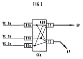
- the redundant path pair (active path AP and substitute path EP) is formed from three virtual connections VC1a, VC1b and VC1c. Message cells occurring in the course of these virtual connections are fed to the coupling device CCa via interface devices R1a, R1b and R1c. These message cells are duplicated in the coupling device CCa according to the principle described above.
- switching devices can also be provided in the ATM communication network as coupling devices instead of "cross connects", via which the virtual connections belonging to a virtual path pair are only set up in the course of establishing a connection.
- the present invention can not only be used, as described above, for the transmission of message cells via an active path and an alternative path assigned to it become. Rather, it is generally applicable when message cells are to be forwarded via different paths within an ATM communication network.
Applications Claiming Priority (2)
| Application Number | Priority Date | Filing Date | Title |
|---|---|---|---|
| DE4331579 | 1993-09-16 | ||
| DE4331579A DE4331579C2 (de) | 1993-09-16 | 1993-09-16 | Verfahren zum Übertragen von Nachrichtenzellen über redundante virtuelle Pfadpaare eines ATM-Kommunikationsnetzes |
Publications (2)
| Publication Number | Publication Date |
|---|---|
| EP0645919A2 true EP0645919A2 (fr) | 1995-03-29 |
| EP0645919A3 EP0645919A3 (fr) | 1995-12-27 |
Family
ID=6497913
Family Applications (1)
| Application Number | Title | Priority Date | Filing Date |
|---|---|---|---|
| EP94114158A Withdrawn EP0645919A3 (fr) | 1993-09-16 | 1994-09-08 | Procédé pour la transmission de cellules de messages par les paires de voies redondantes virtuelles d'un réseau de communication ATM. |
Country Status (5)
| Country | Link |
|---|---|
| US (1) | US5559959A (fr) |
| EP (1) | EP0645919A3 (fr) |
| JP (1) | JPH07170277A (fr) |
| CA (1) | CA2132068A1 (fr) |
| DE (1) | DE4331579C2 (fr) |
Cited By (11)
| Publication number | Priority date | Publication date | Assignee | Title |
|---|---|---|---|---|
| EP0683583A2 (fr) * | 1994-05-11 | 1995-11-22 | Siemens Aktiengesellschaft | Procédé et circuit pour réacheminer sans erreurs le flux de cellules d'information à travers une voie alternative |
| WO2003021896A1 (fr) * | 2001-08-31 | 2003-03-13 | Motorola, Inc. | Reseau actif de vehicule comportant des appareils tolerants aux fautes |
| WO2003021892A1 (fr) * | 2001-08-31 | 2003-03-13 | Motorola Inc. | Reseau actif pour vehicules a portion reservee |
| WO2003021867A2 (fr) * | 2001-08-31 | 2003-03-13 | Motorola, Inc. | Reseaux actifs de vehicules relies |
| WO2003021897A1 (fr) * | 2001-08-31 | 2003-03-13 | Motorola, Inc. | Reseau actif de vehicule a structure centrale |
| WO2003021894A1 (fr) * | 2001-08-31 | 2003-03-13 | Motorola, Inc. | Reseau actif de vehicule avec redondance de chemin de communication |
| WO2003021895A1 (fr) * | 2001-08-31 | 2003-03-13 | Motorola, Inc. A Corporation Of The State Of Delaware | Reseau actif de vehicule adapte a une architecture specifique |
| WO2003021893A1 (fr) * | 2001-08-31 | 2003-03-13 | Motorola, Inc. | Reseau actif pour vehicules a redondance de donnees |
| WO2003021898A1 (fr) * | 2001-08-31 | 2003-03-13 | Motorola, Inc. | Reseau actif pour vehicules a dispositifs redondants |
| EP1526690A2 (fr) * | 2003-10-16 | 2005-04-27 | Alcatel | Système et procédé pour fournir des communications dans un réseau en utilisant une architecture redondante de commutation |
| US7610492B2 (en) | 2004-10-08 | 2009-10-27 | Fujitsu Limited | Biometric authentication device, biometric information authentication method, and program |
Families Citing this family (28)
| Publication number | Priority date | Publication date | Assignee | Title |
|---|---|---|---|---|
| DE19523986A1 (de) * | 1995-06-30 | 1997-01-02 | Siemens Ag | ATM-Kommunikationsnetz |
| FR2737371A1 (fr) * | 1995-07-26 | 1997-01-31 | Trt Telecom Radio Electr | Securisation par doublement d'au moins certaines voies logiques dans un reseau de telecommunications |
| ATE389995T1 (de) * | 1997-03-27 | 2008-04-15 | Nokia Siemens Networks Gmbh | Redundantes übertragungssystem mit abschaltung einer übertragungsstrecke fehlerhaften übertragungsverhaltens |
| EP0868103A3 (fr) * | 1997-03-27 | 2002-10-16 | Siemens Aktiengesellschaft | Acceptation des connexions avec priorité inférieure, en particulier du traffic en temps non reél (NRT), seulement par des voies redondantes |
| US6011780A (en) * | 1997-05-23 | 2000-01-04 | Stevens Institute Of Technology | Transparant non-disruptable ATM network |
| DE19726003A1 (de) * | 1997-06-19 | 1998-12-24 | Alsthom Cge Alcatel | Verfahren zum Übermitteln verschlüsselter Signale, sowie Sendeeinrichtung und Empfangseinrichtung dafür |
| WO2000013376A1 (fr) * | 1998-08-28 | 2000-03-09 | Integral Access, Inc. | Communication de donnees a redondance des chemins |
| US6510156B1 (en) | 1998-12-07 | 2003-01-21 | Cisco Technology, Inc. | Method and apparatus for data stream optimization |
| US7463581B1 (en) | 2000-02-07 | 2008-12-09 | Cisco Technology, Inc. | Re-routing connections using redundant path connections and loopbacks |
| US7747747B1 (en) * | 2002-05-06 | 2010-06-29 | Apple Inc. | Method and arrangement for supressing duplicate network resources |
| US7469282B2 (en) | 2003-01-21 | 2008-12-23 | At&T Intellectual Property I, L.P. | Method and system for provisioning and maintaining a circuit in a data network |
| WO2004102902A1 (fr) * | 2003-05-14 | 2004-11-25 | Fujitsu Limited | Procede et dispositif de commande de redondance de noeud |
| US7350099B2 (en) * | 2003-12-23 | 2008-03-25 | At&T Bls Intellectual Property, Inc. | Method and system for utilizing a logical failover circuit for rerouting data between data networks |
| US7639623B2 (en) * | 2003-12-23 | 2009-12-29 | At&T Intellectual Property I, L.P. | Method and system for real time simultaneous monitoring of logical circuits in a data network |
| US8199638B2 (en) | 2003-12-23 | 2012-06-12 | At&T Intellectual Property I, L.P. | Method and system for automatically rerouting logical circuit data in a data network |
| US7630302B2 (en) * | 2003-12-23 | 2009-12-08 | At&T Intellectual Property I, L.P. | Method and system for providing a failover circuit for rerouting logical circuit data in a data network |
| US8203933B2 (en) | 2003-12-23 | 2012-06-19 | At&T Intellectual Property I, L.P. | Method and system for automatically identifying a logical circuit failure in a data network |
| US7639606B2 (en) | 2003-12-23 | 2009-12-29 | At&T Intellectual Property I, L.P. | Method and system for automatically rerouting logical circuit data in a virtual private network |
| US7609623B2 (en) | 2003-12-23 | 2009-10-27 | At&T Intellectual Property I, L.P. | Method and system for automatically rerouting data from an overbalanced logical circuit in a data network |
| US7646707B2 (en) * | 2003-12-23 | 2010-01-12 | At&T Intellectual Property I, L.P. | Method and system for automatically renaming logical circuit identifiers for rerouted logical circuits in a data network |
| US8223632B2 (en) | 2003-12-23 | 2012-07-17 | At&T Intellectual Property I, L.P. | Method and system for prioritized rerouting of logical circuit data in a data network |
| US7460468B2 (en) | 2004-04-22 | 2008-12-02 | At&T Intellectual Property I, L.P. | Method and system for automatically tracking the rerouting of logical circuit data in a data network |
| US7466646B2 (en) | 2004-04-22 | 2008-12-16 | At&T Intellectual Property I, L.P. | Method and system for automatically rerouting logical circuit data from a logical circuit failure to dedicated backup circuit in a data network |
| US7275192B2 (en) * | 2004-04-22 | 2007-09-25 | At&T Bls Intellectual Property, Inc. | Method and system for on demand selective rerouting of logical circuit data in a data network |
| US8339988B2 (en) | 2004-04-22 | 2012-12-25 | At&T Intellectual Property I, L.P. | Method and system for provisioning logical circuits for intermittent use in a data network |
| US7768904B2 (en) | 2004-04-22 | 2010-08-03 | At&T Intellectual Property I, L.P. | Method and system for fail-safe renaming of logical circuit identifiers for rerouted logical circuits in a data network |
| GB0519648D0 (en) * | 2005-09-27 | 2005-11-02 | Roke Manor Research | Resilient path protocol |
| US8295162B2 (en) | 2006-05-16 | 2012-10-23 | At&T Intellectual Property I, L.P. | System and method to achieve sub-second routing performance |
Citations (4)
| Publication number | Priority date | Publication date | Assignee | Title |
|---|---|---|---|---|
| EP0505601A1 (fr) * | 1991-03-28 | 1992-09-30 | Siemens Aktiengesellschaft | Procédé pour transmettre des paquets d'information redondants via des dispositifs de commutation redondants |
| EP0542233A2 (fr) * | 1991-11-15 | 1993-05-19 | Mitsubishi Denki Kabushiki Kaisha | Appareil et procédé pour la commutation de cellules |
| DE4317951C1 (de) * | 1993-05-28 | 1994-05-26 | Siemens Ag | Verfahren und Schaltungsanordnung zur Übertragung von Nachrichtenpaketen nach dem Asynchronen Transfermodus in einem Kommunikationsnetz |
| EP0384936B1 (fr) * | 1989-03-03 | 1994-06-15 | Siemens Aktiengesellschaft | Procédé et dispositif pour transmettre des paquets d'information provenant de lignes d'entrée via un dispositif à communication de paquets |
Family Cites Families (17)
| Publication number | Priority date | Publication date | Assignee | Title |
|---|---|---|---|---|
| DE3513165A1 (de) * | 1985-04-12 | 1986-10-16 | Siemens AG, 1000 Berlin und 8000 München | Schaltungsanordnung fuer fernmeldevermittlungsanlagen, insbesondere fernsprechvermittlungsanlagen, mit einrichtungen zur funktionsfaehigkeitspruefung durchgeschalteter verbindungen |
| GB8802533D0 (en) * | 1988-02-04 | 1988-03-02 | Plessey Co Plc | Data packet switching |
| US5185736A (en) * | 1989-05-12 | 1993-02-09 | Alcatel Na Network Systems Corp. | Synchronous optical transmission system |
| JPH03104451A (ja) * | 1989-09-19 | 1991-05-01 | Fujitsu Ltd | 多段リンク交換システムのルート切替え方式 |
| GB2236930B (en) * | 1989-10-11 | 1994-03-23 | Plessey Co Plc | Method and apparatus for identifying valid cells in a redundant path combining unit of an asynchronous transfer mode switch |
| DE59007070D1 (de) * | 1990-04-27 | 1994-10-13 | Siemens Ag | Verfahren und Schaltungsanordnung zur Reduzierung des Verlustes von Nachrichtenpaketen, die über eine Paketvermittlungseinrichtung übertragen werden. |
| EP0470341B1 (fr) * | 1990-08-10 | 1995-09-20 | Siemens Aktiengesellschaft | Méthode et agencement de commutation pour la réception et la transmission de cellules d'information transmises selon le mode de transfert asynchrone dans un dispositif de commutation ATM |
| JPH04229747A (ja) * | 1990-08-17 | 1992-08-19 | Hitachi Ltd | パケット交換方法、およびパケット交換システム |
| GB9019340D0 (en) * | 1990-09-05 | 1990-10-17 | Plessey Telecomm | An asynchronous transfer mode switching arrangement providing broadcast transmission |
| JPH04154242A (ja) * | 1990-10-17 | 1992-05-27 | Nec Corp | ネットワーク障害回復方式 |
| DE69116673T2 (de) * | 1991-02-13 | 1996-08-08 | Bell Telephone Mfg | Bandbreitezuteilung für permanente virtuelle Verbindungen |
| US5278977A (en) * | 1991-03-19 | 1994-01-11 | Bull Hn Information Systems Inc. | Intelligent node resident failure test and response in a multi-node system |
| JP2578704B2 (ja) * | 1991-03-26 | 1997-02-05 | 日本電信電話株式会社 | リング伝送網のループバック方法およびリング伝送装置 |
| EP0512141A1 (fr) * | 1991-05-07 | 1992-11-11 | Siemens Aktiengesellschaft | Procédé pour commuter un flux de données du type ATM à grand débit dans un réseau de commutation à débit faible |
| US5398235A (en) * | 1991-11-15 | 1995-03-14 | Mitsubishi Denki Kabushiki Kaisha | Cell exchanging apparatus |
| ATE162034T1 (de) * | 1992-08-28 | 1998-01-15 | Siemens Ag | Verfahren und schaltungsanordnung zum übertragen von nachrichtenzellen innerhalb eines atm-netzes |
| US5402415A (en) * | 1993-04-22 | 1995-03-28 | Washington University | Multicast virtual circuit switch using cell recycling |
-
1993
- 1993-09-16 DE DE4331579A patent/DE4331579C2/de not_active Expired - Fee Related
-
1994
- 1994-09-08 EP EP94114158A patent/EP0645919A3/fr not_active Withdrawn
- 1994-09-09 US US08/303,941 patent/US5559959A/en not_active Expired - Fee Related
- 1994-09-12 JP JP6217547A patent/JPH07170277A/ja not_active Withdrawn
- 1994-09-14 CA CA002132068A patent/CA2132068A1/fr not_active Abandoned
Patent Citations (4)
| Publication number | Priority date | Publication date | Assignee | Title |
|---|---|---|---|---|
| EP0384936B1 (fr) * | 1989-03-03 | 1994-06-15 | Siemens Aktiengesellschaft | Procédé et dispositif pour transmettre des paquets d'information provenant de lignes d'entrée via un dispositif à communication de paquets |
| EP0505601A1 (fr) * | 1991-03-28 | 1992-09-30 | Siemens Aktiengesellschaft | Procédé pour transmettre des paquets d'information redondants via des dispositifs de commutation redondants |
| EP0542233A2 (fr) * | 1991-11-15 | 1993-05-19 | Mitsubishi Denki Kabushiki Kaisha | Appareil et procédé pour la commutation de cellules |
| DE4317951C1 (de) * | 1993-05-28 | 1994-05-26 | Siemens Ag | Verfahren und Schaltungsanordnung zur Übertragung von Nachrichtenpaketen nach dem Asynchronen Transfermodus in einem Kommunikationsnetz |
Cited By (16)
| Publication number | Priority date | Publication date | Assignee | Title |
|---|---|---|---|---|
| EP0683583A2 (fr) * | 1994-05-11 | 1995-11-22 | Siemens Aktiengesellschaft | Procédé et circuit pour réacheminer sans erreurs le flux de cellules d'information à travers une voie alternative |
| EP0683583A3 (fr) * | 1994-05-11 | 1996-07-17 | Siemens Ag | Procédé et circuit pour réacheminer sans erreurs le flux de cellules d'information à travers une voie alternative. |
| WO2003021893A1 (fr) * | 2001-08-31 | 2003-03-13 | Motorola, Inc. | Reseau actif pour vehicules a redondance de donnees |
| WO2003021898A1 (fr) * | 2001-08-31 | 2003-03-13 | Motorola, Inc. | Reseau actif pour vehicules a dispositifs redondants |
| WO2003021867A2 (fr) * | 2001-08-31 | 2003-03-13 | Motorola, Inc. | Reseaux actifs de vehicules relies |
| WO2003021897A1 (fr) * | 2001-08-31 | 2003-03-13 | Motorola, Inc. | Reseau actif de vehicule a structure centrale |
| WO2003021894A1 (fr) * | 2001-08-31 | 2003-03-13 | Motorola, Inc. | Reseau actif de vehicule avec redondance de chemin de communication |
| WO2003021895A1 (fr) * | 2001-08-31 | 2003-03-13 | Motorola, Inc. A Corporation Of The State Of Delaware | Reseau actif de vehicule adapte a une architecture specifique |
| WO2003021896A1 (fr) * | 2001-08-31 | 2003-03-13 | Motorola, Inc. | Reseau actif de vehicule comportant des appareils tolerants aux fautes |
| WO2003021892A1 (fr) * | 2001-08-31 | 2003-03-13 | Motorola Inc. | Reseau actif pour vehicules a portion reservee |
| WO2003021867A3 (fr) * | 2001-08-31 | 2003-10-09 | Motorola Inc | Reseaux actifs de vehicules relies |
| US8194536B2 (en) * | 2001-08-31 | 2012-06-05 | Continental Automotive Systems, Inc. | Vehicle active network with fault tolerant devices |
| EP1526690A3 (fr) * | 2003-10-16 | 2007-05-23 | Alcatel Lucent | Système et procédé pour fournir des communications dans un réseau en utilisant une architecture redondante de commutation |
| US7376133B2 (en) | 2003-10-16 | 2008-05-20 | Alcatel-Lucent | System and method for providing communications in a network using a redundant switching architecture |
| EP1526690A2 (fr) * | 2003-10-16 | 2005-04-27 | Alcatel | Système et procédé pour fournir des communications dans un réseau en utilisant une architecture redondante de commutation |
| US7610492B2 (en) | 2004-10-08 | 2009-10-27 | Fujitsu Limited | Biometric authentication device, biometric information authentication method, and program |
Also Published As
| Publication number | Publication date |
|---|---|
| DE4331579A1 (de) | 1995-03-30 |
| DE4331579C2 (de) | 1995-07-06 |
| CA2132068A1 (fr) | 1995-03-17 |
| US5559959A (en) | 1996-09-24 |
| EP0645919A3 (fr) | 1995-12-27 |
| JPH07170277A (ja) | 1995-07-04 |
Similar Documents
| Publication | Publication Date | Title |
|---|---|---|
| EP0645919A2 (fr) | Procédé pour la transmission de cellules de messages par les paires de voies redondantes virtuelles d'un réseau de communication ATM | |
| EP0645918A2 (fr) | Procédé et dispositif de circuit pour la transmission de cellules de messages par les paires de voies redondantes virtuelles d'un réseau de communication ATM | |
| EP0384936B1 (fr) | Procédé et dispositif pour transmettre des paquets d'information provenant de lignes d'entrée via un dispositif à communication de paquets | |
| EP0453607B1 (fr) | Méthode et dispositif pour réduire la perte de paquets d'information, transmis par un commutateur de paquets | |
| EP0419958B1 (fr) | Circuit dans un central de commutation à multiplexage temporel asynchrone pour détecter la quantité de données transmises et pour contrÔler la conformité avec des taux de bits specifiés | |
| EP0566961B1 (fr) | Procédé et circuit pour faire respecter le débit de transmission préaccordé dans un dispositif de commutation ATM | |
| EP0645913A2 (fr) | Procédé et dispositif pour transmettre des cellules ATM sur des chemins virtuels | |
| EP0419959B1 (fr) | Circuit pour contrÔler le respet de débits préétablis lors de la transmission de cellules de données | |
| EP0342547A1 (fr) | Procédé pour la génération d'un signal pour supprimer un alarme | |
| EP0453606B1 (fr) | Méthode et dispositif pour réduire la perte de paquets d'information, transmis par un commutateur de paquets | |
| DE4434724C1 (de) | Verfahren und Schaltungsanordnung zum Weiterleiten von einer ATM-Kommunikationseinrichtung zugeführten Nachrichtenzellen | |
| EP0682422A2 (fr) | Méthode et dispositif pour synchroniser un train de cellules transmis avec redondance | |
| EP0751693A2 (fr) | Réseau de communication ATM | |
| EP0513511B1 (fr) | Procédé pour le contrÔle de l'admissibilité d'établissement des connexions virtuelles | |
| EP0572831B1 (fr) | Méthode pour surveiller la participation et réduire les erreurs de bit pour communications commutées dans un système numérique | |
| EP0582848A2 (fr) | Procédé de détection d'erreurs dans des systèmes de communication numériques | |
| EP0673136A1 (fr) | Méthode et dispositif de commande de transmission de blocs de données dans un système de communication | |
| DE4446248C2 (de) | Übertragungssystem | |
| EP0173274B1 (fr) | Méthode et montage pour la réalisation et la maintenance d'une liaison à division temporelle à large bande | |
| EP0720411B1 (fr) | Méthode et système pour la surveillance d'un courant de cellules ATM | |
| EP0732828A2 (fr) | Réseau de communication optimisé en redondance pour la transmission de signaux de données | |
| EP0584387B1 (fr) | Procédé et circuit pour surveiller l'agencement de cellules pendant la transmission des cellules d'information | |
| EP0762696A1 (fr) | Réseau local à Mode de Transfert Asynchrone pour la génération de cellules à priorité | |
| DE19703993A1 (de) | Schaltungsanordnung zum Ersatzschalten von Übertragungseinrichtungen in Ringarchitekturen zur bidirektionalen Übertragung von ATM-Zellen | |
| DE69929151T2 (de) | Verfahren zur Überwachung des Paketverlustes in einem Kommunikationssystem |
Legal Events
| Date | Code | Title | Description |
|---|---|---|---|
| PUAI | Public reference made under article 153(3) epc to a published international application that has entered the european phase |
Free format text: ORIGINAL CODE: 0009012 |
|
| AK | Designated contracting states |
Kind code of ref document: A2 Designated state(s): AT BE CH FR GB IT LI NL SE |
|
| PUAL | Search report despatched |
Free format text: ORIGINAL CODE: 0009013 |
|
| RHK1 | Main classification (correction) |
Ipc: H04L 12/56 |
|
| AK | Designated contracting states |
Kind code of ref document: A3 Designated state(s): AT BE CH FR GB IT LI NL SE |
|
| 17P | Request for examination filed |
Effective date: 19960119 |
|
| 17Q | First examination report despatched |
Effective date: 20000714 |
|
| STAA | Information on the status of an ep patent application or granted ep patent |
Free format text: STATUS: THE APPLICATION IS DEEMED TO BE WITHDRAWN |
|
| 18D | Application deemed to be withdrawn |
Effective date: 20001125 |