EP0645918A2 - Procédé et dispositif de circuit pour la transmission de cellules de messages par les paires de voies redondantes virtuelles d'un réseau de communication ATM - Google Patents
Procédé et dispositif de circuit pour la transmission de cellules de messages par les paires de voies redondantes virtuelles d'un réseau de communication ATM Download PDFInfo
- Publication number
- EP0645918A2 EP0645918A2 EP94114157A EP94114157A EP0645918A2 EP 0645918 A2 EP0645918 A2 EP 0645918A2 EP 94114157 A EP94114157 A EP 94114157A EP 94114157 A EP94114157 A EP 94114157A EP 0645918 A2 EP0645918 A2 EP 0645918A2
- Authority
- EP
- European Patent Office
- Prior art keywords
- path
- message cells
- message
- coupling device
- active
- Prior art date
- Legal status (The legal status is an assumption and is not a legal conclusion. Google has not performed a legal analysis and makes no representation as to the accuracy of the status listed.)
- Withdrawn
Links
Images

Classifications
-
- H—ELECTRICITY
- H04—ELECTRIC COMMUNICATION TECHNIQUE
- H04Q—SELECTING
- H04Q11/00—Selecting arrangements for multiplex systems
- H04Q11/04—Selecting arrangements for multiplex systems for time-division multiplexing
- H04Q11/0428—Integrated services digital network, i.e. systems for transmission of different types of digitised signals, e.g. speech, data, telecentral, television signals
- H04Q11/0478—Provisions for broadband connections
-
- H—ELECTRICITY
- H04—ELECTRIC COMMUNICATION TECHNIQUE
- H04L—TRANSMISSION OF DIGITAL INFORMATION, e.g. TELEGRAPHIC COMMUNICATION
- H04L1/00—Arrangements for detecting or preventing errors in the information received
- H04L1/22—Arrangements for detecting or preventing errors in the information received using redundant apparatus to increase reliability
-
- H—ELECTRICITY
- H04—ELECTRIC COMMUNICATION TECHNIQUE
- H04L—TRANSMISSION OF DIGITAL INFORMATION, e.g. TELEGRAPHIC COMMUNICATION
- H04L69/00—Network arrangements, protocols or services independent of the application payload and not provided for in the other groups of this subclass
- H04L69/40—Network arrangements, protocols or services independent of the application payload and not provided for in the other groups of this subclass for recovering from a failure of a protocol instance or entity, e.g. service redundancy protocols, protocol state redundancy or protocol service redirection
-
- H—ELECTRICITY
- H04—ELECTRIC COMMUNICATION TECHNIQUE
- H04L—TRANSMISSION OF DIGITAL INFORMATION, e.g. TELEGRAPHIC COMMUNICATION
- H04L12/00—Data switching networks
- H04L12/54—Store-and-forward switching systems
- H04L12/56—Packet switching systems
- H04L12/5601—Transfer mode dependent, e.g. ATM
- H04L2012/5619—Network Node Interface, e.g. tandem connections, transit switching
-
- H—ELECTRICITY
- H04—ELECTRIC COMMUNICATION TECHNIQUE
- H04L—TRANSMISSION OF DIGITAL INFORMATION, e.g. TELEGRAPHIC COMMUNICATION
- H04L12/00—Data switching networks
- H04L12/54—Store-and-forward switching systems
- H04L12/56—Packet switching systems
- H04L12/5601—Transfer mode dependent, e.g. ATM
- H04L2012/5625—Operations, administration and maintenance [OAM]
- H04L2012/5627—Fault tolerance and recovery
Definitions
- the invention relates to a method for transmitting message cells via redundant virtual path pairs of an ATM communication network according to the preamble of claim 1 and of claim 3 and a circuit arrangement according to the preamble of claim 5 for carrying out the method according to claim 1.
- ATM communication networks offer the possibility of combining a plurality of virtual connections into bundles, which are also referred to as virtual paths. Since such a virtual path can contain, for example, up to 65 536 virtual connections and can also have a high total bit rate of, for example, up to 2.4 Gbit / s, in the event of an error the relevant virtual path must be able to be switched to an alternative route as quickly as possible in order to avoid the information loss to keep it low for the individual virtual connections.
- the advantage of the invention is that with low control effort in the event of failure of an active path can be switched to an associated substitute path.
- Another advantage of the method according to claim 1 is the separate detection of the number of message cells to be transmitted via the active path and the replacement path. In this way, even in the event of an increased loss of message cells on the active path, a switchover to the replacement path can be carried out without a complete failure.
- An advantageous embodiment of the method according to claim 1 results from claim 2.
- the advantage of this embodiment consists in the transmission of synchronization cells and their evaluation in the coupling device located at the end of the respective path pair by the number of those via an active path and an associated one To set the replacement path transmitted message cells to a uniform starting value at predetermined time intervals. In this way, it is also ensured that, in the event that message cells with different cell loss probabilities are transmitted via an active path and the associated substitute path, it is ensured that the difference between the number of message cells transmitted via an active path and the associated substitute path is below one for one Path switching specified threshold lies.
- a further embodiment of the method according to claims 1 and 3 emerges from claim 4.
- the advantage of this embodiment is that, in the case of coupling devices with multiple stages, the individual message cells are only duplicated in the coupling stage for transmission via a pair of paths in which the two different transmission paths branch. The additional burden the respective coupling device through the duplicated message cells thus remains minimal.
- the above-mentioned object is achieved in a circuit arrangement of the type mentioned by the circuitry features specified in claim 5.
- the advantage of this circuit arrangement is that it requires relatively little circuitry in order to be able to quickly switch between the active path and the associated replacement path in the case of a pair of paths.
- FIG. 1 shows a section of an ATM communication network ATMN, which operates according to an asynchronous transfer mode ("Asynchronous Transfer Mode") and which is formed from a large number of switching devices and may serve, for example, as a feeder network for larger ATM switching devices.
- ATM communication network virtual connections that run in the same direction and are set up in a known manner are conducted via so-called virtual paths, ie these virtual paths each carry a plurality of virtual connections.
- the coupling devices may be designed, for example, as so-called “cross connections", via which virtual paths are permanently established and remain in place for a long time.
- Such a virtual path can contain, for example, up to 65 536 virtual connections and can also have a high total bit rate of, for example, up to 2.4 Gbit / s, such a path must be switched to an alternative route as quickly as possible in the event of an error in order to minimize the loss of message cells transmitted within the individual virtual connections.
- an alternative path is defined within the ATM communication network for each path, hereinafter referred to as the active path.
- the respective active path and the associated replacement path are referred to below as the path pair.
- the active path and the associated replacement path run over separate paths in order to achieve a high degree of reliability. For example, if possible, the same fiber bundles are not used within the ATM communication network for these two paths.
- a virtual path pair set up between two coupling devices is schematically represented as representative of a multiplicity of virtual path pairs running within the ATM communication network.
- the coupling devices are designated CCa and CCb.
- the coupling device CCa represents the beginning of the virtual path pair and receives the message cells occurring within a feeder path VPC at an interface device R1.
- the active one Path AP runs from the coupling device CCa via an interface device T2 connected to it and two intermediate coupling devices designated CC to an interface device designated R2 by the coupling device CCb.
- the associated replacement path EP is set up via an interface device T1 belonging to the coupling device CCa and an intermediate coupling device CC to an interface device R3 of the coupling device CCb.
- the message cells supplied to the coupling device CCa via the interface device R1 are duplicated and the message cells assigned to one another are transmitted separately to the coupling device CCb via the active path and the replacement path.
- the message cells transmitted via the replacement path are normally discarded and only the message cells transmitted via the active path are forwarded to an interface device T3 which represents an output of the coupling device CCb. Switching to the associated substitute path only occurs when faults occur on the active path, ie the message cells arriving via this substitute path are now forwarded to the interface device T3, while the message cells possibly still arriving via the active path are suppressed.
- each message cell is entered when it enters the respective coupling device is preceded by an internal cell header in addition to the existing external cell header and in accordance with this cell header.
- This has a number of head parts corresponding to the number of coupling stages of the respective coupling device, by means of which the path through the respective coupling stage, ie for example the output of the coupling stage, is determined.
- the order of the head parts corresponds to the order in which the coupling stages of the respective coupling device, here the coupling device CCa, are to be run through.
- each of the message cells is preceded by two internal cell headers, namely one for the active path and the remaining cell header for the replacement path.
- Each header is accompanied by a validity bit, which is initially set to a fixed logic level, for example to logic level "1".
- the header parts of the two internal cell heads assigned to it are compared with one another in each coupling stage. If these headers are identical, the message cell in question is forwarded to the subsequent coupling stage in accordance with the route information contained in the identical header parts, ie in accordance with the name of the output to be used. The validity bits of the header parts that have just been compared are deleted. If the headers compared with one another are not identical, on the other hand, the current message cell is duplicated. The resulting two message cells are then forwarded according to one of the two headers via different paths within the respective coupling stage.
- the validity bits are deleted in the header that has just been taken into account for forwarding and in the header of the other internal cell header. Finally, in the event that one of the headers compared to one another is marked as invalid (validity bit is deleted), the relevant message cell is only forwarded in accordance with the route information contained in the valid header.
- FIG. 2 shows as an example the case in which a message cell is preceded by two internal cell heads a and b, each of these internal cell heads having 5 headers in order to forward the message cell within a five-stage coupling device.
- the number given in the respective header indicates the output to be used for the respective switching stage.
- a validity bit is attached to each header, which is initially set to logic level "1".
- the route information contained in the first two header parts of the internal cell heads is identical (5, 20).
- the relevant message cell is thus transmitted to the third coupling stage via the output 5 of the first coupling stage and the output 20 of the second coupling stage.
- the validity bits of these headers are deleted.
- the headers assigned to the third coupling stage differ from one another, so that the message cell is duplicated in this third coupling stage.
- the resulting two message cells are then forwarded via outputs 1 and 17 of the third coupling stage.
- the message cell forwarded via path a (active path) is used in the header part of the internal cell header a assigned to the third coupling stage and in all header parts of the internal one Cell header b deleted the validity bit.
- the validity bit is deleted in the message cell transmitted via route b (alternative route) in the header part assigned to the third coupling stage and in all header parts of the internal cell header a.
- each incoming Nadchricht cell is preceded by two identical internal cell heads.
- the message cells are then forwarded within the respective coupling device in accordance with the identical header parts contained in the internal cell heads.
- the above-described duplication of message cells in a coupling stage is particularly easy to implement if a central memory ("shared memory") and output queues assigned to it are provided within the individual coupling elements of this coupling stage.
- the respective message cell is only stored once in the central memory and read out twice, in each case when this message cell is next in line in the respective output queue for a transmission.
- the intermediate coupling device CC following this interruption inserts a signaling cell into the message cell stream, which is transmitted to the coupling device CCb and recognized there.
- a signaling cell For example, an alarm cell "VP-AIS" can be used as the signaling cell, as defined in accordance with CCITT recommendation I.610.
- the coupling device CCb detects the active cell Path-lying interface device R2 is blocked and, with the aid of a control signal transmitted to the interface device R3, the replacement path is switched through this interface device.
- the active path and the substitute path of the path pair shown in FIG. 1 are actively guided up to the interface device T3 of the coupling device CCb, i. H. the message cells to be transmitted via the replacement path are only discarded at this point in the normal case.
- the number of message cells arriving via the active path and the replacement path is continuously recorded separately at this interface device. Because of the runtime differences and the runtime fluctuations that are inevitable in the asynchronous transfer mode, there will generally be a difference in the recorded values, which, however, does not normally assume arbitrarily high values. However, if a fault occurs on the active path, for example in the form of an interruption, the number of message cells determined for the replacement path increases considerably compared to the number of message cells determined for the active path.
- the switchover takes place much faster than the switchover mentioned above with the aid of the interface devices R2 and R3.
- the interface device T3 counting means can be formed from a counter assigned to the active path and a counter assigned to the replacement path, the current counter readings of which are supplied to a device for forming the difference between the current counter readings.
- the message cells transmitted via the active path or substitute path are then switched through in accordance with the output signals emitted by this device, which are dependent on the respective difference.
- the counting means can also be formed from an up / down counter, the current counter reading of which can be changed in the other direction with the occurrence of a message cell transmitted via the active path, in the other direction with the occurrence of a message cell transmitted via the replacement path. In this case, the message cells arriving via the active path or replacement path are forwarded in accordance with the current counter reading of this up / down counter.
- the coupling device CCa inserts synchronization cells into the message cell streams transmitted via the active path and the replacement path at predetermined time intervals. With the occurrence of these synchronization cells in the coupling device CCb, the current counter reading is then of the above-mentioned counting means is set to a defined initial value.
- the runtime difference for the message cells to be transmitted within the ATM communication network is essentially given by the differences in the geometric path lengths.
- a path length of 1000 km is certainly a maximum value here, apart from satellite connections. 1000 km correspond to a running time of 4 ms. Values of approximately 300 ⁇ s are currently proposed for the maximum transit time variation when passing through a coupling device.
- the replacement path could now run over 10 coupling devices and a path length of 1000 km, while the active path runs over a single coupling device, is not heavily loaded and causes almost no delay.
- the maximum runtime difference is 7 ms, which corresponds to approximately 2500 cell cycles.
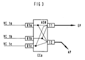
- the redundant path pair (active path AP and substitute path EP) is formed from three virtual connections VC1a, VC1b and VC1c. Message cells occurring in the course of these virtual connections are fed to the coupling device CCa via interface devices R1a, R1b and R1c. These message cells are duplicated in the coupling device CCa according to the principle described above.
- switching devices can also be provided in the ATM communication network shown in FIG. 1 as coupling devices instead of "cross connects", via which the virtual connections belonging to a virtual path pair are only set up in the course of establishing a connection.
Applications Claiming Priority (2)
| Application Number | Priority Date | Filing Date | Title |
|---|---|---|---|
| DE4331577 | 1993-09-16 | ||
| DE4331577A DE4331577C2 (de) | 1993-09-16 | 1993-09-16 | Verfahren und Schaltungsanordnung zum Übertragen von Nachrichtenzellen über redundante virtuelle Pfadpaare eines ATM-Kommunikationsnetzes |
Publications (2)
| Publication Number | Publication Date |
|---|---|
| EP0645918A2 true EP0645918A2 (fr) | 1995-03-29 |
| EP0645918A3 EP0645918A3 (fr) | 1995-12-20 |
Family
ID=6497912
Family Applications (1)
| Application Number | Title | Priority Date | Filing Date |
|---|---|---|---|
| EP94114157A Withdrawn EP0645918A3 (fr) | 1993-09-16 | 1994-09-08 | Procédé et dispositif de circuit pour la transmission de cellules de messages par les paires de voies redondantes virtuelles d'un réseau de communication ATM. |
Country Status (5)
| Country | Link |
|---|---|
| US (1) | US5671215A (fr) |
| EP (1) | EP0645918A3 (fr) |
| JP (1) | JPH07170276A (fr) |
| CA (1) | CA2132063A1 (fr) |
| DE (1) | DE4331577C2 (fr) |
Cited By (2)
| Publication number | Priority date | Publication date | Assignee | Title |
|---|---|---|---|---|
| DE19646016A1 (de) * | 1996-11-07 | 1998-05-20 | Siemens Ag | Verfahren zum Ersatzschalten von Übertragungseinrichtungen zur bidirektionalen Übertragung von ATM-Zellen |
| EP0788259A3 (fr) * | 1996-02-02 | 2001-02-14 | Nec Corporation | Système de routage |
Families Citing this family (36)
| Publication number | Priority date | Publication date | Assignee | Title |
|---|---|---|---|---|
| GB9505722D0 (en) * | 1995-03-21 | 1995-05-10 | Newbridge Networks Corp | Lan bridging redundancy |
| FR2737371A1 (fr) | 1995-07-26 | 1997-01-31 | Trt Telecom Radio Electr | Securisation par doublement d'au moins certaines voies logiques dans un reseau de telecommunications |
| FR2743164B1 (fr) * | 1995-12-28 | 1998-02-06 | Cegelec | Procede pour ordonnancer une pluralite de messages provenant respectivement d'une pluralite de sources, et systeme pour la mise en oeuvre de ce procede |
| US6735168B1 (en) | 1996-06-25 | 2004-05-11 | Nortel Networks Limited | Method and architecture for providing telephony between data networks and PSTN |
| WO1997050277A2 (fr) * | 1996-06-25 | 1997-12-31 | Northern Telecom Limited | Procede et architecture d'etablissement d'un service telephonique entre des reseaux informatiques et des rtpc |
| GB9614987D0 (en) * | 1996-07-17 | 1996-09-04 | Newbridge Networks Corp | High availabilty ATM virtual connections |
| US6275468B1 (en) * | 1996-07-31 | 2001-08-14 | Motorola, Inc. | Automatic timing adjustment for diverse routing of HFC systems |
| US5953312A (en) * | 1996-09-13 | 1999-09-14 | Bay Networks | Method and apparatus for determining alternate routes in a network using a connection-oriented protocol |
| DE19713066C1 (de) * | 1997-03-27 | 1998-10-22 | Siemens Ag | Verfahren zum frühzeitigen Umschalten zwischen redundanten Übertragungsstrecken |
| DE59814195D1 (de) * | 1997-03-27 | 2008-04-30 | Nokia Siemens Networks Gmbh | Redundantes Übertragungssystem mit Abschaltung einer Übertragungsstrecke fehlerhaften Übertragungsverhaltens |
| JP3801740B2 (ja) * | 1997-08-13 | 2006-07-26 | 富士通株式会社 | セル流量制御方法及びこれを用いるセル交換システム |
| JPH11127157A (ja) * | 1997-10-20 | 1999-05-11 | Fujitsu Ltd | Atm交換機 |
| US6088329A (en) * | 1997-12-11 | 2000-07-11 | Telefonaktiebolaget Lm Ericsson | Fault tolerant subrate switching |
| US6272107B1 (en) * | 1998-05-12 | 2001-08-07 | 3Com Corporation | Method of path restoration in an ATM network utilizing point to point switched virtual circuits |
| US6466574B1 (en) * | 1998-06-05 | 2002-10-15 | International Business Machines Corporation | Quality of service improvement of internet real-time media transmission by transmitting redundant voice/media frames |
| JP2000174815A (ja) | 1998-12-09 | 2000-06-23 | Nec Corp | Qosプロテクション装置 |
| US6813242B1 (en) * | 1999-05-07 | 2004-11-02 | Lucent Technologies Inc. | Method of and apparatus for fast alternate-path rerouting of labeled data packets normally routed over a predetermined primary label switched path upon failure or congestion in the primary path |
| US7136350B1 (en) * | 1999-07-12 | 2006-11-14 | Lucent Technologies Inc. | Efficient support for VP/VC groups |
| IL133083A (en) * | 1999-11-22 | 2004-02-08 | Eci Telecom Ltd | Method and system for management of network domains |
| AU2001230971A1 (en) * | 2000-01-20 | 2001-07-31 | Megaxess, Inc. | Address translation table for fast atm protection switching |
| US7463581B1 (en) | 2000-02-07 | 2008-12-09 | Cisco Technology, Inc. | Re-routing connections using redundant path connections and loopbacks |
| US6882626B1 (en) | 2000-06-01 | 2005-04-19 | Cisco Technology, Inc. | System and method for automated switching of data traffic in a packet network |
| US6807149B1 (en) | 2000-07-17 | 2004-10-19 | International Business Machines Corporation | Method and system for LEC resiliency with fast failover |
| US7039007B1 (en) * | 2000-07-31 | 2006-05-02 | Cicso Technology, Inc. | System and method for improving reliability of a packet network |
| FI109855B (fi) * | 2000-08-25 | 2002-10-15 | Nokia Corp | Datavirran suodatus tietoliikenneverkossa |
| US7099327B1 (en) * | 2000-10-12 | 2006-08-29 | Lucent Technologies Inc. | Data communications networks with high performance and reliability |
| US6914878B1 (en) | 2000-10-16 | 2005-07-05 | Telefonaktiebolaget Lm Ericsson (Publ) | Fault detection in multi-plane switch |
| US8428056B2 (en) * | 2000-12-22 | 2013-04-23 | Avaya, Inc. | Generation of redundant scheduled network paths using a branch and merge technique |
| US7027387B2 (en) * | 2001-08-31 | 2006-04-11 | Motorola, Inc. | Vehicle active network with data redundancy |
| US6766482B1 (en) | 2001-10-31 | 2004-07-20 | Extreme Networks | Ethernet automatic protection switching |
| US7747747B1 (en) | 2002-05-06 | 2010-06-29 | Apple Inc. | Method and arrangement for supressing duplicate network resources |
| JP4485309B2 (ja) * | 2004-09-28 | 2010-06-23 | 富士通株式会社 | ネットワーク障害の影響を解析する装置 |
| US7590756B2 (en) * | 2005-05-13 | 2009-09-15 | Itt Manufacturing Enterprises, Inc. | Method and system for transferring data in a communications network using redundant communication paths |
| US7826348B2 (en) * | 2007-04-26 | 2010-11-02 | Cisco Technology, Inc. | Multicast fast reroute |
| US8526300B2 (en) | 2008-03-31 | 2013-09-03 | Ericsson Ab | Method and apparatus for providing resiliency in multicast networks |
| US10243841B2 (en) | 2016-06-06 | 2019-03-26 | Cisco Technology, Inc. | Multicast fast reroute at access devices with controller implemented multicast control plane |
Citations (4)
| Publication number | Priority date | Publication date | Assignee | Title |
|---|---|---|---|---|
| EP0505601A1 (fr) * | 1991-03-28 | 1992-09-30 | Siemens Aktiengesellschaft | Procédé pour transmettre des paquets d'information redondants via des dispositifs de commutation redondants |
| EP0542233A2 (fr) * | 1991-11-15 | 1993-05-19 | Mitsubishi Denki Kabushiki Kaisha | Appareil et procédé pour la commutation de cellules |
| DE4317951C1 (de) * | 1993-05-28 | 1994-05-26 | Siemens Ag | Verfahren und Schaltungsanordnung zur Übertragung von Nachrichtenpaketen nach dem Asynchronen Transfermodus in einem Kommunikationsnetz |
| EP0384936B1 (fr) * | 1989-03-03 | 1994-06-15 | Siemens Aktiengesellschaft | Procédé et dispositif pour transmettre des paquets d'information provenant de lignes d'entrée via un dispositif à communication de paquets |
Family Cites Families (19)
| Publication number | Priority date | Publication date | Assignee | Title |
|---|---|---|---|---|
| JPS536807B2 (fr) * | 1972-02-10 | 1978-03-11 | ||
| FR2410919A1 (fr) * | 1977-12-05 | 1979-06-29 | Telecommunications Sa | Procede d'appreciation de la qualite d'un faisceau hertzien numerique |
| JPS55136742A (en) * | 1979-04-13 | 1980-10-24 | Toshiba Corp | Multiplex communication system |
| US4242756A (en) * | 1979-05-21 | 1980-12-30 | Rockwell International Corporation | Multiline switching protection apparatus |
| DE3145893C2 (de) * | 1981-11-19 | 1983-10-06 | Siemens Ag, 1000 Berlin Und 8000 Muenchen | Anordnung zur Auswahl einer von zwei das gleiche Digitalsignal führenden Übertragungsstrecken |
| JPS60254928A (ja) * | 1984-05-31 | 1985-12-16 | Nec Corp | セツト・スタンバイ通信方式 |
| US4692918A (en) * | 1984-12-17 | 1987-09-08 | At&T Bell Laboratories | Reliable local data network arrangement |
| DE3513165A1 (de) * | 1985-04-12 | 1986-10-16 | Siemens AG, 1000 Berlin und 8000 München | Schaltungsanordnung fuer fernmeldevermittlungsanlagen, insbesondere fernsprechvermittlungsanlagen, mit einrichtungen zur funktionsfaehigkeitspruefung durchgeschalteter verbindungen |
| GB2222055B (en) * | 1988-08-16 | 1992-10-28 | Plessey Telecomm | Telecommunications transmission security arrangement |
| DE4090614C2 (de) * | 1989-04-19 | 1999-08-26 | Hitachi Cable | Netzwerk vom Doppelbustyp |
| US5185736A (en) * | 1989-05-12 | 1993-02-09 | Alcatel Na Network Systems Corp. | Synchronous optical transmission system |
| US4964120A (en) * | 1989-09-08 | 1990-10-16 | Honeywell Inc. | Method of detecting a cable fault and switching to a redundant cable in a universal local area network |
| EP0462540B1 (fr) * | 1990-06-18 | 2000-08-30 | Fujitsu Limited | Système de retour pour un réseau ATM |
| JP2558012B2 (ja) * | 1990-11-27 | 1996-11-27 | 富士通株式会社 | 通信回線バックアップ方式 |
| JP2578704B2 (ja) * | 1991-03-26 | 1997-02-05 | 日本電信電話株式会社 | リング伝送網のループバック方法およびリング伝送装置 |
| US5398235A (en) * | 1991-11-15 | 1995-03-14 | Mitsubishi Denki Kabushiki Kaisha | Cell exchanging apparatus |
| US5485465A (en) * | 1992-05-20 | 1996-01-16 | The Whitaker Corporation | Redundancy control for a broadcast data transmission system |
| US5345445A (en) * | 1992-11-06 | 1994-09-06 | At&T Bell Laboratories | Establishing telecommunications calls in a broadband network |
| US5404350A (en) * | 1993-04-22 | 1995-04-04 | At&T Corp. | Routing calls destined for inaccessible destinations |
-
1993
- 1993-09-16 DE DE4331577A patent/DE4331577C2/de not_active Expired - Fee Related
-
1994
- 1994-09-08 EP EP94114157A patent/EP0645918A3/fr not_active Withdrawn
- 1994-09-09 US US08/303,523 patent/US5671215A/en not_active Expired - Fee Related
- 1994-09-12 JP JP6217545A patent/JPH07170276A/ja not_active Ceased
- 1994-09-14 CA CA002132063A patent/CA2132063A1/fr not_active Abandoned
Patent Citations (4)
| Publication number | Priority date | Publication date | Assignee | Title |
|---|---|---|---|---|
| EP0384936B1 (fr) * | 1989-03-03 | 1994-06-15 | Siemens Aktiengesellschaft | Procédé et dispositif pour transmettre des paquets d'information provenant de lignes d'entrée via un dispositif à communication de paquets |
| EP0505601A1 (fr) * | 1991-03-28 | 1992-09-30 | Siemens Aktiengesellschaft | Procédé pour transmettre des paquets d'information redondants via des dispositifs de commutation redondants |
| EP0542233A2 (fr) * | 1991-11-15 | 1993-05-19 | Mitsubishi Denki Kabushiki Kaisha | Appareil et procédé pour la commutation de cellules |
| DE4317951C1 (de) * | 1993-05-28 | 1994-05-26 | Siemens Ag | Verfahren und Schaltungsanordnung zur Übertragung von Nachrichtenpaketen nach dem Asynchronen Transfermodus in einem Kommunikationsnetz |
Cited By (4)
| Publication number | Priority date | Publication date | Assignee | Title |
|---|---|---|---|---|
| EP0788259A3 (fr) * | 1996-02-02 | 2001-02-14 | Nec Corporation | Système de routage |
| US6272111B1 (en) | 1996-02-02 | 2001-08-07 | Nec Corporation | Routing system |
| DE19646016A1 (de) * | 1996-11-07 | 1998-05-20 | Siemens Ag | Verfahren zum Ersatzschalten von Übertragungseinrichtungen zur bidirektionalen Übertragung von ATM-Zellen |
| DE19646016C2 (de) * | 1996-11-07 | 1999-10-14 | Siemens Ag | Verfahren zum Ersatzschalten von Übertragungseinrichtungen zur bidirektionalen Übertragung von ATM-Zellen |
Also Published As
| Publication number | Publication date |
|---|---|
| DE4331577C2 (de) | 1995-12-07 |
| US5671215A (en) | 1997-09-23 |
| EP0645918A3 (fr) | 1995-12-20 |
| CA2132063A1 (fr) | 1995-03-17 |
| DE4331577A1 (de) | 1995-03-23 |
| JPH07170276A (ja) | 1995-07-04 |
Similar Documents
| Publication | Publication Date | Title |
|---|---|---|
| EP0645918A2 (fr) | Procédé et dispositif de circuit pour la transmission de cellules de messages par les paires de voies redondantes virtuelles d'un réseau de communication ATM | |
| EP0645919A2 (fr) | Procédé pour la transmission de cellules de messages par les paires de voies redondantes virtuelles d'un réseau de communication ATM | |
| EP0384936B1 (fr) | Procédé et dispositif pour transmettre des paquets d'information provenant de lignes d'entrée via un dispositif à communication de paquets | |
| EP0453607B1 (fr) | Méthode et dispositif pour réduire la perte de paquets d'information, transmis par un commutateur de paquets | |
| EP0470283B1 (fr) | Méthode et dispositif pour déterminer la qualité de circuits virtuels transitant par un dispositif de commutation ATM | |
| DE19532422C1 (de) | Lokales, nach dem asynchronen Transfermodus (ATM) arbeitendes Netzwerk mit wenigstens zwei Ringsystemen | |
| EP0566961B1 (fr) | Procédé et circuit pour faire respecter le débit de transmission préaccordé dans un dispositif de commutation ATM | |
| EP0645913A2 (fr) | Procédé et dispositif pour transmettre des cellules ATM sur des chemins virtuels | |
| EP0170336B1 (fr) | Montage pour la transmission d'informations, à reconfiguration | |
| EP0419959B1 (fr) | Circuit pour contrÔler le respet de débits préétablis lors de la transmission de cellules de données | |
| EP0342547A1 (fr) | Procédé pour la génération d'un signal pour supprimer un alarme | |
| DE4434724C1 (de) | Verfahren und Schaltungsanordnung zum Weiterleiten von einer ATM-Kommunikationseinrichtung zugeführten Nachrichtenzellen | |
| EP0682422A2 (fr) | Méthode et dispositif pour synchroniser un train de cellules transmis avec redondance | |
| EP0453606A1 (fr) | Méthode et dispositif pour réduire la perte de paquets d'information, transmis par un commutateur de paquets | |
| EP1130853A1 (fr) | Dispositif de circuit pour la commutation de substitution d' installations de transmission dans des architectures d' anneau avec des paquets de MPLS | |
| DE2854655C2 (de) | Signalübertragungs-Steueranordnung | |
| EP0751693A2 (fr) | Réseau de communication ATM | |
| EP0572831B1 (fr) | Méthode pour surveiller la participation et réduire les erreurs de bit pour communications commutées dans un système numérique | |
| EP0513511B1 (fr) | Procédé pour le contrÔle de l'admissibilité d'établissement des connexions virtuelles | |
| EP0582848A2 (fr) | Procédé de détection d'erreurs dans des systèmes de communication numériques | |
| DE4446248C2 (de) | Übertragungssystem | |
| EP0173274B1 (fr) | Méthode et montage pour la réalisation et la maintenance d'une liaison à division temporelle à large bande | |
| EP0732828B1 (fr) | Réseau de communication optimisé en redondance pour la transmission de signaux de données | |
| EP0720411B1 (fr) | Méthode et système pour la surveillance d'un courant de cellules ATM | |
| EP0584387B1 (fr) | Procédé et circuit pour surveiller l'agencement de cellules pendant la transmission des cellules d'information |
Legal Events
| Date | Code | Title | Description |
|---|---|---|---|
| PUAI | Public reference made under article 153(3) epc to a published international application that has entered the european phase |
Free format text: ORIGINAL CODE: 0009012 |
|
| AK | Designated contracting states |
Kind code of ref document: A2 Designated state(s): AT BE CH FR GB IT LI NL SE |
|
| PUAL | Search report despatched |
Free format text: ORIGINAL CODE: 0009013 |
|
| AK | Designated contracting states |
Kind code of ref document: A3 Designated state(s): AT BE CH FR GB IT LI NL SE |
|
| RHK1 | Main classification (correction) |
Ipc: H04L 12/56 |
|
| 17P | Request for examination filed |
Effective date: 19960104 |
|
| 17Q | First examination report despatched |
Effective date: 20000714 |
|
| STAA | Information on the status of an ep patent application or granted ep patent |
Free format text: STATUS: THE APPLICATION IS DEEMED TO BE WITHDRAWN |
|
| 18D | Application deemed to be withdrawn |
Effective date: 20020802 |