EP0535614A2 - Sonnenzellenmodul - Google Patents
Sonnenzellenmodul Download PDFInfo
- Publication number
- EP0535614A2 EP0535614A2 EP92116686A EP92116686A EP0535614A2 EP 0535614 A2 EP0535614 A2 EP 0535614A2 EP 92116686 A EP92116686 A EP 92116686A EP 92116686 A EP92116686 A EP 92116686A EP 0535614 A2 EP0535614 A2 EP 0535614A2
- Authority
- EP
- European Patent Office
- Prior art keywords
- solar battery
- battery module
- bypass diode
- diode
- cells
- Prior art date
- Legal status (The legal status is an assumption and is not a legal conclusion. Google has not performed a legal analysis and makes no representation as to the accuracy of the status listed.)
- Granted
Links
Images


Classifications
-
- H—ELECTRICITY
- H10—SEMICONDUCTOR DEVICES; ELECTRIC SOLID-STATE DEVICES NOT OTHERWISE PROVIDED FOR
- H10F—INORGANIC SEMICONDUCTOR DEVICES SENSITIVE TO INFRARED RADIATION, LIGHT, ELECTROMAGNETIC RADIATION OF SHORTER WAVELENGTH OR CORPUSCULAR RADIATION
- H10F19/00—Integrated devices, or assemblies of multiple devices, comprising at least one photovoltaic cell covered by group H10F10/00, e.g. photovoltaic modules
- H10F19/70—Integrated devices, or assemblies of multiple devices, comprising at least one photovoltaic cell covered by group H10F10/00, e.g. photovoltaic modules comprising bypass diodes
- H10F19/75—Integrated devices, or assemblies of multiple devices, comprising at least one photovoltaic cell covered by group H10F10/00, e.g. photovoltaic modules comprising bypass diodes the bypass diodes being integrated or directly associated with the photovoltaic cells, e.g. formed in or on the same substrate
-
- H—ELECTRICITY
- H10—SEMICONDUCTOR DEVICES; ELECTRIC SOLID-STATE DEVICES NOT OTHERWISE PROVIDED FOR
- H10F—INORGANIC SEMICONDUCTOR DEVICES SENSITIVE TO INFRARED RADIATION, LIGHT, ELECTROMAGNETIC RADIATION OF SHORTER WAVELENGTH OR CORPUSCULAR RADIATION
- H10F19/00—Integrated devices, or assemblies of multiple devices, comprising at least one photovoltaic cell covered by group H10F10/00, e.g. photovoltaic modules
- H10F19/80—Encapsulations or containers for integrated devices, or assemblies of multiple devices, having photovoltaic cells
-
- H—ELECTRICITY
- H10—SEMICONDUCTOR DEVICES; ELECTRIC SOLID-STATE DEVICES NOT OTHERWISE PROVIDED FOR
- H10F—INORGANIC SEMICONDUCTOR DEVICES SENSITIVE TO INFRARED RADIATION, LIGHT, ELECTROMAGNETIC RADIATION OF SHORTER WAVELENGTH OR CORPUSCULAR RADIATION
- H10F19/00—Integrated devices, or assemblies of multiple devices, comprising at least one photovoltaic cell covered by group H10F10/00, e.g. photovoltaic modules
- H10F19/90—Structures for connecting between photovoltaic cells, e.g. interconnections or insulating spacers
- H10F19/902—Structures for connecting between photovoltaic cells, e.g. interconnections or insulating spacers for series or parallel connection of photovoltaic cells
-
- Y—GENERAL TAGGING OF NEW TECHNOLOGICAL DEVELOPMENTS; GENERAL TAGGING OF CROSS-SECTIONAL TECHNOLOGIES SPANNING OVER SEVERAL SECTIONS OF THE IPC; TECHNICAL SUBJECTS COVERED BY FORMER USPC CROSS-REFERENCE ART COLLECTIONS [XRACs] AND DIGESTS
- Y02—TECHNOLOGIES OR APPLICATIONS FOR MITIGATION OR ADAPTATION AGAINST CLIMATE CHANGE
- Y02B—CLIMATE CHANGE MITIGATION TECHNOLOGIES RELATED TO BUILDINGS, e.g. HOUSING, HOUSE APPLIANCES OR RELATED END-USER APPLICATIONS
- Y02B10/00—Integration of renewable energy sources in buildings
- Y02B10/10—Photovoltaic [PV]
-
- Y—GENERAL TAGGING OF NEW TECHNOLOGICAL DEVELOPMENTS; GENERAL TAGGING OF CROSS-SECTIONAL TECHNOLOGIES SPANNING OVER SEVERAL SECTIONS OF THE IPC; TECHNICAL SUBJECTS COVERED BY FORMER USPC CROSS-REFERENCE ART COLLECTIONS [XRACs] AND DIGESTS
- Y02—TECHNOLOGIES OR APPLICATIONS FOR MITIGATION OR ADAPTATION AGAINST CLIMATE CHANGE
- Y02E—REDUCTION OF GREENHOUSE GAS [GHG] EMISSIONS, RELATED TO ENERGY GENERATION, TRANSMISSION OR DISTRIBUTION
- Y02E10/00—Energy generation through renewable energy sources
- Y02E10/50—Photovoltaic [PV] energy
Definitions
- the present invention relates generally to a solar battery module including a plurality of solar battery cells which are electrically series-connected and, more particularly, to improvements of a solar battery module including a bypass diode allowing output currents of solar battery cells to be bypassed.
- a solar battery module 1A includes a plurality of solar battery cells 2 which are electrically series-connected by an interconnector 3 so as to obtain a desired output voltage.
- the solar battery module 1A having such structure that the plurality of solar battery cells 2 are series-connected, however, even in a case where one solar battery cell 2 in the module is shaded, whereas other cells 2 are unshaded, the solar battery module 1A is greatly affected by the single shaded cell 2, resulting in a substantial decrease in the output of the entire module 1A.
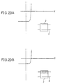
- Figs. 20A and 20B show output voltage-current (V-I) characteristics of one solar battery cell 2.
- a horizontal axis represents a voltage V
- a longitudinal axis represents a current I.
- Fig. 20A shows V-I characteristics provided when one overall solar battery cell 2 is irradiated with light
- Fig. 20B shows V-I characteristics provided when about a half of one solar battery cell 2 is shaded.
- the output current I of the half-shaded solar battery cell 2 decreases to approximately a half of the cell 2 which is entirely irradiated with light.
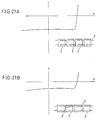
- Figs. 21A and 21B are similar to Figs. 20A and 20B and show V-I characteristics of one overall solar battery module 1A.
- Fig. 21A shows V-I characteristics provided when all of the solar battery cells 2 in the module 1A are irradiated with light
- Fig. 21B shows V-I characteristics provided when approximately a half of one solar battery cell 2 in the module 1A is shaded.
- the solar battery module 1A is under such an influence that the output current I of the entire module 1A decreases to approximately a half.
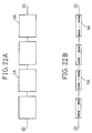
- FIGs. 22A and 22B one example of a solar battery system in which a plurality of solar battery modules 1A are further series-connected is schematically shown.
- Figs. 22A and 22B show, respectively, a block diagram and an equivalent circuit diagram of that solar battery system. In this solar battery system also, even if only one of the solar battery cells in the system is shaded, the same output decrease as shown in Fig. 21B occurs.
- a large reverse bias voltage is applied to a shaded solar battery cell, so that the shaded cell is destroyed depending on some external circuit connected with the solar battery module or the solar battery system.
- solar battery cells are overheated by the reverse bias voltage, causing a fire in a case with a solar battery module installed on a roof.
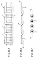
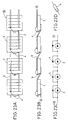
- Figs. 23A, 23B and 23C are similar to Figs. 19A, 19B and 19C and illustrate one example of a solar battery module incorporating a bypass diode according to prior art.
- Figs. 23A, 23B and 23C show, respectively, a top plan view, a longitudinal cross-sectional view and an equivalent circuit diagram of a solar battery module 1B.
- Fig. 23D is a perspective view showing one bypass diode.
- bypass diodes 4 are connected in parallel in reverse polarity with respect to respective solar battery cells 2 included in the module 1B.
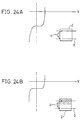
- Figs. 24A, 24B, 25A and 25B are similar to Figs. 20A, 20B, 21A and 21B, respectively, and show output V-I characteristics in the solar battery module 1B of Fig. 23A.
- Figs. 24A and 24B show output V-I characteristics of one solar battery cell 2 incorporating a bypass diode 4.
- the bypass diode 4 when there is one solar battery cell 2, the bypass diode 4 does not reduce a decrease in the output of the shaded solar battery cell 2.
- the bypass diode 4 can act to release the reverse bias voltage and protect the solar battery cell 2 from breakage due to the reserve bias voltage.
- Fig. 25A shows V-I characteristics provided when all of the solar battery cells 2 in the solar battery module 1B of Fig. 23A are irradiated with light
- Fig. 25B shows V-I characteristics provided when approximately a half of one solar battery cell 2 in the module 1B is shaded.
- bypass diode 4 can act to minimize a decrease in the output of the entire module 1B when a part of solar battery cells 2 in the solar battery module 1B are shaded.
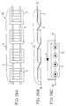
- FIGs. 26A, 26B and 26C show, respectively, a top plan view, a longitudinal cross-sectional view and an equivalent circuit diagram of a solar battery module 1C.
- the solar battery module 1C including a desired number of series-connected solar battery cells 2 includes one bypass diode 4 connected in parallel in a reverse polarity to the solar battery module 1C.
- this bypass diode 4 does not reduce a decrease in the output of the entire module 1C; however, when a reverse bias voltage acts on the module 1C, the bypass diode 4 can act to protect the entire module 1C from breakdown due to the applied reverse bias voltage.
- a solar battery system including one bypass diode for each solar battery module is schematically illustrated.
- Figs. 27A and 27B show, respectively, a block diagram and an equivalent circuit diagram of that solar battery system.
- This solar battery system includes a plurality of series-connected solar battery modules 1C, each solar battery module 1C including one bypass diode 4.
- Those bypass diodes 4 can act to reduce a decrease in the output of the entire solar battery system even in a case where a part of solar battery cells in the solar battery modules 1C are shaded.
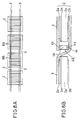
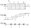
- FIGs. 28A, 28B and 28C show, respectively, a top view, a longitudinal cross-section view and an equivalent circuit diagram of a solar battery module 1D.
- the module ID of Figs. 28A, 28B and 28C is similar to the module 1A of Figs. 19A, 19B and 19C; however, with reference to Figs.
- a plurality of relatively small solar battery cells 2 each having a comb tooth-like front electrode 2a are electrically series-connected in such a manner that a portion of each solar battery cell 2 is overlapped with a portion of each adjacent cell 2, a so-called roof-tile-stacked manner.
- a back electrode (not shown) is formed on an approximately overall back surface of each of those small solar battery cells 2, and a portion of the front electrode 2a of one solar battery cell 2 is directly attached to the back electrode of its adjacent solar battery cell 2.
- Solar battery cells 2 on opposite ends of a series of the roof-tile-stacked solar battery cells 2 are connected with interconnecters 3.
- a crack is liable to be produced in a direction orthogonal to an elongated direction of that module, as illustrated in Figs. 29A and 29B.
- This crack is liable to be produced particularly in a long solar battery module in which a large number of solar battery cells 2 are connected in series.
- Figs. 29A and 29B show, respectively, a top view and a longitudinal cross-sectional view of the solar battery module 1D including a cracked solar battery cell 2.
- the diode 4 of the type shown in Fig. 23D is employed in the solar battery module incorporating the prior art bypass diode 4.
- This diode 4 has usually a cylindrical form of approximately 3-4mm in diameter and approximately 10mm in length.
- the solar battery cell 2 has a thin plate form of, e.g., 100 x 100 x 0.4mm3 in size.
- the thin solar battery cell 2 when the solar battery module is laminated with and interposed between protection layers, the thin solar battery cell 2 sometimes cracks by being pressed by the thick diode 4.
- the overall laminated solar battery module becomes thick due to the thick diode 4, resulting in an increase in the overall weight of the module.
- the diode 4 is provided in portions other than the solar batter cell, the size of the entire solar battery module becomes increased by the proportion corresponding to the provision of the diode 4, and a module conversion efficiency (a photoelectric conversion efficiency of the module with respect to an outer size of the module) becomes decreased, resulting in a deterioration in the appearance of the product and a degradation in the value of the commodity.
- a laminating step since the diode 4 is thick, a laminating step becomes complicated, resulting in a higher cost of the product.
- one object of the present invention is to provide a solar battery module which has a good appearance and a high value as a commodity and can be easily thinly laminated together with protection layers at a low cost without damaging thin solar battery cells.
- Another object of the present invention is to provide a solar battery module in which even if a crack is produced in a roof-tile-stacked solar battery module, an output of the module does not decrease to 0 but can be maintained at a very high level.
- a solar battery module includes a plurality of solar battery cells which are electrically series-connected by interconnectors, and one or more diodes which allow output currents of the solar battery cells to be bypassed with respect to one or more solar battery cells, wherein those diodes are pellet-like thin diodes and are attached on electrodes of the solar battery cells on a line in which the interconnectors are aligned.
- a solar battery module includes a plurality of solar battery cells, interconnectors for electrically series-connecting the plurality of solar battery cells, and one or more bypass diodes which allow output currents of the solar battery cells to be bypassed with respect to the solar battery cells, wherein those bypass diodes are pellet-like thin diodes and connected between two interconnectors extending over from a front electrode and a back electrode of a solar battery cell to be bypassed.
- a solar battery module includes a plurality of solar battery cells which are electrically series-connected, and one or more bypass diodes which allow output currents of the solar battery cells to be bypassed with respect to the plurality of solar battery cells, wherein cells of the plurality of series-connected solar battery cells to be bypassed, which are on opposite ends are disposed in close proximity to each other, and the bypass diodes are pellet-like thin diodes and attached on an electrode of one of the cells on the opposite ends.
- a solar battery module includes a plurality of solar battery cells which are electrically connected in series by roof-tile-stacking, and one or more bypass diodes which allow output currents of those solar battery cells to be bypassed with respect to one or more solar battery cells, wherein those bypass diodes are pellet-like thin diodes and attached on back electrodes of the solar battery cells.
- pellet-like diodes which are as thin as solar battery cells are directly attached as bypass diodes on the electrode of the solar battery cells or on the interconnectors, it is possible to provide a solar battery module which has a good appearance and a high value as commodities and can be thinly laminated together with protection layers easily at a low cost without damaging thin solar battery cells.
- the output of the solar battery module does not decrease to 0 and a decrease of the output can be inhibited to a minimum extent.
- Figs. 1A, 1B and 1C are diagrams schematically showing one example of a solar battery cell for use in a solar battery module of the present invention.
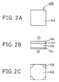
- Figs. 2A, 2B and 2C are diagrams schematically showing one example of a pellet-like thin bypass diode for use in the solar battery module of the present invention.
- Figs. 3A, 3B and 3C are diagrams showing the step of attaching a bypass diode on an electrode of a solar battery cell according to one embodiment of the present invention.
- Figs. 4A and 4B are diagrams showing the step of connecting an interconnector on the electrode of the solar battery cell according to one embodiment of the present invention.
- Figs. 5A, 5B and 5C are diagrams showing the step of attaching a diode interconnector on the bypass diode according to one embodiment of the present invention.
- Figs. 6A and 6B are diagrams showing a solar battery module in which a plurality of solar battery cells are series-connected by interconnectors according to one embodiment of the present invention.
- Figs. 7A, 7B and 7C are diagrams showing the step of laminating the solar battery module together with protection layers according to one embodiment of the present invention.
- Figs. 8A and 8B are diagrams showing a solar battery module according to another embodiment of the present invention.
- Figs. 9A and 9B are diagrams showing a solar battery module according to a further embodiment of the present invention.
- Figs. 10A and 10B are diagrams showing a solar battery module according to a still further embodiment of the present invention.
- Figs. 11A and 11B are diagrams showing a solar battery module according to a still further embodiment of the present invention.
- Figs. 12A and 12B are diagrams showing a solar battery module according to a still further embodiment of the present invention.
- Figs. 13A and 13B are diagrams showing a solar battery module according to a still further embodiment of the present invention.
- Fig. 14 is an equivalent circuit diagram showing a solar battery module according to a still further embodiment of the present invention.
- Figs. 15A, 15B, 15C and 15D are diagrams showing a roof-tile-stacked solar battery module according to a still further embodiment of the present invention.
- Figs. 16A, 16B and 16C are diagrams showing the state where a crack is produced in the roof-tile-stacked solar battery module of Figs 15A, 15B and 15C.
- Figs. 17A, 17B and 17C are diagrams showing the step of assembling the roof-tile-stacked solar battery module of Fig. 15C.
- Fig. 18 is a diagram showing a roof-tile-stacked solar battery module according to a still further embodiment of the present invention.
- Figs. 19A, 19B and 19C are diagrams showing one example of a conventional solar battery module.
- Figs. 20A and 20B are diagrams showing output voltage-current (V-I) characteristics of one solar battery cell.
- Figs. 21A and 21B are diagrams showing V-I characteristics of one entire solar battery module.
- Figs. 22A and 22B are diagrams showing one example of a conventional solar battery system including a plurality of solar battery modules.
- Figs. 23A, 23B and 23C are diagrams showing one example of a solar battery module incorporating a prior art bypass diode.
- Figs. 24A and 24B are diagrams showing V-I characteristics of one prior art solar battery cell including a bypass diode.
- Figs. 25A and 25B are diagrams showing V-I characteristics in one prior art solar battery module including a bypass diode.
- Figs. 26A, 26B and 26C are diagrams showing one example of a prior art solar battery module including only one bypass diode.
- Figs. 27A and 27B are diagrams showing a prior art solar battery system including one bypass diode for each solar battery module.
- Figs. 28A, 28B and 28C are diagrams showing a conventional roof-tile-stacked solar battery module.
- Figs. 29A and 29B are diagrams showing the state where a crack is produced in the roof-tile-stacked solar battery module of Figs. 28A and 28B.
- a solar battery cell for use in a solar battery module according to one embodiment of the present invention is schematically illustrated.
- Figs. 1A and 1B are, respectively, a top plan view and a bottom plan view of the solar battery cell; and
- Fig. 1C is a cross-sectional view taken along a line 1C-1C of Fig. 1A.
- an n type semiconductor layer 2n is formed on one main surface of a p type semiconductor substrate 2p.
- a front electrode 2a is formed on the n type layer 2n, while a back electrode 2b is formed on the other main surface of the p type substrate 2p.
- the solar battery cell 2 is of a thin plate form having a size of, e.g. 100 x 100 x 0.4mm3.
- a pellet-like bypass diode employed in a solar battery module is schematically illustrated.
- Figs. 2A, 2B and 2C are, respectively, a top plan view, a side view and a bottom view of the pellet-like diode.
- an n type semiconductor layer 4n is formed on one main surface of a p type semiconductor substrate 4p.
- a front electrode 4a is formed on the n type layer 4n, while a back electrode 4b is formed on the other main surface of the p type substrate.
- the back electrode 4b has a different shape from that of the front electrode 4a so as to easily distinguish the front and the back of the diode 4A.
- Those front and back electrodes 4a and 4b are coated with solder.
- This pellet-like diode 4A is of a thin plate form having a size of, e.g., 3 x 3 x 0.4mm3. That is, the pellet-like diode 4A has a thickness of 0.4mm far smaller than a thickness 3-4mm of the conventional diode 4 shown in Fig. 23D.
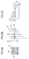
- Figs. 3A, 3B and 3C the step of attaching a bypass diode on an electrode of a solar battery cell is illustrated.
- the pellet-like diode 4A is mounted on one end of the front electrode 2a of the solar battery cell 2, then heated and soldered thereon.
- Fig. 3B is a partially enlarged view of the solar battery cell 2 with the pellet-like diode 4A attached thereon; and
- Fig. 3C is an enlarged cross-sectional view taken along a line 3C-3C of Fig. 3B.
- Fig. 4A shows the solar battery cell 2 on which the pellet-like diode 4A and the interconnector 3 are attached; and Fig. 4B is a partially enlarged view of Fig. 4A.
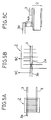
- FIG. 5A an interconnector 3a for electrically connecting the bypass diode 4A is soldered on the diode 4A.
- Fig. 5B is a partially enlarged view of the solar battery cell 2 with the diode interconnector 3a attached on the bypass diode 4A; and
- Fig. 5C is an enlarged cross-section view taken along a line 5C-5C of Fig. 5B. While the diode interconnector 3a is attached after the diode 4A is attached on the solar battery cell 2 in this embodiment, the diode 4A may be attached on the solar battery cell 2 after the diode interconnector 3a is attached in advance on the diode 4A.
- Fig. 6A is a front view of a solar battery cell module in which a plurality of solar battery cells 2 are series-connected.
- Fig. 6B is an enlarged cross-sectional view taken along a line 6B-6B of Fig. 6A.
- each of the solar battery cells 2 includes the bypass diode 4A connected on its front electrode 2a.
- the bypass diode 4A is connected to the front electrode 2a of any adjacent solar battery cell 2 by the diode interconnector 3a.
- Fig. 7A the solar battery module of Fig. 6A is laminated with and interposed between protection layers.
- Fig. 7B is an enlarged cross sectional view taken along a line 7B-7B of Fig. 7A.
- the solar battery cell 2 is interposed between filling resin layers 5 such as of an EVA resin and transparent films 6 on the outside of the filling resin layers 5. After that, these protection layers 5 and 6 are heated under pressure. Consequently, the solar battery cell 2 is laminated with the protection layers 5 and 6 adhering each other as shown in Fig. 7C, thereby completing a solar battery module 10.
- bypass diode 4A is directly connected to a solar battery cell plate, it is possible to allow a heat generated when a current flows through the bypass diode 4A to efficiently escape through the solar battery cell plate, and thus prevent overheating of the bypass diode 4A.
- the pellet-like bypass diode 4A has a thickness of 0.4mm far smaller than the thickness 3-4mm of the conventional normal diode, the above-described laminated solar battery cell does not become thick, or the thin solar battery cell 2 is not damaged by being pressed by the conventional thick bypass diode. Moreover, since the thin pellet-like bypass diode is aligned along the interconnector 3, the finished solar battery module 10 has a good appearance and a high value as commodities.
- Fig. 8A shows a front view of a solar battery module according to another embodiment of the present invention.
- Fig. 8B shows an enlarged cross-sectional view taken along a line 8B-8B of Fig. 8A.
- a pellet-like bypass diode 4A is attached in parallel with each of solar battery cells 2 and between interconnectors 3 which are attached, respectively, on a front and a back of each solar battery cell 2.
- the bypass diode 4A has a thickness of approximately 0.4mm identical to that of the solar battery cell 2, the bypass diode 4A does not increase the thickness of the solar battery module.
- bypass diode 4A does not apply an undesired force to the solar battery cell 2 during pressure attachment at that time.
- a pellet-like bypass diode 4A is attached on a back electrode 2b of one solar battery cell 2.
- An interconnector 3 for series-connecting a plurality of solar battery cells 2 is attached on a front electrode of that solar battery cell 2, and a bypass interconnector 3b is attached on a lower electrode 4b of the bypass diode 4A.
- Fig. 9B shows a solar battery module including a plurality of solar battery cells 2 which are electrically connected by the interconnectors 3 and 3b.
- the bypass interconnector 3b is electrically insulated from the other interconnector 3 or the like by an insulating sheet 7.
- Fig. 9B when a reverse bias voltage is generated in this solar battery module, not each of individual solar battery cells 2 but one entire solar battery module is bypassed via the bypass diode 4A and the bypass interconnector 3b.
- the solar battery module of Fig. 9B is also laminated together with the same protection layers as described in association with Figs. 7A, 7B and 7C.
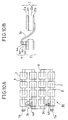
- FIG. 10A With reference to Figs. 10A and 10B, still another embodiment is illustrated.
- a solar battery module 10 of Fig. 10A 16 solar battery cells 2 arranged in a matrix of 4 rows and 4 columns are series-connected between two output terminals 1a.
- Fig. 10B shows an enlarged cross-sectional view of an encircled part in Fig. 10A.
- a pellet-like bypass diode 4A attached on a front electrode 2a of one solar battery cell 2 is connected to a back electrode of another solar battery cell 2 on its adjacent row by a diode interconnector 3c. That is, in the solar battery module of Fig.
- Every two-row solar battery cells 2, i.e., 8 solar battery cells 2 are bypassed via the diode 4A and the diode interconnector 3c.
- the interconnector 3c since the diode interconnector 3c is connected to its adjacent solar battery cell 2, the interconnector 3c can be made far shorter than the bypass interconnector 3b shown in Fig. 9B, and does not require any insulating sheet 7.
- the solar battery module of Fig. 10A is also laminated together with the same protection layers as described in association with Figs. 7A, 7B and 7C.
- a diode interconnector 3d is connected to a front electrode not a back electrode of an adjacent solar battery cell 2 of a solar battery cell 2 on which a bypass diode 4A is mounted.
- the diode interconnector 3d is connected on a top surface of each of the diode and the solar battery cell 2, the step of attaching the diode interconnector 3d is made easier.
- the solar battery cell 2 in which the diode interconnector is attached on its front electrode 2a is not allowed to be bypassed; however, the number of such cells is only two out of 16 cells included in the module, and hence, a sufficiently meaningful bypass function can be exhibited in practice.
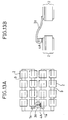
- FIGs. 12A and 12B still another embodiment is illustrated.
- This embodiment is similar to that of Figs. 10A and 10B, but a solar battery module 10 has only one bypass diode 4A. That is, as will be apparent from Figs. 10A and 10B, two cells 2 which are on opposite ends of series-connected solar battery cells 2 and are directly connected to two output terminals 1a are arranged adjacently, and a bypass circuit is formed between these two cells 2 on the opposite ends. Thus, when a reverse bias voltage is generated, the entire solar battery module 10 is bypassed.
- a diode interconnector 3f is connected to a front electrode not a back electrode of an adjacent solar battery cell 2 of a solar battery cell 2 on which a bypass diode 4A is mounted.
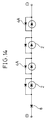
- any solar battery module may include a diode 8 for preventing a reverse current as exemplified in the equivalent circuit diagram of Fig. 14.
- This reverse current preventing diode 8 is a pellet-like diode and may be attached on a solar battery cell 2 on one end of a plurality of series-connected solar battery cells 2.
- bypass diodes may be mounted at two or more places on one solar battery cell, thereby enabling a reduction in a resistance developed when a current flows through the bypass diodes.
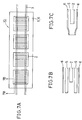
- Figs. 15A, 15B, 15C and 15D show, respectively, a bottom view, a top view, a longitudinal cross-sectional view and an equivalent circuit diagram of a solar battery module according to still another embodiment of the present invention.
- each of solar battery cells 2 having a comb tooth-like front electrode 2a has a thin plate form and a relatively small size of, e.g., 30 x 30 x 0.4mm3, and a back electrode (not shown) is formed on an approximately entire back surface of each cell.
- the plurality of solar battery cells 2 are roof-tile-stacked with portions of the respective cells 2 being overlapped with each other, whereby a part of the front electrode 2a is directly connected to the back electrode of an adjacent solar battery cell 2.
- the solar battery module 1F of Figs. 15A and 15C further includes pellet-like bypass diodes 4A each having a thin plate form of a relatively small size of, e.g., 3 x 3 x 0.4mm3.
- Each bypass diode 4A is disposed in an edge portion of the solar battery cell 2 to be bypassed by that bypass diode, and one main surface of the pellet-like diode 4A is attached onto the back electrode of an adjacent cell 2 of the solar battery cell 2 to be bypassed.
- the other main surface of the bypass diode 4A is attached onto an interconnector 3g which extends and is soldered on the back electrode of the solar battery cell 2 to be bypassed by that diode 4A.
- Figs. 16A, 16B and 16C illustrate the state where a crack 2K is produced in one of the solar battery cells 2 in the solar battery module 1F of Figs. 15A, 15B and 15C.
- Figs 16A, 16B and 16C show, respectively, a bottom view, a top view and a longitudinal cross-sectional view.
- a photovoltaic force applied from a hatched area 2F in Fig. 16B can still contribute to the output of the solar battery module 1F even in the solar battery cell 2 having the crack 2K produce therein.
- FIG. 17A solar battery cells 2 are arranged in a roof-tile-stacked manner on, e.g., an aluminum plate 11 with the back surfaces of the cells facing upward.
- pellet-like bypass diodes 4A are attached onto step portions of the roof-tile-stacking, and interconnectors 3g cut in an appropriate length are extended over the back electrode from the diodes 4A to the solar battery cells 2.
- the solar battery module is placed on a hot plate heated to two hundred and several tens°C or put in an oven, the diodes 4A and the interconnectors 3g are soldered. After the soldering is completed, the solar battery module is taken out from the hot plate or the oven and then undergoes natural cooling. It will be understood that by use of a jig having an appropriate groove or a positioning pin, the solar battery cells can be connected in a roof-tile-stacked manner with their front surfaces facing upward.
- the solar battery module is laminated (heated under pressure) with a filling resin 5 such as EVA resin and a transparent film 6, as shown in Fig. 17C.
- a filling resin 5 such as EVA resin
- a transparent film 6 as shown in Fig. 17C.
- the solar battery module can be set in a polycarbonate container 6a with a light receiving surface of each solar battery cell facing downward, and can be hardened by being filled with a silicone resin 5a for protection, as shown in a cross-sectional view of Fig. 18.
- a pellet-like diode as thin as a solar battery cell is directly attached as a bypass diode in a solar battery module, on an electrode of the solar batter cell or on an interconnector, it is possible to provide a solar battery module which has a good appearance and a high value as commodities and can be thinly laminated together with protection layers easily at a low cost without damaging a thin solar battery cell.
Landscapes
- Photovoltaic Devices (AREA)
Applications Claiming Priority (4)
| Application Number | Priority Date | Filing Date | Title |
|---|---|---|---|
| JP251938/91 | 1991-09-30 | ||
| JP25193891 | 1991-09-30 | ||
| JP145844/92 | 1992-06-05 | ||
| JP4145844A JP2912496B2 (ja) | 1991-09-30 | 1992-06-05 | 太陽電池モジュール |
Publications (3)
| Publication Number | Publication Date |
|---|---|
| EP0535614A2 true EP0535614A2 (de) | 1993-04-07 |
| EP0535614A3 EP0535614A3 (de) | 1994-02-16 |
| EP0535614B1 EP0535614B1 (de) | 1999-04-28 |
Family
ID=26476860
Family Applications (1)
| Application Number | Title | Priority Date | Filing Date |
|---|---|---|---|
| EP92116686A Expired - Lifetime EP0535614B1 (de) | 1991-09-30 | 1992-09-29 | Solarzellenmodul |
Country Status (4)
| Country | Link |
|---|---|
| US (1) | US5330583A (de) |
| EP (1) | EP0535614B1 (de) |
| JP (1) | JP2912496B2 (de) |
| DE (1) | DE69229030T2 (de) |
Cited By (16)
| Publication number | Priority date | Publication date | Assignee | Title |
|---|---|---|---|---|
| EP0768720A3 (de) * | 1995-10-10 | 1998-07-01 | Spectrolab, Inc. | Solarzelle mit integrierter Umleitungsdiode und Herstellungsverfahren |
| EP0917211A3 (de) * | 1997-11-17 | 1999-11-17 | Canon Kabushiki Kaisha | Halbleitervorrichtung ohne Harzverkapselung und Modul von photovoltaischen Vorrichtungen, die diese Vorrichtung anwendet |
| GB2341721A (en) * | 1998-09-04 | 2000-03-22 | Eev Ltd | Manufacturing method for solar cell arrangements |
| EP1030376A1 (de) * | 1999-02-18 | 2000-08-23 | Sharp Kabushiki Kaisha | Solarzellenmodul und Solarzellen-Paneel |
| EP1041647A1 (de) * | 1999-03-30 | 2000-10-04 | Kaneka Corporation | Photovoltaisches Modul und Energieerzeugungssystem |
| WO2001006565A1 (en) * | 1999-07-14 | 2001-01-25 | Hughes Electronics Corporation | Monolithic bypass-diode and solar-cell string assembly |
| EP1065141A3 (de) * | 1999-07-01 | 2002-04-24 | Space Systems / Loral, Inc. | Solarzellenvorrichtung |
| WO2002054501A1 (fr) * | 2000-12-28 | 2002-07-11 | Mitsubishi Denki Kabushiki Kaisha | Batterie solaire |
| EP1071136A3 (de) * | 1999-07-23 | 2005-01-12 | Sanyo Electric Co., Ltd. | Anordnung zur Erzeugung von elektrischer Energie aus Sonnenenergie, Solarmodul und Verfahren zur Installation von Solarmodulen |
| EP1930954A1 (de) * | 2006-12-05 | 2008-06-11 | Fraunhofer-Gesellschaft zur Förderung der angewandten Forschung e.V. | Photovoltaisches Modul und dessen Verwendung |
| CN102044536A (zh) * | 2009-10-21 | 2011-05-04 | 新灯源科技有限公司 | 光电能量转换装置 |
| WO2012026822A1 (en) * | 2010-08-26 | 2012-03-01 | Innotech Solar Asa | Photovoltaic module and method for improved reverse bias, reverse current and hotspot protection |
| EP2359407A4 (de) * | 2008-12-16 | 2013-03-13 | Solopower Inc | Verfahren und strukturen zur herstellung von dünnfilm-photovoltaikmodulen |
| EP3422420A4 (de) * | 2017-03-22 | 2019-09-18 | Dong Han New Energy Automotive Technology Co., Ltd | Fahrzeugdach mit integrierter solarchipvorrichtung, solarmobil und chipverkapselungsverfahren |
| FR3081614A1 (fr) * | 2018-05-22 | 2019-11-29 | Commissariat A L'energie Atomique Et Aux Energies Alternatives | Module photovoltaique comportant une ou plusieurs diodes de bypass en face arriere d'une cellule photovoltaique du module |
| US12336305B1 (en) | 2023-10-13 | 2025-06-17 | Tandem PV | Photovoltaic cells with bypass diodes |
Families Citing this family (112)
| Publication number | Priority date | Publication date | Assignee | Title |
|---|---|---|---|---|
| US6156967A (en) | 1998-06-04 | 2000-12-05 | Tecstar Power Systems, Inc. | Modular glass covered solar cell array |
| US6278054B1 (en) | 1998-05-28 | 2001-08-21 | Tecstar Power Systems, Inc. | Solar cell having an integral monolithically grown bypass diode |
| WO1999062125A1 (en) * | 1998-05-28 | 1999-12-02 | Tecstar Power Systems, Inc. | Solar cell having an integral monolithically grown bypass diode |
| US6103970A (en) | 1998-08-20 | 2000-08-15 | Tecstar Power Systems, Inc. | Solar cell having a front-mounted bypass diode |
| JP3157502B2 (ja) * | 1998-09-24 | 2001-04-16 | 三洋電機株式会社 | 太陽電池モジュール |
| US6218606B1 (en) | 1998-09-24 | 2001-04-17 | Sanyo Electric Co., Ltd. | Solar cell module for preventing reverse voltage to solar cells |
| US7507903B2 (en) | 1999-03-30 | 2009-03-24 | Daniel Luch | Substrate and collector grid structures for integrated series connected photovoltaic arrays and process of manufacture of such arrays |
| US8222513B2 (en) | 2006-04-13 | 2012-07-17 | Daniel Luch | Collector grid, electrode structures and interconnect structures for photovoltaic arrays and methods of manufacture |
| US8664030B2 (en) | 1999-03-30 | 2014-03-04 | Daniel Luch | Collector grid and interconnect structures for photovoltaic arrays and modules |
| US8138413B2 (en) | 2006-04-13 | 2012-03-20 | Daniel Luch | Collector grid and interconnect structures for photovoltaic arrays and modules |
| US20090111206A1 (en) | 1999-03-30 | 2009-04-30 | Daniel Luch | Collector grid, electrode structures and interrconnect structures for photovoltaic arrays and methods of manufacture |
| US8076568B2 (en) | 2006-04-13 | 2011-12-13 | Daniel Luch | Collector grid and interconnect structures for photovoltaic arrays and modules |
| US7898053B2 (en) | 2000-02-04 | 2011-03-01 | Daniel Luch | Substrate structures for integrated series connected photovoltaic arrays and process of manufacture of such arrays |
| US8198696B2 (en) | 2000-02-04 | 2012-06-12 | Daniel Luch | Substrate structures for integrated series connected photovoltaic arrays and process of manufacture of such arrays |
| US7898054B2 (en) | 2000-02-04 | 2011-03-01 | Daniel Luch | Substrate structures for integrated series connected photovoltaic arrays and process of manufacture of such arrays |
| US6359209B1 (en) * | 2000-02-23 | 2002-03-19 | Hughes Electronics Corporation | Solar panel and solar cell having in-plane solar cell interconnect with integrated diode tab |
| USD442549S1 (en) | 2000-02-29 | 2001-05-22 | Canon Kabushiki Kaisha | Solar battery module |
| USD445088S1 (en) | 2000-02-29 | 2001-07-17 | Canon Kabushiki Kaisha | Solar battery module |
| USD442915S1 (en) | 2000-02-29 | 2001-05-29 | Canon Kabushiki Kaisha | Solar battery module |
| USD442548S1 (en) | 2000-02-29 | 2001-05-22 | Canon Kabushiki Kaisha | Solar battery module |
| JP2002252356A (ja) * | 2001-02-23 | 2002-09-06 | Sumitomo Wiring Syst Ltd | バイパス用整流素子及びこのバイパス用整流素子を用いた太陽電池モジュール用の端子ボックス装置 |
| JP4526223B2 (ja) * | 2001-06-29 | 2010-08-18 | シャープ株式会社 | 配線部材ならびに太陽電池モジュールおよびその製造方法 |
| JP5089569B2 (ja) * | 2001-06-29 | 2012-12-05 | シャープ株式会社 | 太陽電池モジュールおよびその製造方法 |
| DE10239845C1 (de) * | 2002-08-29 | 2003-12-24 | Day4 Energy Inc | Elektrode für fotovoltaische Zellen, fotovoltaische Zelle und fotovoltaischer Modul |
| US6784358B2 (en) * | 2002-11-08 | 2004-08-31 | The Boeing Co. | Solar cell structure utilizing an amorphous silicon discrete by-pass diode |
| US7592536B2 (en) * | 2003-10-02 | 2009-09-22 | The Boeing Company | Solar cell structure with integrated discrete by-pass diode |
| FR2863775B1 (fr) * | 2003-12-15 | 2006-04-21 | Photowatt Internat Sa | Module photovoltaique avec un dispositif electronique dans l'empilage lamine. |
| US20050224109A1 (en) * | 2004-04-09 | 2005-10-13 | Posbic Jean P | Enhanced function photovoltaic modules |
| US7777128B2 (en) * | 2004-06-01 | 2010-08-17 | Konarka Technologies, Inc. | Photovoltaic module architecture |
| EP1947703B1 (de) * | 2005-10-14 | 2019-08-14 | Sharp Kabushiki Kaisha | Verbindungsglied, solarbatterie-kette mit einem solchen verbindungsglied |
| WO2007043428A1 (ja) * | 2005-10-14 | 2007-04-19 | Sharp Kabushiki Kaisha | 太陽電池、インターコネクタ付き太陽電池、太陽電池ストリングおよび太陽電池モジュール |
| TWI277772B (en) * | 2005-10-28 | 2007-04-01 | Atomic Energy Council | Photovoltaic concentrator apparatus |
| US20070144577A1 (en) * | 2005-12-23 | 2007-06-28 | Rubin George L | Solar cell with physically separated distributed electrical contacts |
| JP4986462B2 (ja) * | 2006-01-27 | 2012-07-25 | シャープ株式会社 | 太陽電池ストリングおよびその製造方法、ならびに、その太陽電池ストリングを用いる太陽電池モジュール |
| US7498508B2 (en) * | 2006-02-24 | 2009-03-03 | Day4 Energy, Inc. | High voltage solar cell and solar cell module |
| US8822810B2 (en) | 2006-04-13 | 2014-09-02 | Daniel Luch | Collector grid and interconnect structures for photovoltaic arrays and modules |
| US8884155B2 (en) | 2006-04-13 | 2014-11-11 | Daniel Luch | Collector grid and interconnect structures for photovoltaic arrays and modules |
| US9236512B2 (en) | 2006-04-13 | 2016-01-12 | Daniel Luch | Collector grid and interconnect structures for photovoltaic arrays and modules |
| US8729385B2 (en) | 2006-04-13 | 2014-05-20 | Daniel Luch | Collector grid and interconnect structures for photovoltaic arrays and modules |
| US9865758B2 (en) | 2006-04-13 | 2018-01-09 | Daniel Luch | Collector grid and interconnect structures for photovoltaic arrays and modules |
| US9006563B2 (en) | 2006-04-13 | 2015-04-14 | Solannex, Inc. | Collector grid and interconnect structures for photovoltaic arrays and modules |
| WO2007119365A1 (ja) * | 2006-04-14 | 2007-10-25 | Sharp Kabushiki Kaisha | 太陽電池、太陽電池ストリングおよび太陽電池モジュール |
| JP4697194B2 (ja) * | 2006-10-13 | 2011-06-08 | 日立化成工業株式会社 | 太陽電池セルの接続方法及び太陽電池モジュール |
| US20080092944A1 (en) * | 2006-10-16 | 2008-04-24 | Leonid Rubin | Semiconductor structure and process for forming ohmic connections to a semiconductor structure |
| JP4846551B2 (ja) * | 2006-12-18 | 2011-12-28 | シャープ株式会社 | 太陽電池およびその製造方法 |
| JP5169002B2 (ja) * | 2007-04-20 | 2013-03-27 | ソニー株式会社 | 電池システムおよびその製造方法 |
| US20080290368A1 (en) * | 2007-05-21 | 2008-11-27 | Day4 Energy, Inc. | Photovoltaic cell with shallow emitter |
| US8697980B2 (en) * | 2007-06-19 | 2014-04-15 | Hanergy Holding Group Ltd. | Photovoltaic module utilizing an integrated flex circuit and incorporating a bypass diode |
| US20090014058A1 (en) * | 2007-07-13 | 2009-01-15 | Miasole | Rooftop photovoltaic systems |
| US7381886B1 (en) * | 2007-07-30 | 2008-06-03 | Emcore Corporation | Terrestrial solar array |
| US20090032090A1 (en) * | 2007-07-30 | 2009-02-05 | Emcore Corporation | Method for assembling a terrestrial solar array including a rigid support frame |
| CN101861656B (zh) * | 2007-11-15 | 2012-07-11 | 日立化成工业株式会社 | 太阳能电池单体 |
| DE102007058971A1 (de) * | 2007-12-07 | 2009-06-10 | Fraunhofer-Gesellschaft zur Förderung der angewandten Forschung e.V. | Photovoltaik-Vorrichtung und deren Verwendung |
| AU2007362562A1 (en) * | 2007-12-18 | 2009-06-25 | Day4 Energy Inc. | Photovoltaic module with edge access to PV strings, interconnection method, apparatus, and system |
| US8513514B2 (en) * | 2008-10-24 | 2013-08-20 | Suncore Photovoltaics, Inc. | Solar tracking for terrestrial solar arrays with variable start and stop positions |
| US20100043863A1 (en) | 2008-03-20 | 2010-02-25 | Miasole | Interconnect assembly |
| US8912429B2 (en) * | 2008-03-20 | 2014-12-16 | Hanergy Holding Group Ltd. | Interconnect assembly |
| US20110197947A1 (en) | 2008-03-20 | 2011-08-18 | Miasole | Wire network for interconnecting photovoltaic cells |
| USD616359S1 (en) * | 2008-04-23 | 2010-05-25 | Nanosolar, Inc. | Solar module |
| USD616812S1 (en) * | 2008-04-23 | 2010-06-01 | Nanosolar, Inc. | Solar module |
| USD644601S1 (en) * | 2008-04-30 | 2011-09-06 | Nanosolar, Inc. | Solar module |
| US20090283137A1 (en) * | 2008-05-15 | 2009-11-19 | Steven Thomas Croft | Solar-cell module with in-laminate diodes and external-connection mechanisms mounted to respective edge regions |
| USD616813S1 (en) * | 2008-06-17 | 2010-06-01 | Nanosolar, Inc. | Solar module |
| BRPI0822954A2 (pt) * | 2008-07-28 | 2015-06-23 | Day4 Energy Inc | Célula fotovoltaica de silício cristalino com emissor seletivo produzida com processo de retroataque de precisão em baixa temperatura e de passivação |
| JP5025590B2 (ja) * | 2008-08-05 | 2012-09-12 | 三洋電機株式会社 | 太陽電池モジュールの製造方法 |
| US8507837B2 (en) | 2008-10-24 | 2013-08-13 | Suncore Photovoltaics, Inc. | Techniques for monitoring solar array performance and applications thereof |
| US8586857B2 (en) * | 2008-11-04 | 2013-11-19 | Miasole | Combined diode, lead assembly incorporating an expansion joint |
| US9059351B2 (en) | 2008-11-04 | 2015-06-16 | Apollo Precision (Fujian) Limited | Integrated diode assemblies for photovoltaic modules |
| US20100122730A1 (en) * | 2008-11-17 | 2010-05-20 | Corneille Jason S | Power-loss-inhibiting current-collector |
| JP5436901B2 (ja) * | 2009-03-23 | 2014-03-05 | 三洋電機株式会社 | 太陽電池モジュールの製造方法 |
| JP5459474B2 (ja) * | 2009-08-19 | 2014-04-02 | 第一精工株式会社 | 連結可能ソケット装置 |
| US8203200B2 (en) * | 2009-11-25 | 2012-06-19 | Miasole | Diode leadframe for solar module assembly |
| EP2510550A4 (de) | 2009-12-09 | 2014-12-24 | Solexel Inc | Hocheffiziente photovoltaische rückseitenkontaktstrukturen für solarzellen und herstellungsverfahren dafür mithilfe dreidimensionaler halbleiter-absorber |
| US20110146778A1 (en) * | 2009-12-22 | 2011-06-23 | Miasole | Shielding of interior diode assemblies from compression forces in thin-film photovoltaic modules |
| US20120285513A1 (en) * | 2009-12-22 | 2012-11-15 | Miasole | Shielding of Interior Diode Assemblies from Compression Forces in Thin-Film Photovoltaic Modules |
| US8356640B1 (en) | 2010-01-14 | 2013-01-22 | Mia Solé | Apparatuses and methods for fabricating wire current collectors and interconnects for solar cells |
| JP2011165837A (ja) * | 2010-02-09 | 2011-08-25 | Sharp Corp | 太陽電池ストリング、太陽電池モジュールおよび太陽電池セル |
| US20110197949A1 (en) * | 2010-02-17 | 2011-08-18 | Phillip Gerard Langhorst | Solar collector |
| US8878048B2 (en) * | 2010-05-17 | 2014-11-04 | The Boeing Company | Solar cell structure including a silicon carrier containing a by-pass diode |
| US9061344B1 (en) | 2010-05-26 | 2015-06-23 | Apollo Precision (Fujian) Limited | Apparatuses and methods for fabricating wire current collectors and interconnects for solar cells |
| US8946547B2 (en) | 2010-08-05 | 2015-02-03 | Solexel, Inc. | Backplane reinforcement and interconnects for solar cells |
| US10026859B2 (en) | 2010-10-04 | 2018-07-17 | Beijing Apollo Ding Rong Solar Technology Co., Ltd. | Small gauge wire solar cell interconnect |
| KR101149463B1 (ko) * | 2010-11-23 | 2012-05-24 | 한국에너지기술연구원 | 바이패스 소자를 구비한 태양전지 모듈 |
| DE102011003284B4 (de) * | 2011-01-27 | 2015-04-16 | Semikron Elektronik Gmbh & Co. Kg | Leistungshalbleiterelement und Anordnung eines Leistungshalbleiterelements zu mindestens einer Solarzelle |
| US8951824B1 (en) | 2011-04-08 | 2015-02-10 | Apollo Precision (Fujian) Limited | Adhesives for attaching wire network to photovoltaic cells |
| JP6016292B2 (ja) * | 2011-10-13 | 2016-10-26 | デクセリアルズ株式会社 | 太陽電池用測定治具及び太陽電池セルの出力測定方法 |
| MY168146A (en) | 2011-11-20 | 2018-10-11 | Solexel Inc | Smart photovoltaic cells and modules |
| US10181541B2 (en) | 2011-11-20 | 2019-01-15 | Tesla, Inc. | Smart photovoltaic cells and modules |
| EP2804222A4 (de) * | 2012-01-13 | 2015-08-12 | Sanyo Electric Co | Solarzellenmodul zur verwendung in einem fahrzeug |
| CN102651413B (zh) * | 2012-04-27 | 2015-10-07 | 友达光电股份有限公司 | 太阳能电池模块、电子装置及太阳能电池的制造方法 |
| US10090430B2 (en) | 2014-05-27 | 2018-10-02 | Sunpower Corporation | System for manufacturing a shingled solar cell module |
| CN110707110B (zh) * | 2013-02-15 | 2023-11-03 | 瑞吉恩资源有限公司 | 电池模块 |
| US11482639B2 (en) * | 2014-05-27 | 2022-10-25 | Sunpower Corporation | Shingled solar cell module |
| US20150349176A1 (en) * | 2014-05-27 | 2015-12-03 | Cogenra Solar, Inc. | High voltage solar panel |
| JP1676513S (de) * | 2014-05-27 | 2021-01-12 | ||
| US11942561B2 (en) | 2014-05-27 | 2024-03-26 | Maxeon Solar Pte. Ltd. | Shingled solar cell module |
| CN104576792A (zh) * | 2014-12-19 | 2015-04-29 | 彭·詹姆斯·宇 | 太阳能电池片、太阳能电池组件和旁路二极管的组装方法 |
| US10861999B2 (en) | 2015-04-21 | 2020-12-08 | Sunpower Corporation | Shingled solar cell module comprising hidden tap interconnects |
| US20180076348A1 (en) | 2016-09-14 | 2018-03-15 | The Boeing Company | Rework and repair of components in a solar cell array |
| US11437533B2 (en) | 2016-09-14 | 2022-09-06 | The Boeing Company | Solar cells for a solar cell array |
| US12490523B2 (en) | 2017-06-12 | 2025-12-02 | The Boeing Company | Solar cell array with changeable string length |
| CN207149569U (zh) * | 2017-09-27 | 2018-03-27 | 君泰创新(北京)科技有限公司 | 一种光伏组件 |
| US10580919B2 (en) * | 2017-12-07 | 2020-03-03 | Solaero Technologies Corp. | Space solar cell arrays with blocking diodes |
| US10529881B2 (en) * | 2018-03-01 | 2020-01-07 | Solaero Technologies Corp. | Interconnect member |
| US11967923B2 (en) | 2018-03-28 | 2024-04-23 | The Boeing Company | Single sheet foldout solar array |
| US12244265B2 (en) | 2018-03-28 | 2025-03-04 | The Boeing Company | Wiring for a rigid panel solar array |
| TWI712119B (zh) * | 2018-12-05 | 2020-12-01 | 位元奈米科技股份有限公司 | 凹槽封裝結構 |
| CN112825337B (zh) * | 2019-11-21 | 2023-07-21 | 江苏宜兴德融科技有限公司 | 柔性太阳能电池阵 |
| US12003210B2 (en) | 2020-04-13 | 2024-06-04 | The Boeing Company | Solar array attachment |
| US11496089B2 (en) | 2020-04-13 | 2022-11-08 | The Boeing Company | Stacked solar array |
| US20240290896A1 (en) * | 2021-06-28 | 2024-08-29 | Idemitsu Kosan Co., Ltd. | Photoelectric conversion element and method for manufacturing photoelectric conversion element |
| JP7584072B1 (ja) * | 2023-11-17 | 2024-11-15 | 株式会社Pxp | 太陽電池モジュール |
Family Cites Families (13)
| Publication number | Priority date | Publication date | Assignee | Title |
|---|---|---|---|---|
| JPS5511325A (en) * | 1978-07-08 | 1980-01-26 | Hikari Denshi Kogyo Kenkyusho:Kk | Solar cell element |
| US4167644A (en) * | 1978-09-29 | 1979-09-11 | Exxon Research & Engineering Co. | Solar cell module |
| JPS5669871A (en) * | 1979-11-13 | 1981-06-11 | Fuji Electric Co Ltd | Sunray generating device |
| DE3005560A1 (de) * | 1980-02-14 | 1981-08-20 | Siemens AG, 1000 Berlin und 8000 München | Reihenschaltung von solarzellen |
| US4367365A (en) * | 1981-07-13 | 1983-01-04 | Acurex Solar Corporation | Solar energy conversion arrangement utilizing photovoltaic members |
| JPS5856368A (ja) * | 1981-09-30 | 1983-04-04 | Agency Of Ind Science & Technol | 太陽電池モジユ−ル |
| US4481378A (en) * | 1982-07-30 | 1984-11-06 | Motorola, Inc. | Protected photovoltaic module |
| DE3307202A1 (de) * | 1983-03-01 | 1984-09-06 | Siemens AG, 1000 Berlin und 8000 München | Solarzellenmodul |
| JPS601872A (ja) * | 1983-06-17 | 1985-01-08 | Sanyo Electric Co Ltd | 光半導体装置 |
| US4759803A (en) * | 1987-08-07 | 1988-07-26 | Applied Solar Energy Corporation | Monolithic solar cell and bypass diode system |
| JPH01260864A (ja) * | 1988-04-12 | 1989-10-18 | Mitsubishi Electric Corp | 光発電素子 |
| EP0369666B1 (de) * | 1988-11-16 | 1995-06-14 | Mitsubishi Denki Kabushiki Kaisha | Sonnenzelle |
| JPH02298080A (ja) * | 1989-05-12 | 1990-12-10 | Sharp Corp | 太陽電池セル |
-
1992
- 1992-06-05 JP JP4145844A patent/JP2912496B2/ja not_active Expired - Fee Related
- 1992-09-28 US US07/952,665 patent/US5330583A/en not_active Expired - Lifetime
- 1992-09-29 EP EP92116686A patent/EP0535614B1/de not_active Expired - Lifetime
- 1992-09-29 DE DE69229030T patent/DE69229030T2/de not_active Expired - Fee Related
Cited By (25)
| Publication number | Priority date | Publication date | Assignee | Title |
|---|---|---|---|---|
| EP0768720A3 (de) * | 1995-10-10 | 1998-07-01 | Spectrolab, Inc. | Solarzelle mit integrierter Umleitungsdiode und Herstellungsverfahren |
| US6316832B1 (en) | 1997-11-17 | 2001-11-13 | Canon Kabushiki Kaisha | Moldless semiconductor device and photovoltaic device module making use of the same |
| EP0917211A3 (de) * | 1997-11-17 | 1999-11-17 | Canon Kabushiki Kaisha | Halbleitervorrichtung ohne Harzverkapselung und Modul von photovoltaischen Vorrichtungen, die diese Vorrichtung anwendet |
| GB2341721A (en) * | 1998-09-04 | 2000-03-22 | Eev Ltd | Manufacturing method for solar cell arrangements |
| GB2341721B (en) * | 1998-09-04 | 2003-08-27 | Eev Ltd | Manufacturing method for solar cell arrangements |
| US6353176B1 (en) | 1998-09-04 | 2002-03-05 | Eev Limited | Manufacturing method for solar cell arrangements |
| US6262358B1 (en) | 1999-02-18 | 2001-07-17 | Sharp Kabushiki Kaisha | Solar cell module and solar cell panel using the same |
| EP1030376A1 (de) * | 1999-02-18 | 2000-08-23 | Sharp Kabushiki Kaisha | Solarzellenmodul und Solarzellen-Paneel |
| US6369315B1 (en) | 1999-03-30 | 2002-04-09 | Kaneka Corporation | Photovoltaic module and power generation system |
| EP1041647A1 (de) * | 1999-03-30 | 2000-10-04 | Kaneka Corporation | Photovoltaisches Modul und Energieerzeugungssystem |
| EP1065141A3 (de) * | 1999-07-01 | 2002-04-24 | Space Systems / Loral, Inc. | Solarzellenvorrichtung |
| US6635507B1 (en) | 1999-07-14 | 2003-10-21 | Hughes Electronics Corporation | Monolithic bypass-diode and solar-cell string assembly |
| WO2001006565A1 (en) * | 1999-07-14 | 2001-01-25 | Hughes Electronics Corporation | Monolithic bypass-diode and solar-cell string assembly |
| EP1071136A3 (de) * | 1999-07-23 | 2005-01-12 | Sanyo Electric Co., Ltd. | Anordnung zur Erzeugung von elektrischer Energie aus Sonnenenergie, Solarmodul und Verfahren zur Installation von Solarmodulen |
| US6610919B2 (en) | 2000-12-28 | 2003-08-26 | Mitsubishi Denki Kabushiki Kaisha | Solar battery |
| WO2002054501A1 (fr) * | 2000-12-28 | 2002-07-11 | Mitsubishi Denki Kabushiki Kaisha | Batterie solaire |
| EP1930954A1 (de) * | 2006-12-05 | 2008-06-11 | Fraunhofer-Gesellschaft zur Förderung der angewandten Forschung e.V. | Photovoltaisches Modul und dessen Verwendung |
| WO2008068006A1 (de) * | 2006-12-05 | 2008-06-12 | Fraunhofer-Gesellschaft zur Förderung der angewandten Forschung e.V. | Photovoltaisches modul und dessen verwendung |
| US7977567B2 (en) | 2006-12-05 | 2011-07-12 | Fraunhofer-Gesellschaft Zur Forderung Angewandten Forschung E.V. | Photovoltaic module and the use thereof |
| EP2359407A4 (de) * | 2008-12-16 | 2013-03-13 | Solopower Inc | Verfahren und strukturen zur herstellung von dünnfilm-photovoltaikmodulen |
| CN102044536A (zh) * | 2009-10-21 | 2011-05-04 | 新灯源科技有限公司 | 光电能量转换装置 |
| WO2012026822A1 (en) * | 2010-08-26 | 2012-03-01 | Innotech Solar Asa | Photovoltaic module and method for improved reverse bias, reverse current and hotspot protection |
| EP3422420A4 (de) * | 2017-03-22 | 2019-09-18 | Dong Han New Energy Automotive Technology Co., Ltd | Fahrzeugdach mit integrierter solarchipvorrichtung, solarmobil und chipverkapselungsverfahren |
| FR3081614A1 (fr) * | 2018-05-22 | 2019-11-29 | Commissariat A L'energie Atomique Et Aux Energies Alternatives | Module photovoltaique comportant une ou plusieurs diodes de bypass en face arriere d'une cellule photovoltaique du module |
| US12336305B1 (en) | 2023-10-13 | 2025-06-17 | Tandem PV | Photovoltaic cells with bypass diodes |
Also Published As
| Publication number | Publication date |
|---|---|
| EP0535614B1 (de) | 1999-04-28 |
| DE69229030D1 (de) | 1999-06-02 |
| JP2912496B2 (ja) | 1999-06-28 |
| JPH05160425A (ja) | 1993-06-25 |
| US5330583A (en) | 1994-07-19 |
| DE69229030T2 (de) | 1999-11-11 |
| EP0535614A3 (de) | 1994-02-16 |
Similar Documents
| Publication | Publication Date | Title |
|---|---|---|
| EP0535614B1 (de) | Solarzellenmodul | |
| US7220997B2 (en) | Light receiving or light emitting device and itsd production method | |
| US20090025778A1 (en) | Shading protection for solar cells and solar cell modules | |
| US5180442A (en) | Integration system for solar modules | |
| US6784358B2 (en) | Solar cell structure utilizing an amorphous silicon discrete by-pass diode | |
| US20120060895A1 (en) | Photovoltaic module string arrangement and shading protection therefor | |
| EP1041647A1 (de) | Photovoltaisches Modul und Energieerzeugungssystem | |
| US5430616A (en) | Interconnector and electronic device element with the interconnector | |
| CN118156332A (zh) | 一种背接触电池组件及其制作方法和光伏发电系统 | |
| US11600733B2 (en) | System and method for shingling wafer strips connected in parallel | |
| EP2141747B1 (de) | Solarzellenmodul | |
| JPH05152596A (ja) | 太陽電池モジユール | |
| CN111200031B (zh) | 具有集成电子器件的薄膜光伏模块及其制造方法 | |
| KR20230093447A (ko) | 태양 전지 모듈 | |
| JPH0567017U (ja) | 太陽電池モジュール | |
| JPH02298080A (ja) | 太陽電池セル | |
| US12382729B2 (en) | Protection of space solar cells in an arrangement in the form of a string | |
| JP2002158324A (ja) | 半導体素子及び太陽電池 | |
| JPH10335686A (ja) | 可撓性太陽電池モジュール | |
| US20250202421A1 (en) | Photovoltaic module | |
| US20240405137A1 (en) | Protection of space solar cells in an arrangement in the form of a string | |
| CN121218695A (zh) | 光伏组件及其制造方法 | |
| JPH02272777A (ja) | 太陽電池 | |
| JP2002190611A (ja) | 複数個の太陽電池モジュールを備えた発電装置 | |
| HK1080991B (en) | Light receiving or light emitting device and its production method |
Legal Events
| Date | Code | Title | Description |
|---|---|---|---|
| PUAI | Public reference made under article 153(3) epc to a published international application that has entered the european phase |
Free format text: ORIGINAL CODE: 0009012 |
|
| AK | Designated contracting states |
Kind code of ref document: A2 Designated state(s): CH DE FR GB LI |
|
| PUAL | Search report despatched |
Free format text: ORIGINAL CODE: 0009013 |
|
| AK | Designated contracting states |
Kind code of ref document: A3 Designated state(s): CH DE FR GB LI |
|
| 17P | Request for examination filed |
Effective date: 19940328 |
|
| 17Q | First examination report despatched |
Effective date: 19950316 |
|
| GRAG | Despatch of communication of intention to grant |
Free format text: ORIGINAL CODE: EPIDOS AGRA |
|
| GRAG | Despatch of communication of intention to grant |
Free format text: ORIGINAL CODE: EPIDOS AGRA |
|
| GRAG | Despatch of communication of intention to grant |
Free format text: ORIGINAL CODE: EPIDOS AGRA |
|
| GRAH | Despatch of communication of intention to grant a patent |
Free format text: ORIGINAL CODE: EPIDOS IGRA |
|
| GRAH | Despatch of communication of intention to grant a patent |
Free format text: ORIGINAL CODE: EPIDOS IGRA |
|
| GRAA | (expected) grant |
Free format text: ORIGINAL CODE: 0009210 |
|
| AK | Designated contracting states |
Kind code of ref document: B1 Designated state(s): CH DE FR GB LI |
|
| RAP1 | Party data changed (applicant data changed or rights of an application transferred) |
Owner name: SHARP KABUSHIKI KAISHA |
|
| REG | Reference to a national code |
Ref country code: CH Ref legal event code: NV Representative=s name: E. BLUM & CO. PATENTANWAELTE Ref country code: CH Ref legal event code: EP |
|
| REF | Corresponds to: |
Ref document number: 69229030 Country of ref document: DE Date of ref document: 19990602 |
|
| ET | Fr: translation filed | ||
| PLBE | No opposition filed within time limit |
Free format text: ORIGINAL CODE: 0009261 |
|
| 26N | No opposition filed | ||
| PGFP | Annual fee paid to national office [announced via postgrant information from national office to epo] |
Ref country code: FR Payment date: 20010911 Year of fee payment: 10 |
|
| PGFP | Annual fee paid to national office [announced via postgrant information from national office to epo] |
Ref country code: GB Payment date: 20011003 Year of fee payment: 10 |
|
| PGFP | Annual fee paid to national office [announced via postgrant information from national office to epo] |
Ref country code: DE Payment date: 20011015 Year of fee payment: 10 Ref country code: CH Payment date: 20011015 Year of fee payment: 10 |
|
| REG | Reference to a national code |
Ref country code: GB Ref legal event code: IF02 |
|
| PG25 | Lapsed in a contracting state [announced via postgrant information from national office to epo] |
Ref country code: GB Free format text: LAPSE BECAUSE OF NON-PAYMENT OF DUE FEES Effective date: 20020929 |
|
| PG25 | Lapsed in a contracting state [announced via postgrant information from national office to epo] |
Ref country code: LI Free format text: LAPSE BECAUSE OF NON-PAYMENT OF DUE FEES Effective date: 20020930 Ref country code: CH Free format text: LAPSE BECAUSE OF NON-PAYMENT OF DUE FEES Effective date: 20020930 |
|
| PG25 | Lapsed in a contracting state [announced via postgrant information from national office to epo] |
Ref country code: DE Free format text: LAPSE BECAUSE OF NON-PAYMENT OF DUE FEES Effective date: 20030401 |
|
| REG | Reference to a national code |
Ref country code: CH Ref legal event code: PL |
|
| GBPC | Gb: european patent ceased through non-payment of renewal fee |
Effective date: 20020929 |
|
| PG25 | Lapsed in a contracting state [announced via postgrant information from national office to epo] |
Ref country code: FR Free format text: LAPSE BECAUSE OF NON-PAYMENT OF DUE FEES Effective date: 20030603 |
|
| REG | Reference to a national code |
Ref country code: FR Ref legal event code: ST |