EP0533436A2 - Méthode et système pour commander les freins - Google Patents
Méthode et système pour commander les freins Download PDFInfo
- Publication number
- EP0533436A2 EP0533436A2 EP92308389A EP92308389A EP0533436A2 EP 0533436 A2 EP0533436 A2 EP 0533436A2 EP 92308389 A EP92308389 A EP 92308389A EP 92308389 A EP92308389 A EP 92308389A EP 0533436 A2 EP0533436 A2 EP 0533436A2
- Authority
- EP
- European Patent Office
- Prior art keywords
- friction coefficients
- expander piston
- detected
- brakes
- detecting
- Prior art date
- Legal status (The legal status is an assumption and is not a legal conclusion. Google has not performed a legal analysis and makes no representation as to the accuracy of the status listed.)
- Granted
Links
Images


Classifications
-
- B—PERFORMING OPERATIONS; TRANSPORTING
- B60—VEHICLES IN GENERAL
- B60T—VEHICLE BRAKE CONTROL SYSTEMS OR PARTS THEREOF; BRAKE CONTROL SYSTEMS OR PARTS THEREOF, IN GENERAL; ARRANGEMENT OF BRAKING ELEMENTS ON VEHICLES IN GENERAL; PORTABLE DEVICES FOR PREVENTING UNWANTED MOVEMENT OF VEHICLES; VEHICLE MODIFICATIONS TO FACILITATE COOLING OF BRAKES
- B60T8/00—Arrangements for adjusting wheel-braking force to meet varying vehicular or ground-surface conditions, e.g. limiting or varying distribution of braking force
- B60T8/32—Arrangements for adjusting wheel-braking force to meet varying vehicular or ground-surface conditions, e.g. limiting or varying distribution of braking force responsive to a speed condition, e.g. acceleration or deceleration
- B60T8/34—Arrangements for adjusting wheel-braking force to meet varying vehicular or ground-surface conditions, e.g. limiting or varying distribution of braking force responsive to a speed condition, e.g. acceleration or deceleration having a fluid pressure regulator responsive to a speed condition
- B60T8/42—Arrangements for adjusting wheel-braking force to meet varying vehicular or ground-surface conditions, e.g. limiting or varying distribution of braking force responsive to a speed condition, e.g. acceleration or deceleration having a fluid pressure regulator responsive to a speed condition having expanding chambers for controlling pressure, i.e. closed systems
- B60T8/4208—Debooster systems
- B60T8/4266—Debooster systems having an electro-mechanically actuated expansion unit, e.g. solenoid, electric motor, piezo stack
-
- B—PERFORMING OPERATIONS; TRANSPORTING
- B60—VEHICLES IN GENERAL
- B60T—VEHICLE BRAKE CONTROL SYSTEMS OR PARTS THEREOF; BRAKE CONTROL SYSTEMS OR PARTS THEREOF, IN GENERAL; ARRANGEMENT OF BRAKING ELEMENTS ON VEHICLES IN GENERAL; PORTABLE DEVICES FOR PREVENTING UNWANTED MOVEMENT OF VEHICLES; VEHICLE MODIFICATIONS TO FACILITATE COOLING OF BRAKES
- B60T8/00—Arrangements for adjusting wheel-braking force to meet varying vehicular or ground-surface conditions, e.g. limiting or varying distribution of braking force
- B60T8/17—Using electrical or electronic regulation means to control braking
- B60T8/1701—Braking or traction control means specially adapted for particular types of vehicles
- B60T8/1706—Braking or traction control means specially adapted for particular types of vehicles for single-track vehicles, e.g. motorcycles
-
- B—PERFORMING OPERATIONS; TRANSPORTING
- B60—VEHICLES IN GENERAL
- B60T—VEHICLE BRAKE CONTROL SYSTEMS OR PARTS THEREOF; BRAKE CONTROL SYSTEMS OR PARTS THEREOF, IN GENERAL; ARRANGEMENT OF BRAKING ELEMENTS ON VEHICLES IN GENERAL; PORTABLE DEVICES FOR PREVENTING UNWANTED MOVEMENT OF VEHICLES; VEHICLE MODIFICATIONS TO FACILITATE COOLING OF BRAKES
- B60T8/00—Arrangements for adjusting wheel-braking force to meet varying vehicular or ground-surface conditions, e.g. limiting or varying distribution of braking force
- B60T8/17—Using electrical or electronic regulation means to control braking
- B60T8/176—Brake regulation specially adapted to prevent excessive wheel slip during vehicle deceleration, e.g. ABS
- B60T8/1761—Brake regulation specially adapted to prevent excessive wheel slip during vehicle deceleration, e.g. ABS responsive to wheel or brake dynamics, e.g. wheel slip, wheel acceleration or rate of change of brake fluid pressure
- B60T8/17616—Microprocessor-based systems
-
- B—PERFORMING OPERATIONS; TRANSPORTING
- B60—VEHICLES IN GENERAL
- B60T—VEHICLE BRAKE CONTROL SYSTEMS OR PARTS THEREOF; BRAKE CONTROL SYSTEMS OR PARTS THEREOF, IN GENERAL; ARRANGEMENT OF BRAKING ELEMENTS ON VEHICLES IN GENERAL; PORTABLE DEVICES FOR PREVENTING UNWANTED MOVEMENT OF VEHICLES; VEHICLE MODIFICATIONS TO FACILITATE COOLING OF BRAKES
- B60T8/00—Arrangements for adjusting wheel-braking force to meet varying vehicular or ground-surface conditions, e.g. limiting or varying distribution of braking force
- B60T8/17—Using electrical or electronic regulation means to control braking
- B60T8/176—Brake regulation specially adapted to prevent excessive wheel slip during vehicle deceleration, e.g. ABS
- B60T8/1763—Brake regulation specially adapted to prevent excessive wheel slip during vehicle deceleration, e.g. ABS responsive to the coefficient of friction between the wheels and the ground surface
- B60T8/17636—Microprocessor-based systems
-
- B—PERFORMING OPERATIONS; TRANSPORTING
- B60—VEHICLES IN GENERAL
- B60T—VEHICLE BRAKE CONTROL SYSTEMS OR PARTS THEREOF; BRAKE CONTROL SYSTEMS OR PARTS THEREOF, IN GENERAL; ARRANGEMENT OF BRAKING ELEMENTS ON VEHICLES IN GENERAL; PORTABLE DEVICES FOR PREVENTING UNWANTED MOVEMENT OF VEHICLES; VEHICLE MODIFICATIONS TO FACILITATE COOLING OF BRAKES
- B60T8/00—Arrangements for adjusting wheel-braking force to meet varying vehicular or ground-surface conditions, e.g. limiting or varying distribution of braking force
- B60T8/32—Arrangements for adjusting wheel-braking force to meet varying vehicular or ground-surface conditions, e.g. limiting or varying distribution of braking force responsive to a speed condition, e.g. acceleration or deceleration
- B60T8/321—Arrangements for adjusting wheel-braking force to meet varying vehicular or ground-surface conditions, e.g. limiting or varying distribution of braking force responsive to a speed condition, e.g. acceleration or deceleration deceleration
- B60T8/3225—Systems specially adapted for single-track vehicles, e.g. motorcycles
Definitions
- the present invention relates to a method of and a system for controlling antilocking brakes employed in a vehicle, a motorcycle, etc.
- a system for controlling antilocking brakes has been employed in a vehicle, a motorcycle, etc., for example.
- a slip ratio of each wheel with respect to a road surface is computed based on the speed or velocity (Vc) of a running vehicle and the speed or velocity (Vw) of each wheel and the optimum braking is applied to the vehicle based on the computed slip ratio.
- the slip ratio represents a value calculated from Vc-Vw/Vc.
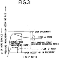
- the relationship between the slip ratio of each wheel with respect to the road surface and a friction coefficient ( ⁇ ) relative to the direction of rotation of each wheel is normally represented as shown in FIG. 1.
- the slip ratio vs. friction coefficient characteristic varies depending on the state of the road surface due to rain, snow or sand or the like.
- the ⁇ value shows the peak in the slip ratio range of 10% to 20%. Therefore, the braking control can be carried out by causing the slip ratio to converge to a range in the vicinity of the slip ratio range of 10% to 20%.
- both a lock speed and a return or reset speed of each wheel with respect to the caliper pressure also vary greatly depending on ⁇ of the road surface.
- the lock speed is slow and the reset speed is fast.
- the reset speed is slow and the lock speed is fast (see FIG. 3).
- the braking control be carried out by estimating ⁇ from an actual vehicle deceleration and a wheel velocity or the like.
- the value of ⁇ tends to vary greatly due to a variation in the state of braking of a front wheel and/or a rear wheel, for example.
- the caliper pressure is directly measured to more accurately estimate ⁇ .
- an expensive and heavy hydraulic-pressure sensor is required, which will cause problems from the standpoint of the manufacturing cost and the weight. Therefore, this type of hydraulic-pressure sensor has not been conventionally used.
- the present invention provides a method of controlling brakes, comprising steps of detecting the position of an expander piston constituting an antilocking modulator, detecting the torque of a rotative drive source for driving the expander piston, computing a braking force for each of the brakes from the detected position of the expander piston and the detected torque of the rotative drive source at the detected position, estimating friction coefficients of a road surface from the computed braking force, and carrying out the optimum braking by estimating a target slip ratio from the estimated friction coefficients.
- a crank angle of a crank pin held in engagement with the expander piston is detected as the step of detecting the position of the expander piston
- a terminal current value of a d.c. motor is detected as the step of detecting the torque of the d.c. motor serving as the rotative drive source
- caliper pressure is computed as a driving force for each of the brakes from the crank angle and the terminal current value to thereby perform the optimum braking.
- the present invention provides a method of controlling brakes, comprising steps of detecting the position of an expander piston constituting an antilocking modulator, detecting the torque of a rotative drive source for driving the expander piston, computing a braking force for each of the brakes from the detected position of the expander piston and the detected torque of the rotative drive source at the detected position, estimating friction coefficients of a road surface from the computed braking force, and carrying out the optimum braking by estimating a pressure increasing and reducing rate from the estimated friction coefficients.
- the present invention provides a method of controlling brakes, comprising steps of detecting the position of an expander piston constituting an antilocking modulator, detecting the torque of a rotative drive source for driving the expander piston, computing a braking force for each of the brakes from the detected position of the expander piston and the detected torque of the rotative drive source at the detected position, estimating friction coefficients of a road surface from the computed braking force, and carrying out the optimum braking by estimating a target slip ratio and a pressure increasing and reducing rate from the estimated friction coefficients.
- the present invention provides a method of controlling brakes, comprising steps of determining a braking force for each of the brakes at the time that a wheel acceleration/deceleration has reached about zero, computing a friction coefficients of a road surface from the determined braking force, averaging the present friction coefficient, the previous friction coefficient and friction coefficients prior to the previous friction coefficient when a slip ratio determined at the time that the wheel acceleration/deceleration is substantially zero is converging to the previously-determined slip ratio, and stopping a process for averaging the present friction coefficient, the previous friction coefficient and the friction coefficients so as to start a process for averaging new friction coefficients including the present friction coefficient when the slip ratio determined at the time that the acceleration/deceleration is substantially zero is diverging from the previously-determined slip ratio.
- step of computing the friction coefficients is executed for every wheel and the step of weighting and averaging the computed friction coefficients is executed in accordance with the number of computations of the friction coefficients for every wheels.
- the step of computing the friction coefficients is executed for every wheel of a four-wheel vehicle, the step of weighting and averaging the friction coefficients is executed for every right front and rear wheel and left front and rear wheel, and the friction coefficients of the right front and rear wheels and the friction coefficients of the left front and rear wheels are weighted and averaged when the differences between the former respective friction coefficients and the latter respective friction coefficients fall within a predetermined range.
- the present invention provides a system for controlling brakes, comprising means for detecting the position of an expander piston constituting an antilocking modulator, means for detecting the torque of a rotative drive source for driving the expander piston, means for computing a braking force for each of the brakes from the detected position of the expander piston and the detected torque of the rotative drive source at the detected position, and means for estimating friction coefficients of a road surface from the computed braking force and estimating a target slip ratio from the estimated friction coefficients.
- the present invention provides a system for controlling brakes, comprising means for detecting the position of an expander piston constituting an antilocking modulator, means for detecting the torque of a rotative drive source for driving the expander piston, means for computing a braking force for each of the brakes from the detected position of the expander piston and the detected torque of the rotative drive source at the detected position, and means for estimating friction coefficients of a road surface from the computed braking force and estimating a pressure increasing and reducing rate from the estimated friction coefficients.
- the present invention provides a system for controlling brakes, comprising means for detecting the position of an expander piston constituting an antilocking modulator, means for detecting the torque of a rotative drive source for driving the expander piston, means for computing a braking force for each of the brakes from the detected position of the expander piston and the detected torque of the rotative drive source at the detected position, and means for estimating friction coefficients of a road surface from the computed braking force and estimating a target slip ratio and a pressure increasing and reducing rate from the estimated friction coefficients.
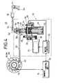
- FIG. 5 is a schematic exterior view showing a motorcycle in which a system for controlling brakes according to a first embodiment of the present invention is incorporated.
- reference numeral 10 indicates the motorcycle.
- the motorcycle 10 comprises a main body 12, a handle 14, a front wheel 16 and a rear wheel 18.
- the brake control system 20 is disposed in the motorcycle 10. As shown in FIG. 4, the brake control system 20 has an antilocking modulator 22. A pinion 26 is rotatably mounted to a d.c. motor (rotative drive source) 24 of the modulator 22 and maintained in meshing engagement with a gear 28. The gear 28 is supported by a crank shaft 30 to which one end of a crank pin 34 is eccentrically coupled via a crank arm 32. A potentiometer 38 serving as a means for detecting the position of an expander piston (to be described later) is attached to the other end of the crank pin 34 via another crank arm 36.
- a cam bearing 40 is rotatably mounted on the crank pin 34.
- the lower end of the cam bearing 40 is always pressed toward the upper limit position under the action of return springs 44 held in a spring holder 42.
- the expander piston 46 is brought into abutment against the upper end of the cam bearing 40 and displaced in upward and downward directions in response to an up-and-down movement of the cam bearing 40 so as to open and close a cup valve 48.
- a cup valve holder 50 having the cup valve 48 incorporated therein is disposed in the upper part of the expander piston 46.
- a master cylinder 56 is coupled via a passage 54 to an input port 52 of the cut valve holder 50.
- a wheel braking caliper cylinder 62 is coupled via a passage 60 to an output port 58 of the cup valve holder 50.
- the master cylinder 56 and the caliper cylinder 62 are interconnected with each other via the passage 54, the modulator 22 and the passage 60. This path is filled with oil for the hydraulic pressure.
- the master cylinder 56 is actuated to adjust the hydraulic pressure under the action of a brake lever 64 so as to cause the cut valve 48 to actuate the caliper cylinder 62, thereby applying a braking force to a disk plate 66 disposed in the front wheel 16 and/or the rear wheel 18.
- a motor controller 70 is electrically connected to the potentiometer 38 and the d.c. motor 24.
- the motor controller 70 is activated to supply information about the angular position of the crank pin 34, which has been detected by the potentiometer 38, i.e., information about the position of the expander piston 46 and a terminal current value of the d.c. motor 24 to a control unit 72.
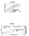
- the control unit 72 has a function for computing caliper pressure (braking forces for brakes) based on the motor torque obtained from the terminal current value of the d.c. motor 24 and the position of the expander piston 46. Further, the control unit 72 also has a memory 74 in which a first table (to be described later) for predicting or estimating a friction coefficient ( ⁇ ) of a road surface based on the initial pressure obtained from the computed caliper pressure and a second table (to be described later) for estimating a target slip ratio and/or a pressure increasing and reducing rate from the estimated friction coefficient ( ⁇ ) have been stored as data.
- a sensor 76 for detecting a wheel speed, which is attached to the disk plate 66, is electrically connected to the control unit 72.
- crank pin 34 Upon normal braking, the crank pin 34 is maintained at a predetermined upper limit position by resilient forces of the return springs 44 to thereby cause the cam bearing 40 mounted on the crank pin 34 to hold the expander piston 46 in a forced-up state.
- the cut valve 48 is forced up by the expander piston 46 so as to cause the input port 52 to communicate with the output port 58.
- the master cylinder 56 When the brake lever 64 is gripped, the master cylinder 56 is actuated in such a manner that brake hydraulic pressure generated by the master cylinder 56 is transmitted to the caliper cylinder 62 through the passage 54, the input port 52, the output port 58 and the passage 60 in that order, thereby applying a braking force to the disk plate 66.
- the motor controller 70 controls the direction and amount of rotation of the d.c. motor 24. Therefore, the pinion 26 mounted on an unillustrated rotatable shaft is rotated to turn both the gear 28 held in meshing engagement with the pinion 26 and the crank arm 32 fixedly mounted to the gear 28 via the crank shaft 30, thereby displacing the crank pin 34 mounted to the crank arm 32 from the upper limit position to the lower limit position.
- the cam bearing 40 is lowered under the displacement action of the crank pin 34, so that the brake hydraulic pressure which acts on the expander piston 46 is added to the torque of the d.c. motor 24. Therefore, the expander piston 46 is pressed against the cam bearing 40 so as to be promptly lowered.
- the cup valve 48 When the expander piston 46 is lowered a predetermined amount, the cup valve 48 is seated to thereby block the communication between the input port 52 and the output port 58. Thus, when the expander piston 46 is further lowered singly, the volume on the output port 58 side increases so as to decrease the hydraulic pressure applied to the caliper cylinder 62, thereby reducing a braking force applied to the front wheel 16, for example.
- the position of the expander piston 46 is detected by the potentiometer 38 as a crank angle in accordance with the displacement of the crank pin 34.
- a value outputted from the potentiometer 38 is introduced into the motor controller 70 as data.
- the motor controller 70 supplies the output value of the potentiometer 38 and the terminal current value of the d.c. motor 24 to the control unit 72.
- the initial pressure (P o ) is computed based on the caliper pressure (PC) and the crank angle at the time of its estimation.
- the initial pressure (P o ) represents the caliper pressure at the moment that the cup valve 48 has been seated.
- ⁇ of the road surface which corresponds to the computed initial pressure (P o ) is estimated based on the first table (see FIG. 6), which has been stored as data in the memory 74 of the control unit 72. Further, the target slip ratio and/or the pressure increasing and reducing rate, which corresponds to the estimated ⁇ , is estimated based on the second table (see FIG. 7) stored as data in the memory 74.
- the control unit 72 outputs a signal for controlling a braking force to the motor controller 70 based on the target slip ratio and/or the pressure increasing and reducing rate in such a manner that the motor controller 70 controls the direction and amount of rotation of the d.c. motor 24, thereby placing the expander piston 46 in a desired position. Consequently, the braking force of the front wheel 16 and/or the rear wheel 18 is controlled.
- the crank angle of the crank pin 34 is detected by the potentiometer 38.
- the terminal current value of the d.c. motor 24 is also detected.
- the caliper pressure (PC) is computed from the detected crank angle and terminal current value.
- the ⁇ and the target slip ratio and/or the pressure increasing and reducing rate are estimated based on the first and second tables after the initial pressure (P o ) has been computed. Therefore, dedicated sensors such as a conventional expensive and heavy hydraulic sensor, etc. can be omitted, thereby making it possible to provide the brake control system 20 which is extremely economical and light in weight.
- the optimum target slip ratio can be estimated based on the estimated ⁇ . That is, the target slip ratio can be set to a low value so as to secure the stability of the vehicle under the low ⁇ road. On the other hand, the target slip ratio can be set to a high value so as to secure a satisfactory deceleration under the high ⁇ road.
- a ⁇ -S curve itself can be computed based on the caliper pressure (PC) computed from the equations (1) through (3), a wheel acceleration/deceleration determined from the sensor 76 and the wheel slip ratio or the like.
- PC caliper pressure
- the first embodiment has shown a case in which the caliper pressure of the caliper cylinder 62 for applying the braking force to the disk plate 66 is computed so as to estimate the ⁇ and the target slip ratio.
- the present embodiment can be applied even to a case where a braking force is applied to a drum brake.
- a brake shoe attached to the drum brake under pressure is used as the caliper cylinder 62.
- the caliper pressure (PC) corresponding to the degree of opening of the brake shoe is computed based on a crank angle and a terminal current value, thereby estimating ⁇ and a target slip ratio based on the computed caliper pressure (PC).
- the above-described embodiment has shown a case in which the front wheel 16 is controlled, as an illustrative example.
- the rear wheel 18 can also be controlled in the same manner as described above.
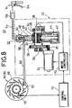
- a method of controlling brakes according to a second embodiment of the present invention will now be described below in connection with a system for carrying out the brake control method.
- the same elements of structure as those employed in the brake control system 20 according to the first embodiment are identified by like reference numerals and their detailed description will therefore be omitted.
- the brake control system 20 is provided with a control unit 72 which has a function for computing caliper pressure (braking forces for brakes) based on the motor torque determined from a terminal current value of a d.c. motor 24 and the position of an expander piston 46 and a function for computing a friction coefficient ( ⁇ ) of a road surface based on the computed caliper pressure.
- a crank pin 34 Upon normal braking, a crank pin 34 is maintained at a predetermined upper limit position by resilient forces of return springs 44 to thereby cause a cam bearing 40 mounted on a crank pin 34 to hold the expander piston 46 in a forced-up state.
- a cup valve 48 is forced up by the expander piston 46 so as to cause an input port 52 to communicate with an output port 58.
- a master cylinder 56 is actuated in such a manner that brake hydraulic pressure generated by the master cylinder 56 is transmitted to a caliper cylinder 62 through a passage 54, the input port 52, the output port 58 and a passage 60 in that order, thereby applying a braking force to a disk plate 66.
- the control unit 72 When the control unit 72 then supplies a drive signal to a motor controller 70 so as to control a desired brake, the motor controller 70 controls the direction and amount of rotation of the d.c. motor 24. Therefore, a pinion 26 mounted on an unillustrated rotatable shaft is rotated to turn both a gear 28 held in meshing engagement with the pinion 26 and a crank arm 32 fixedly mounted to the gear 28 via a crank shaft 30, thereby displacing the crank pin 34 mounted to the crank arm 32 from the upper limit position to the lower limit position.
- the cam bearing 40 is lowered under the displacement action of the crank pin 34, so that the brake hydraulic pressure which acts on the expander piston 46 is added to the torque of the d.c. motor 24. Therefore, the expander piston 46 is pressed against the cam bearing 40 so as to be promptly lowered.
- the cup valve 48 When the expander piston 46 is lowered a predetermined amount, the cup valve 48 is seated to thereby block the communication between the input port 52 and the output port 58. Thus, when the expander piston 46 is further lowered singly, the volume on the output port 58 side increases so as to decrease the hydraulic pressure applied to the caliper cylinder 62, thereby reducing a braking force applied to a front wheel 16, for example.
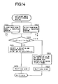
- Step S1 a process for computing a friction coefficient ( ⁇ ) of a road surface is carried out in accordance with a flowchart shown in FIG. 9.
- a description will be first made of the front wheel 16. If it is detected by a sensor 76 attached to the disk plate 66 of the front wheel 16 that an acceleration/deceleration ⁇ of the front wheel 16 has reached about zero (Step S1), then a slip ratio ( ⁇ ) is computed. It is then determined whether the front wheel 16 has been brought into an accelerated state or a decelerated state (Step S2). The routine procedure proceeds to Step S3 or S4 based on the result of determination. If the acceleration/deceleration ( ⁇ ) of the front wheel 16 has reached about zero from the decelerated state (see FR1 in FIG.
- Step S5 the speed of the front wheel 16 is reduced as compared with a vehicle speed or velocity V, thereby increasing the slip ratio ( ⁇ ). Then, the slip ratio ( ⁇ ) is compared with the preset maximum slip ratio ( ⁇ MAX). If ⁇ MAX (i.e., if the answer is determined to be YES in Step S3), then ⁇ is set to ⁇ MAX (Step S5).
- ⁇ (K ⁇ P + I ⁇ )/WH
- K brake resistive force per unit hydraulic pressure
- P brake hydraulic pressure (caliper pressure)
- I wheel inertial gravity
- ⁇ wheel acceleration/deceleration
- WH wheel sharing load
- the brake hydraulic pressure P may be directly measured by a hydraulic-pressure gage.
- the brake hydraulic pressure P can be determined by computation as will be described later. That is, the position of the expander piston 46 is detected as a crank angle by a potentiometer 38 in accordance with the displacement of the crank pin 34. A value outputted from the potentiometer 38 is introduced into the motor controller 70 as data. Afterwards, the motor controller 70 supplies the output value of the potentiometer 38 and the terminal current value of the d.c. motor 24 to the control unit 72. In the control unit 102, the motor torque (TM) of the d.c.
- TM KT ⁇ (IM - IO)
- TM motor torque
- IM motor current
- JM motor inertial mass
- ⁇ crank angular acceleration
- TF friction torque
- e eccentric amount of crank
- KT motor torque constant IO: motor non-load current
- Z reduction ratio
- JC crank inertial mass
- TS B/USPG torque
- D diameter of expander piston ⁇ c : crank angle
- Step S6 After the friction coefficient ( ⁇ ) has been computed (Step S6), the routine procedure is returned to Step S1 via Steps S7 and S8 when the routine procedure for computing the friction coefficient is executed as the first time. If, on the other hand, this routine procedure is executed as the second time and after, then a process for averaging computed friction coefficients ( ⁇ ) is carried out (Step S9).
- Step S2 If, on the other hand, it is determined in Step S2 that the acceleration/deceleration ( ⁇ ) of the front wheel 16 has reached about zero from the accelerated state (see NO in Step S2 and FR2 in FIG. 10), then the speed of the front wheel 16 comes as close as possible to the vehicle velocity V, thereby reducing the slip ratio ( ⁇ ). Then, the slip ratio ( ⁇ ) is compared with the preset minimum slip ratio ( ⁇ MIN). If ⁇ MIN (i.e., if the answer is determined to be YES in Step S4), then this ⁇ is set to ⁇ MIN (Step S10).
- ⁇ MIN i.e., if the answer is determined to be YES in Step S4
- a process for averaging the computed friction coefficients ( ⁇ ) is carried out to set n to be greater than 1 (i.e., n>1) (Steps S6 through S9).
- slip ratios ( ⁇ ) at the time that the acceleration/deceleration ( ⁇ ) of the front wheel 16 has reached about zero are computed. Afterwards, the slip ratios ( ⁇ ) thus determined are successively compared with the minimum slip ratio. If it is determined that the slip ratios ( ⁇ ) thus determined have converged to the previously determined slip ratio ( ⁇ ), then a process for averaging the friction coefficients ( ⁇ ) at the respective points (FR1 through FRn) is carried out (see the computed ⁇ in FIG. 10).
- Step S3 When the state of the road surface is changed from a dry asphalt road (high ⁇ road) to a frozen road (low ⁇ road) as shown in FIG. 11, the slip ratio ( ⁇ ) at the FR5 point becomes larger than that at the FR3 point. Therefore, the answer is determined to be NO in Step S3.
- the friction coefficients ( ⁇ ) computed at the respective points (FR1 through FRn) are averaged in the second embodiment. It is therefore possible to obtain values which are as close as possible to actual friction coefficients ( ⁇ ).
- highly accurate and most suitable brake control can be carried out by adjusting the caliper pressure of the front wheel 16 based on the computed ⁇ . Further, if it is determined that the state of the road surface has been changed after the respective slip ratios ( ⁇ ) have been successively compared with the reference slip ratio, then the averaging process of the friction coefficients ( ⁇ ) is stopped so as to start a ⁇ re-averaging process.
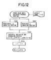
- the four-wheel vehicle 190 is provided with front wheels 192R, 192L and rear wheels 194R, 194L.
- ⁇ of the front wheels 192R, 192L and ⁇ of the rear wheels 194R, 194L are respectively averaged in accordance with the ⁇ computing routine shown in FIG.9.
- the averaged ⁇ of the front wheels 192R, 192L and the averaged ⁇ of the rear wheels 194R, 194L are weighted and averaged in accordance with a front-rear wheel weighted mean or average routine to thereby compute ⁇ R and ⁇ L (Steps S201 and S202).
- Step S203 It is determined in Step S203 whether or not the ⁇ R is approximate to the ⁇ L, that is, the left and right road surfaces belong to either the high ⁇ road or the low ⁇ road. If it is determined that the ⁇ R is approximate to the ⁇ L (i.e., if the answer is determined to be No in Step S203), then the ⁇ R and ⁇ L are subjected to the weighted average process so as to compute ⁇ of the road surfaces (Steps S204 and S205).
- the ⁇ R and ⁇ L are not weighted and averaged and processes for controlling braking of both the front wheels 192R, 192L and the rear wheels 194R, 194L are independently carried out based on the ⁇ R and ⁇ L (see Steps S206 and S207 and a split road between A and B in FIG. 15). In the B point in FIG. 15, the ⁇ R approximates to the ⁇ L again.
- the ⁇ R and ⁇ L are subjected to the weighted average process.
- a judgment to be made as to whether or not the'weighted means process of the ⁇ R and ⁇ L should be carried out, can be variously changed by setting the value of ⁇ 0.
- a braking force for each of the brakes is computed based on the position of an expander position of an antilocking modulator and the torque of a rotative drive source for driving the expander piston.
- a friction coefficient of a road surface is estimated from the computed braking force.
- a target slip ratio and/or a pressure increasing and reducing rate is estimated from the estimated friction coefficient to thereby carry out the optimum braking. Therefore, the optimum target slip ratio and/or pressure increasing and reducing rate can be estimated in association with high and low ⁇ roads, thereby making it possible to provide satisfactory braking.
- the braking force for each of the brakes at the time that a wheel acceleration/deceleration has reached about zero is measured or computed and the friction coefficient of the road surface is computed based on the computed braking force. Therefore, such a computing process can be carried out with ease and in a short time without taking into consideration the wheel acceleration/deceleration. It is also possible to obtain a more accurate friction coefficient by averaging respective friction coefficients, thereby making it possible to control the brakes with high accuracy.
- the friction coefficient can be computed with high accuracy. It is thus possible to immediately meet any variation in the state of the road surface and carry out the most suitable brake control.
Landscapes
- Engineering & Computer Science (AREA)
- Transportation (AREA)
- Mechanical Engineering (AREA)
- Physics & Mathematics (AREA)
- Fluid Mechanics (AREA)
- Microelectronics & Electronic Packaging (AREA)
- Regulating Braking Force (AREA)
Priority Applications (1)
| Application Number | Priority Date | Filing Date | Title |
|---|---|---|---|
| EP95101386A EP0656291B1 (fr) | 1991-09-17 | 1992-09-15 | Méthode pour commander les freins |
Applications Claiming Priority (4)
| Application Number | Priority Date | Filing Date | Title |
|---|---|---|---|
| JP23653791A JP2901396B2 (ja) | 1991-09-17 | 1991-09-17 | ブレーキ制御方法および装置 |
| JP236537/91 | 1991-09-17 | ||
| JP241980/91 | 1991-09-20 | ||
| JP24198091A JP2855006B2 (ja) | 1991-09-20 | 1991-09-20 | ブレーキ制御方法 |
Related Child Applications (2)
| Application Number | Title | Priority Date | Filing Date |
|---|---|---|---|
| EP95101386.1 Division-Into | 1992-09-15 | ||
| EP95101386A Division EP0656291B1 (fr) | 1991-09-17 | 1992-09-15 | Méthode pour commander les freins |
Publications (3)
| Publication Number | Publication Date |
|---|---|
| EP0533436A2 true EP0533436A2 (fr) | 1993-03-24 |
| EP0533436A3 EP0533436A3 (en) | 1993-09-15 |
| EP0533436B1 EP0533436B1 (fr) | 1996-08-21 |
Family
ID=26532722
Family Applications (2)
| Application Number | Title | Priority Date | Filing Date |
|---|---|---|---|
| EP95101386A Expired - Lifetime EP0656291B1 (fr) | 1991-09-17 | 1992-09-15 | Méthode pour commander les freins |
| EP92308389A Expired - Lifetime EP0533436B1 (fr) | 1991-09-17 | 1992-09-15 | Méthode et système pour commander les freins |
Family Applications Before (1)
| Application Number | Title | Priority Date | Filing Date |
|---|---|---|---|
| EP95101386A Expired - Lifetime EP0656291B1 (fr) | 1991-09-17 | 1992-09-15 | Méthode pour commander les freins |
Country Status (3)
| Country | Link |
|---|---|
| US (1) | US5249848A (fr) |
| EP (2) | EP0656291B1 (fr) |
| DE (2) | DE69225147T2 (fr) |
Cited By (7)
| Publication number | Priority date | Publication date | Assignee | Title |
|---|---|---|---|---|
| EP0575991A2 (fr) * | 1992-06-24 | 1993-12-29 | Honda Giken Kogyo Kabushiki Kaisha | Système de commande de frein |
| EP0575944A1 (fr) * | 1992-06-24 | 1993-12-29 | Honda Giken Kogyo Kabushiki Kaisha | Appareil pour calculer le coefficient de friction du revêtement de la route |
| EP0624498A2 (fr) * | 1993-05-14 | 1994-11-17 | Suzuki Kabushiki Kaisha | Système de freinage anti-blocage pour moto |
| GB2334767A (en) * | 1997-10-24 | 1999-09-01 | Siemens Ag | Electrically actuated braking system for a motor vehicle |
| EP1568561A1 (fr) * | 2004-02-24 | 2005-08-31 | HONDA MOTOR CO., Ltd. | Dispositif de freinage pour motocyclette |
| EP1671864A1 (fr) * | 2004-12-20 | 2006-06-21 | HONDA MOTOR CO., Ltd. | Système de freinage pour moto |
| CN100436212C (zh) * | 2004-12-20 | 2008-11-26 | 本田技研工业株式会社 | 摩托车的制动装置 |
Families Citing this family (18)
| Publication number | Priority date | Publication date | Assignee | Title |
|---|---|---|---|---|
| CA2080112C (fr) * | 1991-10-08 | 1998-07-28 | Osamu Suzuki | Methode pour estimer la velocite d'un vehicule et methode et systeme de commande de frein |
| DE4210576C1 (fr) * | 1992-03-31 | 1993-08-05 | Temic Telefunken Microelectronic Gmbh, 7100 Heilbronn, De | |
| JPH06293254A (ja) * | 1993-04-07 | 1994-10-21 | Sumitomo Electric Ind Ltd | アンチロックブレーキ制御装置 |
| US5385394A (en) * | 1993-05-11 | 1995-01-31 | General Motors Corporation | Antilock brake system with controlled pressure augmentation |
| JP3599120B2 (ja) * | 1994-09-30 | 2004-12-08 | 本田技研工業株式会社 | 液圧制御装置 |
| US5558409A (en) * | 1994-12-14 | 1996-09-24 | General Motors Corporation | Electrohydraulic braking system |
| JP3456835B2 (ja) * | 1996-06-10 | 2003-10-14 | 日信工業株式会社 | 車両のアンチロックブレーキ制御装置 |
| US6293632B1 (en) | 1999-06-11 | 2001-09-25 | John F. Grote | Vehicular brake-by-wire system |
| JP2001278024A (ja) * | 2000-03-29 | 2001-10-10 | Honda Motor Co Ltd | アンチロックブレーキシステムの制御装置 |
| JP3992174B2 (ja) * | 2000-03-29 | 2007-10-17 | 本田技研工業株式会社 | アンチロックブレーキシステムの制御装置 |
| JP3824308B2 (ja) * | 2001-12-27 | 2006-09-20 | ボッシュ株式会社 | リファレンス速度演算方法、アンチロック・ブレーキ・システム、アンチロック・ブレーキ制御プログラム |
| JP4361385B2 (ja) * | 2004-01-30 | 2009-11-11 | 本田技研工業株式会社 | 自動二輪車のブレーキ装置 |
| EP1674360B1 (fr) * | 2004-12-24 | 2012-01-18 | Honda Motor Co., Ltd. | Dispositif de freinage pour véhicules et méthode de commande s'y rapportant |
| JP4649352B2 (ja) * | 2005-03-17 | 2011-03-09 | 日信工業株式会社 | 車両用ブレーキ制御装置およびブレーキ制御方法 |
| EP1839977B1 (fr) * | 2006-03-31 | 2016-05-04 | Honda Motor Co., Ltd. | Système de frein pour motocyclette |
| JP4563987B2 (ja) * | 2006-11-29 | 2010-10-20 | 本田技研工業株式会社 | 車両の車輪制動制御装置 |
| US8237431B2 (en) * | 2007-07-05 | 2012-08-07 | Terry Fruehling | Wheel speed sensor |
| DE102011077313A1 (de) * | 2011-06-09 | 2012-12-13 | Continental Teves Ag & Co. Ohg | Verfahren zum Betreiben einer Bremsanlage sowie Bremsanlage |
Citations (7)
| Publication number | Priority date | Publication date | Assignee | Title |
|---|---|---|---|---|
| EP0200413A2 (fr) * | 1985-05-01 | 1986-11-05 | Automotive Products Public Limited Company | Dispositifs de freinage antiblocage de véhicule |
| EP0219023A2 (fr) * | 1985-10-08 | 1987-04-22 | Robert Bosch Gmbh | Système pour la régulation de la pression des freins |
| DE3717531A1 (de) * | 1986-05-30 | 1987-12-03 | Tokico Ltd | Blockierschutzeinrichtung |
| EP0298617A2 (fr) * | 1987-07-09 | 1989-01-11 | General Motors Corporation | Dispositif de commande des freins anti-blocage actionné par moteur-couple à courant continu |
| EP0392686A2 (fr) * | 1989-04-13 | 1990-10-17 | General Motors Corporation | Dispositif et méthode de commande antiblocage |
| EP0395225A2 (fr) * | 1989-04-24 | 1990-10-31 | General Motors Corporation | Modulator de pression pour systèmes de freinage à antiblocage |
| WO1992007741A1 (fr) * | 1990-11-02 | 1992-05-14 | Robert Bosch Gmbh | Systeme d'antiblocage des roues |
Family Cites Families (3)
| Publication number | Priority date | Publication date | Assignee | Title |
|---|---|---|---|---|
| DE3530280A1 (de) * | 1985-08-24 | 1987-02-26 | Kugelfischer G Schaefer & Co | Verfahren zum blockiergeschuetzten abbremsen eines kraftfahrzeuges |
| US4997237A (en) * | 1989-09-22 | 1991-03-05 | General Motors Corporation | Bi-modal DC motor control for a motor driven anti-lock brake system |
| JPH04146862A (ja) * | 1990-10-09 | 1992-05-20 | Honda Motor Co Ltd | 制動液圧制御装置 |
-
1992
- 1992-09-15 DE DE69225147T patent/DE69225147T2/de not_active Expired - Fee Related
- 1992-09-15 DE DE69212935T patent/DE69212935T2/de not_active Expired - Fee Related
- 1992-09-15 EP EP95101386A patent/EP0656291B1/fr not_active Expired - Lifetime
- 1992-09-15 EP EP92308389A patent/EP0533436B1/fr not_active Expired - Lifetime
- 1992-09-16 US US07/945,382 patent/US5249848A/en not_active Expired - Fee Related
Patent Citations (7)
| Publication number | Priority date | Publication date | Assignee | Title |
|---|---|---|---|---|
| EP0200413A2 (fr) * | 1985-05-01 | 1986-11-05 | Automotive Products Public Limited Company | Dispositifs de freinage antiblocage de véhicule |
| EP0219023A2 (fr) * | 1985-10-08 | 1987-04-22 | Robert Bosch Gmbh | Système pour la régulation de la pression des freins |
| DE3717531A1 (de) * | 1986-05-30 | 1987-12-03 | Tokico Ltd | Blockierschutzeinrichtung |
| EP0298617A2 (fr) * | 1987-07-09 | 1989-01-11 | General Motors Corporation | Dispositif de commande des freins anti-blocage actionné par moteur-couple à courant continu |
| EP0392686A2 (fr) * | 1989-04-13 | 1990-10-17 | General Motors Corporation | Dispositif et méthode de commande antiblocage |
| EP0395225A2 (fr) * | 1989-04-24 | 1990-10-31 | General Motors Corporation | Modulator de pression pour systèmes de freinage à antiblocage |
| WO1992007741A1 (fr) * | 1990-11-02 | 1992-05-14 | Robert Bosch Gmbh | Systeme d'antiblocage des roues |
Cited By (13)
| Publication number | Priority date | Publication date | Assignee | Title |
|---|---|---|---|---|
| US5385393A (en) * | 1992-06-24 | 1995-01-31 | Honda Giken Kogyo Kabushiki Kaisha | Device for calculating coefficient of friction of road surface |
| EP0575944A1 (fr) * | 1992-06-24 | 1993-12-29 | Honda Giken Kogyo Kabushiki Kaisha | Appareil pour calculer le coefficient de friction du revêtement de la route |
| EP0575991A3 (en) * | 1992-06-24 | 1997-06-11 | Honda Motor Co Ltd | Brake control system |
| EP0575991A2 (fr) * | 1992-06-24 | 1993-12-29 | Honda Giken Kogyo Kabushiki Kaisha | Système de commande de frein |
| EP0624498A3 (fr) * | 1993-05-14 | 1995-01-25 | Suzuki Co Ltd | Système de freinage anti-blocage pour moto. |
| US5419625A (en) * | 1993-05-14 | 1995-05-30 | Suzuki Kabushiki Kaisha | Antiskid braking device for motorcycle |
| EP0624498A2 (fr) * | 1993-05-14 | 1994-11-17 | Suzuki Kabushiki Kaisha | Système de freinage anti-blocage pour moto |
| GB2334767A (en) * | 1997-10-24 | 1999-09-01 | Siemens Ag | Electrically actuated braking system for a motor vehicle |
| GB2334767B (en) * | 1997-10-24 | 2001-08-08 | Siemens Ag | Method for electrically actuated braking of a motor vehicle and electrically actuated brake system |
| EP1568561A1 (fr) * | 2004-02-24 | 2005-08-31 | HONDA MOTOR CO., Ltd. | Dispositif de freinage pour motocyclette |
| EP1671864A1 (fr) * | 2004-12-20 | 2006-06-21 | HONDA MOTOR CO., Ltd. | Système de freinage pour moto |
| CN100436212C (zh) * | 2004-12-20 | 2008-11-26 | 本田技研工业株式会社 | 摩托车的制动装置 |
| US7891746B2 (en) | 2004-12-20 | 2011-02-22 | Honda Motor Co., Ltd. | Braking device for motorcycle |
Also Published As
| Publication number | Publication date |
|---|---|
| DE69225147D1 (de) | 1998-05-20 |
| EP0533436B1 (fr) | 1996-08-21 |
| US5249848A (en) | 1993-10-05 |
| EP0533436A3 (en) | 1993-09-15 |
| EP0656291B1 (fr) | 1998-04-15 |
| DE69212935T2 (de) | 1997-01-16 |
| EP0656291A1 (fr) | 1995-06-07 |
| DE69225147T2 (de) | 1998-08-06 |
| DE69212935D1 (de) | 1996-09-26 |
Similar Documents
| Publication | Publication Date | Title |
|---|---|---|
| EP0656291B1 (fr) | Méthode pour commander les freins | |
| EP0678431B1 (fr) | Méthode pour le contrôle des freins | |
| US5257856A (en) | Method of and system for controlling brakes | |
| US6236926B1 (en) | Vehicle behavior control device | |
| EP0927670B1 (fr) | Système,méthode et appareil de commande pour commander le freinage d'une roue de véhicule | |
| US7059687B2 (en) | Braking force distribution control device | |
| EP0537995B1 (fr) | Méthode et système pour commander des freins | |
| JPH0620880B2 (ja) | 車両のアンチロツク制御方法 | |
| EP0581894B1 (fr) | Freinage par regulation de la deceleration | |
| JP2901396B2 (ja) | ブレーキ制御方法および装置 | |
| JP2855006B2 (ja) | ブレーキ制御方法 | |
| KR970010065B1 (ko) | 차량용 앤티록브레이크시스템의 브레이크압력 제어방법 | |
| JP2696859B2 (ja) | 車両用制御装置 | |
| JP2001287635A (ja) | 制動力配分制御装置 | |
| JP3582600B2 (ja) | ブレーキ制御装置 | |
| JP2623565B2 (ja) | アンチスキツド制御装置 | |
| JP3040018B2 (ja) | ブレーキ制御方法 | |
| JP2908913B2 (ja) | アンチロックブレーキ用モジュレータのクランク角制御装置 | |
| JPH0624911B2 (ja) | 車両のアンチロツク制御方法 | |
| JPH04328063A (ja) | 路面の摩擦係数の推定装置 | |
| JPH1134846A (ja) | Abs装置 | |
| JPH07156781A (ja) | アンチスキッド制御装置 | |
| JPH07106698B2 (ja) | アンチロックブレーキ装置付き車両における車輪空転検知方法 | |
| JPH06135310A (ja) | ブレーキ制御方法 | |
| JPH0723088B2 (ja) | 自走車両の駆動力制御装置 |
Legal Events
| Date | Code | Title | Description |
|---|---|---|---|
| PUAI | Public reference made under article 153(3) epc to a published international application that has entered the european phase |
Free format text: ORIGINAL CODE: 0009012 |
|
| AK | Designated contracting states |
Kind code of ref document: A2 Designated state(s): DE FR |
|
| PUAL | Search report despatched |
Free format text: ORIGINAL CODE: 0009013 |
|
| AK | Designated contracting states |
Kind code of ref document: A3 Designated state(s): DE FR |
|
| 17P | Request for examination filed |
Effective date: 19940203 |
|
| 17Q | First examination report despatched |
Effective date: 19941128 |
|
| GRAG | Despatch of communication of intention to grant |
Free format text: ORIGINAL CODE: EPIDOS AGRA |
|
| GRAH | Despatch of communication of intention to grant a patent |
Free format text: ORIGINAL CODE: EPIDOS IGRA |
|
| GRAH | Despatch of communication of intention to grant a patent |
Free format text: ORIGINAL CODE: EPIDOS IGRA |
|
| GRAA | (expected) grant |
Free format text: ORIGINAL CODE: 0009210 |
|
| DX | Miscellaneous (deleted) | ||
| AK | Designated contracting states |
Kind code of ref document: B1 Designated state(s): DE FR |
|
| REF | Corresponds to: |
Ref document number: 69212935 Country of ref document: DE Date of ref document: 19960926 |
|
| ET | Fr: translation filed | ||
| PLBE | No opposition filed within time limit |
Free format text: ORIGINAL CODE: 0009261 |
|
| STAA | Information on the status of an ep patent application or granted ep patent |
Free format text: STATUS: NO OPPOSITION FILED WITHIN TIME LIMIT |
|
| 26N | No opposition filed | ||
| PGFP | Annual fee paid to national office [announced via postgrant information from national office to epo] |
Ref country code: FR Payment date: 20020910 Year of fee payment: 11 |
|
| PGFP | Annual fee paid to national office [announced via postgrant information from national office to epo] |
Ref country code: DE Payment date: 20020918 Year of fee payment: 11 |
|
| PG25 | Lapsed in a contracting state [announced via postgrant information from national office to epo] |
Ref country code: DE Free format text: LAPSE BECAUSE OF NON-PAYMENT OF DUE FEES Effective date: 20040401 |
|
| PG25 | Lapsed in a contracting state [announced via postgrant information from national office to epo] |
Ref country code: FR Free format text: LAPSE BECAUSE OF NON-PAYMENT OF DUE FEES Effective date: 20040528 |
|
| REG | Reference to a national code |
Ref country code: FR Ref legal event code: ST |