EP0532860B1 - Rolleneinrichtung für eine einer Backenschiene zugeordneten Zunge einer Weiche - Google Patents
Rolleneinrichtung für eine einer Backenschiene zugeordneten Zunge einer Weiche Download PDFInfo
- Publication number
- EP0532860B1 EP0532860B1 EP92112528A EP92112528A EP0532860B1 EP 0532860 B1 EP0532860 B1 EP 0532860B1 EP 92112528 A EP92112528 A EP 92112528A EP 92112528 A EP92112528 A EP 92112528A EP 0532860 B1 EP0532860 B1 EP 0532860B1
- Authority
- EP
- European Patent Office
- Prior art keywords
- spring
- roller
- tongue
- support
- assembly according
- Prior art date
- Legal status (The legal status is an assumption and is not a legal conclusion. Google has not performed a legal analysis and makes no representation as to the accuracy of the status listed.)
- Expired - Lifetime
Links
- 238000005096 rolling process Methods 0.000 title 1
- 238000013016 damping Methods 0.000 claims description 16
- 229920001971 elastomer Polymers 0.000 claims description 3
- 239000000806 elastomer Substances 0.000 claims description 3
- 230000004308 accommodation Effects 0.000 abstract 2
- 241001669679 Eleotris Species 0.000 abstract 1
- 230000004075 alteration Effects 0.000 abstract 1
- 238000006073 displacement reaction Methods 0.000 abstract 1
- 210000002105 tongue Anatomy 0.000 description 30
- 239000000725 suspension Substances 0.000 description 6
- 238000010586 diagram Methods 0.000 description 3
- 230000000694 effects Effects 0.000 description 2
- 230000006378 damage Effects 0.000 description 1
- 230000007423 decrease Effects 0.000 description 1
- 230000000763 evoking effect Effects 0.000 description 1
- 239000002184 metal Substances 0.000 description 1
- 230000000750 progressive effect Effects 0.000 description 1
- 210000005181 root of the tongue Anatomy 0.000 description 1
- 230000035939 shock Effects 0.000 description 1
- 210000005182 tip of the tongue Anatomy 0.000 description 1
Images

Classifications
-
- E—FIXED CONSTRUCTIONS
- E01—CONSTRUCTION OF ROADS, RAILWAYS, OR BRIDGES
- E01B—PERMANENT WAY; PERMANENT-WAY TOOLS; MACHINES FOR MAKING RAILWAYS OF ALL KINDS
- E01B7/00—Switches; Crossings
- E01B7/02—Tongues; Associated constructions
-
- E—FIXED CONSTRUCTIONS
- E01—CONSTRUCTION OF ROADS, RAILWAYS, OR BRIDGES
- E01B—PERMANENT WAY; PERMANENT-WAY TOOLS; MACHINES FOR MAKING RAILWAYS OF ALL KINDS
- E01B2202/00—Characteristics of moving parts of rail systems, e.g. switches, special frogs, tongues
- E01B2202/02—Nature of the movement
- E01B2202/027—Including a component perpendicular to the plane of the rails
-
- E—FIXED CONSTRUCTIONS
- E01—CONSTRUCTION OF ROADS, RAILWAYS, OR BRIDGES
- E01B—PERMANENT WAY; PERMANENT-WAY TOOLS; MACHINES FOR MAKING RAILWAYS OF ALL KINDS
- E01B2202/00—Characteristics of moving parts of rail systems, e.g. switches, special frogs, tongues
- E01B2202/04—Nature of the support or bearing
- E01B2202/044—Rolling
- E01B2202/046—Rolling with rolls on fixed part
-
- E—FIXED CONSTRUCTIONS
- E01—CONSTRUCTION OF ROADS, RAILWAYS, OR BRIDGES
- E01B—PERMANENT WAY; PERMANENT-WAY TOOLS; MACHINES FOR MAKING RAILWAYS OF ALL KINDS
- E01B2202/00—Characteristics of moving parts of rail systems, e.g. switches, special frogs, tongues
- E01B2202/04—Nature of the support or bearing
- E01B2202/044—Rolling
- E01B2202/048—Rolling with rolls on moving part
Definitions
- the invention relates to a roller device for a tongue of a switch associated with a cheek rail that originates indirectly or directly from a support such as a threshold, and comprises at least one roller element that is intended to support the tongue and that is indirectly or directly spring-supported.
- rollers To reduce the friction when adjusting switch tongues, these can be stored on rollers. It is known that two roller elements start from a holder, on which a tongue to be opened is supported in sections. Bracket and roller elements are at a fixed distance from the stock rail to be arranged on the bracket. Since the distance between the stock rail and the open tongue decreases from the tip of the tongue to the root of the tongue, a large number of different roller devices are required in order to enable support.
- roller bearing for switch tongues.
- the roller bearing used has a purely supporting function.
- the roller itself is mounted in a roller block, which is arranged in a cage of a bearing block. Since the spring does not dampen, there can be knocks between the roller block and the bearing block. This in turn leads to shock loads on the tongue.
- a switch tongue is supported on a roller, which in turn is held by a rod spring assembly.
- a switch tongue according to DE-OS 1 658 366 is supported on rollers extending from a roller block.
- the problem underlying the present invention is to ensure that the switch tongue does not hit a support such as a sliding chair even when vibration is excited.
- roller element is supported on at least two spring elements of different characteristics, that the one spring element has a substantially constant stiffness and the other spring element has a variable stiffness and that the spring elements are mechanically coupled to each other in such a way that at Tongue-loaded roller element, each spring element is elastically deformable.
- the invention is characterized in that the spring elements extend on opposite sides of a carrier element and can be changed in distance via a connecting element such as a screw are adjustable to each other that the damping spring element with the variable stiffness runs on the side of the support element facing away from the tongue, that the spring element with the variable stiffness when the roller element is unloaded is tightened by the connecting element against the support element in such a way that a spring effect is excluded or im is essentially excluded, and that when the roller element is loaded, each of the spring elements has usual additional loading and unloading of the roller element absorbing spring travel lengths.
- a connecting element such as a screw
- the spring elements are, on the one hand, a suspension spring and, on the other hand, a damping spring, at least the latter, but preferably both, being elastomer springs.
- the damping spring has a stiffness that is preferably ten times smaller than that of the suspension spring.
- the damping spring When prestressing the spring elements, i.e. when the roller element is not loaded, the damping spring is set to block or almost to block, in order then to get into a working position (working point) with the roller element loaded by the tongue (working point), which makes it possible for conventional Loading and unloading of the roller element by the tongue acting on this the pre-stress point, that is, the block position is not reached.
- the damping spring provides suspension and thus damping in both directions, so that an effective opening of the tongue on a surface such as a sliding chair is excluded.
- vibration in the tongue itself is reduced quickly evoked.
- the rigidity of the suspension spring determines the working position of the roller elements, that is, the level at which the tongue comes to rest.
- the roller element can start from a receptacle in which the tongue, e.g. can be positively fixed.
- the recording itself can be connected to the stock rail in the usual way, but preferably with the support such as a threshold. The latter measure causes a further decoupling from the stock rail.
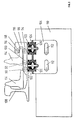
- FIG. 1 and 2 illustrate that, based on the teaching according to the invention, a switch tongue (114) to be mounted or displaced on the roller elements (90), (92) and (94) is damped to such an extent that striking occurs Documents such as sliding chairs are excluded. At the same time, this ensures that the roller elements (90), (92) and (94) do not have any impact-like impacts leading to destruction, a disadvantage which is inherent in the roller elements which can be found in the prior art.
- roller elements (90), (92) and (94) which can be seen in FIG. 2 and a further roller element (96) are based on a receptacle (98) which, in side view, has a shape of a lying Us with different leg lengths.
- the longer leg (100) faces a holder (106).
- the receptacle (98) is supported on spring devices (102) and (104), which in turn are fastened on the holder (106), which in the exemplary embodiment is based on a threshold (110).
- the holder (106) can be moved in the direction of or from a stock rail (108).
- side legs of the holder (106) have elongated holes (112) which can be penetrated by fastening elements such as screws, which connect the holder (106) to the threshold (110).
- the receptacle (98) itself preferably consists of two cheeks having the U-shape, in which the roller elements (90), (92), (94) and (96) are mounted and which are connected, for example, by a flat section which is on the spring devices (102) and (104) is attached.
- FIG. 2 shows a switch tongue (114) to be assigned to the stock rail (108) on the one hand in the adjacent (strong solid line) and on the other hand in the remote position (weak solid line).
- a section of the switch tongue foot (116) rests between the rollers (94) and (96), that is to say between the short leg (118) and the long leg (100) of the U-shaped receptacle (98) of the roller elements in side view (90), (92), (94) and (96).
- This measure has the effect that the switch tongue (114) is also virtually locked in the remote position in order to prevent it from striking.
- Each spring device (102) or (104) consists of an upper and a lower plate element (124) and (126), preferably made of metal, and a support plate (128) running between them, which starts from the holder (106).
- Spring elements (122) and (120) of different stiffnesses extend between the carrier plate (128) and the upper plate (124) on the one hand and between the carrier plate (128) and the lower plate (126) facing away from the stock rail (108).
- the stiffnesses of the spring elements (120) and (122), which are elastomer springs, which are connected to the plates (124), (126), (128) or to portions, but not specified, starting from them, but vulcanized are shown in the appendix of FIG. 1a.
- the spring elements (120) and (122) are mechanically coupled by a connecting element. This passes through the spring devices (120) and (104) centrally.
- a connecting element This passes through the spring devices (120) and (104) centrally.
- it is a screw (130) which rests with its plate-shaped head (132) on the outside of the plate (124) and its nut (134) lies on the outside of the plate (126) in order to tighten it Screw (130) to set the effective length of the screw (130) between the plates (124) and (126).
- the spring element (120) is a damping spring with variable stiffness.
- the spring element (120) preferably has a progressive characteristic, as the left part of FIG. 1a is intended to illustrate.
- the upper spring element (122), which is close to the stock rail (108), has a spring characteristic with constant rigidity and is intended to perform the actual carrying function.
- the spring device (102), (104) has a position that corresponds to FIG. 1b.
- the plates (124) and (126), from which the suspension spring (122) and the damping spring (120) extend, are spaced apart from the support plate (128).
- this state coincides with the coordinate origin of the diagram together, in which the force (tension / load) is plotted against the travel.
- FIG. 1d The position in which the switch tongue (114) is supported on the roller elements (90), (92), (94) is shown purely schematically in FIG. 1d.
- the damping spring (120) is relieved by a spring travel - 5 units in FIG.
- the suspension spring (122) is tensioned by the same spring travel, i.e. by 5 travel units in the drawing. This position corresponds to point 3 in Fig. 1a, which is the working point.
Landscapes
- Engineering & Computer Science (AREA)
- Mechanical Engineering (AREA)
- Architecture (AREA)
- Civil Engineering (AREA)
- Structural Engineering (AREA)
- Railway Tracks (AREA)
- Measurement Of The Respiration, Hearing Ability, Form, And Blood Characteristics Of Living Organisms (AREA)
- Push-Button Switches (AREA)
- Seats For Vehicles (AREA)
- Portable Nailing Machines And Staplers (AREA)
- Position Input By Displaying (AREA)
- Knitting Machines (AREA)
- Footwear And Its Accessory, Manufacturing Method And Apparatuses (AREA)
- Discharge Of Articles From Conveyors (AREA)
- Pusher Or Impeller Conveyors (AREA)
- Sewing Machines And Sewing (AREA)
- Harvesting Machines For Root Crops (AREA)
- Percussion Or Vibration Massage (AREA)
- Folding Of Thin Sheet-Like Materials, Special Discharging Devices, And Others (AREA)
- Soil Working Implements (AREA)
- Spinning Or Twisting Of Yarns (AREA)
- Orthopedics, Nursing, And Contraception (AREA)
- Massaging Devices (AREA)
- Rotary Switch, Piano Key Switch, And Lever Switch (AREA)
- Processing Of Stones Or Stones Resemblance Materials (AREA)
- Machines For Laying And Maintaining Railways (AREA)
- Vibration Prevention Devices (AREA)
Description
- Die Erfindung bezieht sich auf eine Rolleneinrichtung für eine einer mittelbar oder unmittelbar von einer Unterstützung wie Schwelle ausgehenden Backenschiene zugeordnete Zunge einer Weiche umfassend zumindest ein zum Abstützen der Zunge bestimmtes Rollenelement, das mittelbar oder unmittelbar federnd abgestützt ist.
- Zur Reduzierung der Reibung beim Verstellen von Weichenzungen können diese auf Rollen gelagert werden. So ist es bekannt, daß von einer Halterung zwei Rollenelemente ausgehen, auf denen sich abschnittsweise eine aufzuschlagende Zunge abstützt. Halterung und Rollenelemente nehmen einen festen Abstand zu der auf der Halterung anzuordnenden Backenschiene ein. Da der Abstand zwischen der Backenschiene und aufgeschlagener Zunge von der Zungenspitze zur Zungenwurzel hin abnimmt, werden eine Vielzahl unterschiedlicher Rolleneinrichtungen benötigt, um ein Abstützen zu ermöglichen.
- Aus der DE-B 1 056 641 ist eine federnde, in der Höhe einstellbare Rollenlagerung für Weichenzungen bekannt. Die verwendete Rollenlagerung übt dabei eine reine Tragfunktion aus. Die Rolle selbst ist in einem Rollenbock gelagert, der in einem Käfig eines Lagerbocks angeordnet ist, Da die Feder nicht dämpft, kann es zu Schlägen zwischen Rollenbock und Lagerbock kommen. Dies wiederum führt zu stoßartigen Belastungen der Zunge.
- Nach der US 1,965,803 ist eine Weichenzunge auf eine Rolle abgestützt, die ihrerseits von einem Stabfederpaket gehalten ist.
- Eine Weichenzunge nach der DE-OS 1 658 366 ist auf von einem Rollenbock ausgehenden Rollen abgestützt.
- Der vorliegenden Erfindung liegt das Problem zugrunde, sicherzustellen, daß die Weichenzunge auch dann nicht auf eine Abstützung wie Gleitstuhl schlägt, wenn eine Schwingungsanregung erfolgt.
- Die Aufgabe wird erfindungsgemäß dadurch gelöst, daß das Rollenelement auf zumindest zwei Federelementen unterschiedlicher Kennlinien abgestützt ist, daß das eine Federelement eine im wesentlichen konstante Steifigkeit und das andere Federelement eine veränderliche Steifigkeit aufweist und daß die Federelemente derart mechanisch miteinander gekoppelt sind, daß bei durch die Zunge belastetem Rollenelement jedes Federelement elastisch verformbar ist. Insbesondere zeichnet sich die Erfindung dadurch aus, daß sich die Federelemente auf gegenüberliegenden Seiten eines Trägerelementes erstrecken und über ein Verbindungselement wie Schraube abstandsveränderbar zueinander einstellbar sind, daß das eine Dämpfung bewirkende Federelement mit der veränderlichen Steifigkeit auf der der Zunge abgewandten Seite des Trägerelementes verläuft, daß das Federelement mit der veränderlichen Steifigkeit bei unbelastetem Rollenelement derart durch das Verbindungselement gegen das Tragelement angezogen ist, daß eine Federwirkung ausgeschlossen oder im wesentlichen ausgeschlossen ist, und daß bei belastetem Rollenelement jedes der Federelemente übliche zusätzliche Be- und Entlastungen des Rollenelementes aufnehmende Federweglängen aufweist.
- Bei den Federelementen handelt es sich einerseits um eine Tragfeder und andererseits um eine Dämpfungsfeder, wobei zumindest letztere, vorzugsweise jedoch beide Elastomerfedern sind. Die Dämpfungsfeder weist dabei eine Steifigkeit auf, die vorzugsweise zehnmal kleiner als die der Tragfeder ist.
- Beim Vorspannen der Federelemente, also dann, wenn das Rollenelement nicht belastet ist, wird die Dämpfungsfeder auf Block oder nahezu auf Block eingestellt, um sodann bei durch die Zunge belastetem Rollenelement in eine Arbeitsstellung zu gelangen (Arbeitspunkt), die es ermöglicht, daß bei üblichen Be- und Entlastungen des Rollenelementes durch auf dieses einwirkender Zunge der Vorspannungspunkt, also die Blockstellung nicht erreicht wird.
- Im Arbeitspunkt erfolgt durch die Dämpfungsfeder eine Federung und damit Dämpfung in beiden Richtungen, so daß ein wirksames Aufschlagen der Zunge auf eine Unterlage wie Gleitstuhl ausgeschlossen wird. Gleichzeitig wird aufgrund der Dämpfungseigenschaften der Dämpfungsfeder ein schneller Schwingungsabbau in der Zunge selbst hervorgerufen.
- Durch die Steifigkeit der Tragfeder wird die Arbeitsstellung der Rollenelemente vorgegeben, das heißt, das Niveau, auf dem die Zunge zu ruhen kommt.
- Nach einer weiteren hervorzuhebenden Ausgestaltung der Erfindung kann das Rollenelement von einer Aufnahme ausgehen, in der die Zunge in abliegender Stellung z.B. formschlüssig festlegbar ist. Dabei kann die Aufnahme selbst in gewohnter Weise mit der Backenschiene, vorzugsweise jedoch mit der Unterstützung wie Schwelle verbunden werden. Letztere Maßnahme bewirkt eine weitere Entkopplung zur Backenschiene.
- Durch das Festlegen der Zunge in abliegender Stellung ist sichergestellt, daß eingeleitete Schwingungen nicht zu einem unerwünschten Schlagen der Weichenzunge und damit zu einem unerwünschten Verschleiß führen können.
- Weitere Einzelheiten und Vorteile der Erfindung ergeben sich nicht nur aus den Ansprüchen, den diesen zu entnehmenden Merkmalen - für sich und/oder in Kombination -, sondern auch aus der Zeichnung zu entnehmenden bevorzugten Ausführungsbeispielen.
- Es zeigen:
- Fig. 1
- ein Diagramm von Federkennlinien von ein Rollenelement abstützenden Federelementen in verschiedenen Stellungen und
- Fig. 2
- eine Prinzipdarstellung von von einer Schwelle ausgehenden und auf Federelementen abstützbaren Rollenelementen.
- Anhand der Fig. 1 und 2 wird verdeutlicht, daß aufgrund der erfindungsgemäßen Lehre eine auf den Rollenelementen (90), (92) und (94) zu lagernde bzw. zu verschiebende Weichenzunge (114) in einem Umfang gedämpft wird, daß ein Schlagen auf Unterlagen wie Gleitstühlen ausgeschlossen ist. Gleichzeitig wird hierdurch sichergestellt, daß auf die Rollenelemente (90), (92) und (94) selbst keine zu Zerstörungen führenden stoßartigen Schläge einwirken, ein Nachteil, der den dem Stand der Technik zu entnehmenden Rollenelementen immanent ist.
- Die der Fig. 2 zu entnehmenden Rollenelemente (90), (92) und (94) sowie ein weiteres Rollenelement (96) gehen von einer Aufnahme (98) aus, die in Seitenansicht eine Form eines liegenden Us mit unterschiedlichen Schenkellängen aufweist. Dabei ist der längere Schenkel (100) einer Halterung (106) zugewandt. Die Aufnahme (98) ist auf Federeinrichtungen (102) und (104) abgestützt, die ihrerseits auf der Halterung (106) befestigt sind, die im Ausführungsbeispiel von einer Schwelle (110) ausgeht. Dabei kann die Halterung (106) in Richtung zu bzw. von einer Backenschiene (108) verschoben werden. Hierzu weisen Seitenschenkel der Halterung (106) Langlöcher (112) auf, die von Befestigungselementen wie Schrauben durchsetzbar ist, die die Halterung (106) mit der Schwelle (110) verbinden.
- Die Aufnahme (98) selbst besteht vorzugsweise aus zwei die U-Form aufweisenden Wangen, in denen die Rollenelemente (90), (92), (94) und (96) gelagert sind und die über z.B. einen flächigen Abschnitt verbunden sind, der auf den Federeinrichtungen (102) und (104) befestigt ist.
- In der Fig. 2 ist eine der Backenschiene (108) zuzuordnende Weichenzunge (114) einerseits in der anliegenden (kräftig durchgezogene Linie) und andererseits in der abliegenden Stellung (schwach durchgezogene Linie) dargestellt. In der abliegenden Stellung ruht ein Abschnitt des Weichenzungenfußes (116) zwischen den Rollen (94) und (96), also zwischen dem kurzen Schenkel (118) und dem langen Schenkel (100) der in Seitenansicht U-förmigen Aufnahme (98) der Rollenelemente (90), (92), (94) und (96). Durch diese Maßnahme wird bewirkt, daß die Weichenzunge (114) in abliegender Stellung gleichfalls quasi verriegelt ist, um ein Schlagen dieser auszuschließen.
- Durch die Federeinrichtungen (102) und (104), die jeweils aus zwei Federelementen (120) und (122) unterschiedlicher Steifigkeit bestehen, werden in die Weichenzunge (114) eingeleitete Schwingungen gedämpft, wobei gleichzeitig bei ruhender Weichenzunge (114) eine quasi statische Auflage zur Verfügung gestellt wird.
- In der Fig. 1 ist eine der vorzugsweise identisch aufgebauten Federeinrichtungen (102) und (104) und die Eigenschaften der einzelnen Federelemente selbst dargestellt. Jede Federeinrichtung (102) bzw. (104) besteht aus einem oberen und einem unteren vorzugsweise aus Metall bestehendem Plattenelement (124) und (126) und einer zwischen diesen verlaufenden Trägerplatte (128), die von der Halterung (106) ausgeht. Zwischen der Trägerplatte (128) und oberen Platte (124) einerseits und zwischen der Trägerplatte (128) und der unteren, also der Backenschiene (108) abgewandten Platte (126) andererseits erstrecken sich Federelemente (122) bzw. (120) unterschiedlicher Steifigkeiten.
- Die Steifigkeiten der Federelemente (120) und (122), bei denen es sich um Elastomerfedern handelt, die mit den Platten (124), (126), (128) bzw. mit von diesen ausgehenden, jedoch nicht näher bezeichneten Abschnitten verbunden wie anvulkanisiert sind, werden anhang der Fig. 1a verdeutlicht.
- Die Federelemente (120) und (122) sind mechanisch durch ein Verbindungselement gekoppelt. Dieses durchsetzt die Federeinrichtungen (120) bzw. (104) zentral. Im Ausführungsbeispiel handelt es sich um eine Schraube (130), die mit ihrem plattenförmig ausgebildeten Kopf (132) an der Außenseite der Platte (124) anliegt und dessen Mutter (134) an der Außenseite der Platte (126) anliegt, um durch Festziehen der Schraube (130) die wirksame Länge der Schraube (130) zwischen den Platten (124) und (126) einzustellen.
- Bei dem Federelement (120) handelt es sich um eine Dämpfungsfeder mit veränderlicher Steifigkeit. Vorzugsweise weist das Federelement (120) eine progressive Kennlinie auf, wie der linke Teil der Fig. 1a verdeutlichen soll.
- Das obere, der Backenschiene (108) naheliegende Federelement (122) weist eine Federkennlinie mit konstanter Steifigkeit auf und soll die eigentliche Tragfunktion ausüben.
- Im unbelasteten Zustand weist die Federeinrichtung (102), (104) eine Position auf, die der Fig. 1b entspricht. Die Platten (124) und (126), von denen einerseits die Tragfeder (122) und andererseits die Dämpfungsfeder (120) ausgehen, sind zur Trägerplatte (128) beabstandet. In Fig. 1a fällt dieser Zustand mit dem Koordinatenursprung des Diagramms zusammen, in dem die Kraft (Zug/Last) gegen den Federweg aufgetragen ist.
- Um die Federeinrichtung (102) und (104) in Arbeitsstellung zu bringen, die ein Anheben der Aufnahme (98) in eine Position oberhalb der Grundstellung ermöglicht, in der die Aufnahme (98) auf Belastung, also bei auf den Rollenelementen (90), (92) und (94) abgestützter Weichenzunge (114) eingestellt ist, ist der Fig. 1c zu entnehmen. Hierzu wird die Schraube (130) angezogen, bis das Federelement (120) auf Block bzw. nahezu auf Block liegt, also so zusammengeschoben ist, daß sich Federeigenschaften nicht mehr zeigen. Dieser Zustand entspricht dem Vorspannungspunkt 2 in Fig. 1a.
- In Fig. 1d ist die Position rein schematisch dargestellt, in der die Weichenzunge (114) auf den Rollenelementen (90), (92), (94) abgestützt ist. Die Dämpfungsfeder (120) wird um einen Federweg - in Fig. la rein beispielhaft 5 Einheiten - entlastet. Gleichzeitig wird die Tragfeder (122) um den gleichen Federweg, also in der Zeichnung um 5 Wegeinheiten gespannt. Diese Position entspricht dem Punkt 3 in Fig. 1a, der der Arbeitspunkt ist.
- Werden nun in die Weichenzunge (114) Schwingungen eingeleitet, so können diese von den Federeinrichtungen (102) und (104) vollständig aufgenommen und insbesondere über das Federelement (120) gedämpft werden, ohne daß ein Schlagen erfolgt; denn der Arbeitspunkt 3 in bezug auf die Federkennlinien ist so eingestellt, daß die Dämpfungsfeder (120) eine Blockstellung nicht erreichen kann. Hierdurch ist sowohl bei einer Beals auch einer Entlastung der Federzunge (114) der federfähige Zustand der Federeinrichtungen (102) und (104) gewährleistet.
Claims (6)
- Rolleneinrichtung für eine einer mittelbar oder unmittelbar von einer Unterstützung wie Schwelle (110) ausgehenden Backenschiene (10, 108) zugeordnete Zunge (12, 114) einer Weiche umfassend zumindest ein zum Abstützen der Zunge bestimmtes Rollenelement (14, 16, 84, 90, 92, 94, 96), das mittelbar oder unmittelbar federnd abgestützt ist,dadurch gekennzeichnet,daß das Rollenelement (90, 92, 94, 96) auf zumindest zwei Federelementen (120, 122) unterschiedlicher Kennlinien abgestützt ist, daß das eine Federelement (122) eine im wesentlichen konstante Steifigkeit und das andere Federelement (120) eine veränderliche Steifigkeit aufweisen und daß die Federelemente derart mechanisch miteinander gekoppelt sind, daß bei durch die Zunge (114) belastetem Rollenelement (90, 92, 94) jedes Federelement elastisch verformbar ist.
- Rolleneinrichtung nach Anspruch 1,dadurch gekennzeichnet,daß sich die Federelemente (120, 122) auf gegenüberliegenden Seiten eines Trägerelementes (128) erstrecken und über ein Verbindungselement wie Schraube abstandsveränderbar zueinander einstellbar sind, daß das eine Dämpfung bewirkende Federelement (120) mit der veränderlichen Steifigkeit auf der der Zunge (114) abgewandten Seite des Trägerelementes verläuft, daß das Federelement mit der veränderlichen Steifigkeit bei unbelastetem Rollenelement (90, 92, 94, 96) derart durch das Verbindungselement gegen das Trägerelement angezogen ist, daß eine Federwirkung ausgeschlossen oder im wesentlichen ausgeschlossen ist, und daß bei belastetem Rollenelement jedes der Federelemente übliche zusätzliche Be- und Entlastungen des Rollenelementes aufnehmende Federweglängen aufweist.
- Rolleneinrichtung nach Anspruch 1 oder 2,dadurch gekennzeichnet,daß das Rollenelement (90, 92, 94, 96) von einer Aufnahme (98) ausgeht, in der die Zunge (114) in abliegender Stellung festlegbar ist, wobei die Aufnahme vorzugsweise mittelbar oder unmittelbar von der Unterstützung wie Schwelle (110) ausgeht.
- Rolleneinrichtung nach einem der vorhergehenden Ansprüche,dadurch gekennzeichnet,daß eines der Federelemente eine Tragfeder (122) und das andere eine Dämpfungsfeder (120) ist.
- Rolleneinrichtung nach einem der vorhergehenden Ansprüche,dadurch gekennzeichnet,daß bei fehlender Einwirkung der Zunge (14) auf das Rollenelement (90, 92, 94) die Dämpfungsfeder (120) auf Block oder nahezu auf Block eingestellt ist.
- Rolleneinrichtung nach einem der vorhergehenden Ansprüche,dadurch gekennzeichnet,daß die Federelemente (120, 122) Elastomerfedern sind.
Priority Applications (13)
| Application Number | Priority Date | Filing Date | Title |
|---|---|---|---|
| EP99116994A EP0964100B1 (de) | 1991-07-25 | 1992-07-22 | Rolleneinrichtung für eine einer Backenschiene zugeordneten Zunge einer Weiche |
| EP95108465A EP0674050B1 (de) | 1991-07-25 | 1992-07-22 | Rolleneinrichtung für eine einer Backenschiene zugeordneten Zunge einer Weiche |
| US08/089,575 US5390881A (en) | 1992-07-22 | 1993-07-12 | Roller assembly for a switch tongue used with a stock rail |
| DE59309632T DE59309632D1 (de) | 1992-07-22 | 1993-07-16 | Rolleneinrichtung |
| EP93915931A EP0652996B1 (de) | 1992-07-22 | 1993-07-16 | Rolleneinrichtung |
| AT93915931T ATE180849T1 (de) | 1992-07-22 | 1993-07-16 | Rolleneinrichtung |
| PL93307228A PL176589B1 (pl) | 1992-07-22 | 1993-07-16 | Urządzenie rolkowe |
| FI950219A FI950219A0 (fi) | 1992-07-22 | 1993-07-16 | Rullalaite |
| KR1019950700285A KR950702660A (ko) | 1992-07-22 | 1993-07-16 | 롤러 장치(Roller device) |
| AU45697/93A AU4569793A (en) | 1992-07-22 | 1993-07-16 | Roller device |
| PCT/EP1993/001872 WO1994002682A1 (de) | 1992-07-22 | 1993-07-16 | Rolleneinrichtung |
| NO950225A NO950225L (no) | 1992-07-22 | 1995-01-20 | Rulleinnretning |
| GR20010400725T GR3035872T3 (en) | 1991-07-25 | 2001-05-15 | Rolling support for the moving blade cooperating with the fixed rail of a switch. |
Applications Claiming Priority (2)
| Application Number | Priority Date | Filing Date | Title |
|---|---|---|---|
| DE9109182U | 1991-07-25 | ||
| DE9109182U DE9109182U1 (de) | 1991-07-25 | 1991-07-25 | Rolleinrichtung für eine einer Backenschiene zugeordneten Zunge einer Weiche |
Related Child Applications (2)
| Application Number | Title | Priority Date | Filing Date |
|---|---|---|---|
| EP95108465.6 Division-Into | 1992-07-22 | ||
| EP95108465A Division EP0674050B1 (de) | 1991-07-25 | 1992-07-22 | Rolleneinrichtung für eine einer Backenschiene zugeordneten Zunge einer Weiche |
Publications (2)
| Publication Number | Publication Date |
|---|---|
| EP0532860A1 EP0532860A1 (de) | 1993-03-24 |
| EP0532860B1 true EP0532860B1 (de) | 1996-06-26 |
Family
ID=6869643
Family Applications (3)
| Application Number | Title | Priority Date | Filing Date |
|---|---|---|---|
| EP99116994A Expired - Lifetime EP0964100B1 (de) | 1991-07-25 | 1992-07-22 | Rolleneinrichtung für eine einer Backenschiene zugeordneten Zunge einer Weiche |
| EP95108465A Expired - Lifetime EP0674050B1 (de) | 1991-07-25 | 1992-07-22 | Rolleneinrichtung für eine einer Backenschiene zugeordneten Zunge einer Weiche |
| EP92112528A Expired - Lifetime EP0532860B1 (de) | 1991-07-25 | 1992-07-22 | Rolleneinrichtung für eine einer Backenschiene zugeordneten Zunge einer Weiche |
Family Applications Before (2)
| Application Number | Title | Priority Date | Filing Date |
|---|---|---|---|
| EP99116994A Expired - Lifetime EP0964100B1 (de) | 1991-07-25 | 1992-07-22 | Rolleneinrichtung für eine einer Backenschiene zugeordneten Zunge einer Weiche |
| EP95108465A Expired - Lifetime EP0674050B1 (de) | 1991-07-25 | 1992-07-22 | Rolleneinrichtung für eine einer Backenschiene zugeordneten Zunge einer Weiche |
Country Status (7)
| Country | Link |
|---|---|
| EP (3) | EP0964100B1 (de) |
| AT (3) | ATE199415T1 (de) |
| DE (4) | DE9109182U1 (de) |
| DK (3) | DK0532860T3 (de) |
| ES (3) | ES2212434T3 (de) |
| GR (1) | GR3035872T3 (de) |
| PT (2) | PT964100E (de) |
Families Citing this family (18)
| Publication number | Priority date | Publication date | Assignee | Title |
|---|---|---|---|---|
| EP0593409B1 (de) * | 1992-10-16 | 1997-01-15 | VAE Aktiengesellschaft | Einrichtung zum Erleichtern der Umstellbewegung von beweglichen Schienen oder Schienenteilen |
| CZ279264B6 (cs) * | 1993-05-25 | 1995-03-15 | Pavel Ing. Vršecký | Skluz kolejových výměn |
| DE9317723U1 (de) * | 1993-11-19 | 1994-01-20 | Enzesfeld-Caro Metallwerke Ag, Enzesfeld | Weiche für Gleise des schienengebundenen Verkehrs |
| DE4405115A1 (de) * | 1994-02-17 | 1995-08-24 | Butzbacher Weichenbau Gmbh | Rolleneinrichtung |
| DE4410086C2 (de) * | 1994-03-23 | 1997-08-21 | Krupp Ag Hoesch Krupp | Rollvorrichtung für eine Weichenkonstruktion bei Eisenbahnen im Gleisoberbau |
| DE4424392A1 (de) * | 1994-07-13 | 1996-01-18 | Schreck Mieves Gmbh | Zungenhebevorrichtung |
| DE29617504U1 (de) * | 1996-10-09 | 1996-12-19 | Schreck-Mieves GmbH, 44225 Dortmund | Rillenschienen-Zungenvorrichtung für eine Rillenschienenweiche und Zungenrolleinrichtung für eine derartige Zungenvorrichtung |
| GB9713302D0 (en) * | 1997-06-25 | 1997-08-27 | Bicc Plc | Railway turnout |
| DE19922211A1 (de) | 1999-05-14 | 2000-11-16 | Butzbacher Weichenbau Gmbh | Abstützung für eine erste Schiene wie Zungenschiene |
| AT410331B (de) * | 1999-05-27 | 2003-03-25 | Vae Ag | Einrichtung zum erleichtern der umstellbewegung und zum elastischen verriegeln von beweglichen schienen oder schienenteilen |
| DE10110868B4 (de) * | 2001-03-07 | 2009-12-17 | Walter Hundhausen Gmbh | Rollvorrichtung |
| DE10229566A1 (de) * | 2002-07-01 | 2004-01-29 | Schreck-Mieves Gmbh | Rollvorrichtung für Weichenzungen |
| DE102004013347A1 (de) | 2003-08-15 | 2005-04-14 | Bwg Gmbh & Co. Kg | Anordnung zum Umstellen einer Zungenschiene zu einer Backenschiene |
| DE102005032417B4 (de) * | 2005-07-12 | 2014-12-11 | Jörg Lorenz | Rollvorrichtung zur Abstützung einer Weichenzunge |
| JP4909717B2 (ja) * | 2006-11-20 | 2012-04-04 | 公益財団法人鉄道総合技術研究所 | 微少変位定圧機構及び転てつ減摩器 |
| AT519128B1 (de) * | 2016-12-29 | 2018-04-15 | Amstetten Buntmetall | Vorrichtung zum bewegen einer zungenschiene einer weiche |
| CN112575629B (zh) * | 2019-09-30 | 2021-12-07 | 比亚迪股份有限公司 | 台阶处理装置及平移式道岔 |
| US12359377B1 (en) | 2024-04-10 | 2025-07-15 | voestalpine Railway Systems Nortrak LLC | Switch point roller assembly |
Family Cites Families (4)
| Publication number | Priority date | Publication date | Assignee | Title |
|---|---|---|---|---|
| DE314265C (de) * | ||||
| US1965803A (en) * | 1933-07-25 | 1934-07-10 | Welles M Post | Railway switch |
| DE1056641B (de) * | 1957-02-25 | 1959-05-06 | Carl Dan Peddinghaus Kommandit | Federnde, in der Hoehe einstellbare Rollenlagerung fuer Weichenzungen |
| DE1658366A1 (de) * | 1967-10-16 | 1970-10-22 | Wolfen Filmfab Veb | Weichenzungenleitvorrichtung |
-
1991
- 1991-07-25 DE DE9109182U patent/DE9109182U1/de not_active Expired - Lifetime
-
1992
- 1992-07-22 PT PT99116994T patent/PT964100E/pt unknown
- 1992-07-22 DE DE59209988T patent/DE59209988D1/de not_active Expired - Lifetime
- 1992-07-22 AT AT95108465T patent/ATE199415T1/de not_active IP Right Cessation
- 1992-07-22 ES ES99116994T patent/ES2212434T3/es not_active Expired - Lifetime
- 1992-07-22 EP EP99116994A patent/EP0964100B1/de not_active Expired - Lifetime
- 1992-07-22 AT AT99116994T patent/ATE254696T1/de active
- 1992-07-22 ES ES92112528T patent/ES2090424T3/es not_active Expired - Lifetime
- 1992-07-22 ES ES95108465T patent/ES2155863T3/es not_active Expired - Lifetime
- 1992-07-22 DE DE59206648T patent/DE59206648D1/de not_active Expired - Fee Related
- 1992-07-22 PT PT95108465T patent/PT674050E/pt unknown
- 1992-07-22 DE DE59209892T patent/DE59209892D1/de not_active Expired - Fee Related
- 1992-07-22 DK DK92112528.2T patent/DK0532860T3/da active
- 1992-07-22 EP EP95108465A patent/EP0674050B1/de not_active Expired - Lifetime
- 1992-07-22 EP EP92112528A patent/EP0532860B1/de not_active Expired - Lifetime
- 1992-07-22 DK DK95108465T patent/DK0674050T3/da active
- 1992-07-22 DK DK99116994T patent/DK0964100T3/da active
- 1992-07-22 AT AT92112528T patent/ATE139816T1/de not_active IP Right Cessation
-
2001
- 2001-05-15 GR GR20010400725T patent/GR3035872T3/el not_active IP Right Cessation
Also Published As
| Publication number | Publication date |
|---|---|
| ES2212434T3 (es) | 2004-07-16 |
| EP0964100A3 (de) | 1999-12-29 |
| EP0964100A2 (de) | 1999-12-15 |
| ES2155863T3 (es) | 2001-06-01 |
| EP0674050A1 (de) | 1995-09-27 |
| GR3035872T3 (en) | 2001-08-31 |
| ATE139816T1 (de) | 1996-07-15 |
| ES2090424T3 (es) | 1996-10-16 |
| EP0674050B1 (de) | 2001-02-28 |
| DK0674050T3 (da) | 2001-06-18 |
| DE9109182U1 (de) | 1991-11-14 |
| EP0964100B1 (de) | 2003-11-19 |
| DE59209988D1 (de) | 2003-12-24 |
| EP0532860A1 (de) | 1993-03-24 |
| DK0964100T3 (da) | 2004-03-29 |
| DE59209892D1 (de) | 2001-04-05 |
| ATE254696T1 (de) | 2003-12-15 |
| PT964100E (pt) | 2004-04-30 |
| PT674050E (pt) | 2001-08-30 |
| DK0532860T3 (da) | 1996-11-04 |
| ATE199415T1 (de) | 2001-03-15 |
| DE59206648D1 (de) | 1996-08-01 |
Similar Documents
| Publication | Publication Date | Title |
|---|---|---|
| EP0674050B1 (de) | Rolleneinrichtung für eine einer Backenschiene zugeordneten Zunge einer Weiche | |
| EP2191069B1 (de) | System zum befestigen einer schiene und spannklemme für ein solches system | |
| EP2204494A1 (de) | Elastische Spannklemme sowie Schienenbefestigung hierfür | |
| WO2003011736A1 (de) | Verfahren und vorrichtung zum befestigen einer führungsschiene | |
| CH628942A5 (de) | Mittels federn gegen einen vertikalen traeger einer grabenverbauvorrichtung abstuetzbarer gleitschuh. | |
| EP0557716B1 (de) | Einrichtung zum Lagern von Schienen | |
| DE3743984C2 (de) | ||
| WO1994002682A1 (de) | Rolleneinrichtung | |
| DE3423997A1 (de) | Vorrichtung zur befestigung von schienen auf holzschwellen | |
| EP0674049B1 (de) | Rollvorrichtung | |
| EP2363529B1 (de) | System zum Befestigen einer Schiene | |
| DE102007050030B3 (de) | Gleisbremselement | |
| EP0652996B1 (de) | Rolleneinrichtung | |
| DE3630549C2 (de) | ||
| EP0725858A1 (de) | Schienenlager | |
| DE20109177U1 (de) | Halter zum Befestigen einer Abgasanlage an einem Kraftfahrzeug | |
| DE102017221644A1 (de) | Blattfederanordnung für Kraftfahrzeuge | |
| DE4405115A1 (de) | Rolleneinrichtung | |
| EP1693516B1 (de) | Schwingungsabsorberanordnung | |
| DE2758721A1 (de) | Reibungsverstaerkende endenausfuehrung fuer blattfedern | |
| DE19812795C1 (de) | Gleitstuhl für eine Schienenweiche | |
| DE4342952C1 (de) | Vorrichtung zur Führung der einzelnen Blattfedern eines Blattfederpaketes | |
| DE102016122062A1 (de) | Spannklemme, Führungsplatte und Befestigungspunkt zum Befestigen einer Schiene auf einem Untergrund | |
| EP4332300B1 (de) | Schienenbefestigung mit spannfeder zum niederhalten eines gleiskörperelements | |
| AT502150B1 (de) | Schienenbefestigung auf schwellen |
Legal Events
| Date | Code | Title | Description |
|---|---|---|---|
| PUAI | Public reference made under article 153(3) epc to a published international application that has entered the european phase |
Free format text: ORIGINAL CODE: 0009012 |
|
| AK | Designated contracting states |
Kind code of ref document: A1 Designated state(s): AT BE CH DE DK ES FR GB GR IT LI LU MC NL PT SE |
|
| 17P | Request for examination filed |
Effective date: 19930918 |
|
| 17Q | First examination report despatched |
Effective date: 19941130 |
|
| GRAH | Despatch of communication of intention to grant a patent |
Free format text: ORIGINAL CODE: EPIDOS IGRA |
|
| GRAH | Despatch of communication of intention to grant a patent |
Free format text: ORIGINAL CODE: EPIDOS IGRA |
|
| GRAA | (expected) grant |
Free format text: ORIGINAL CODE: 0009210 |
|
| AK | Designated contracting states |
Kind code of ref document: B1 Designated state(s): AT BE CH DE DK ES FR GB GR IT LI LU MC NL PT SE |
|
| PG25 | Lapsed in a contracting state [announced via postgrant information from national office to epo] |
Ref country code: GR Free format text: LAPSE BECAUSE OF FAILURE TO SUBMIT A TRANSLATION OF THE DESCRIPTION OR TO PAY THE FEE WITHIN THE PRESCRIBED TIME-LIMIT Effective date: 19960626 Ref country code: GB Effective date: 19960626 |
|
| REF | Corresponds to: |
Ref document number: 139816 Country of ref document: AT Date of ref document: 19960715 Kind code of ref document: T |
|
| XX | Miscellaneous (additional remarks) |
Free format text: TEILANMELDUNG 95108465.6 EINGEREICHT AM 22/07/92. |
|
| XX | Miscellaneous (additional remarks) | ||
| PG25 | Lapsed in a contracting state [announced via postgrant information from national office to epo] |
Ref country code: BE Free format text: LAPSE BECAUSE OF NON-PAYMENT OF DUE FEES Effective date: 19960731 |
|
| REF | Corresponds to: |
Ref document number: 59206648 Country of ref document: DE Date of ref document: 19960801 |
|
| REG | Reference to a national code |
Ref country code: CH Ref legal event code: NV Representative=s name: PATENTANWALTSBUREAU BOSSHARD UND LUCHS |
|
| ITF | It: translation for a ep patent filed | ||
| ET | Fr: translation filed | ||
| PG25 | Lapsed in a contracting state [announced via postgrant information from national office to epo] |
Ref country code: PT Effective date: 19960926 |
|
| REG | Reference to a national code |
Ref country code: ES Ref legal event code: FG2A Ref document number: 2090424 Country of ref document: ES Kind code of ref document: T3 |
|
| REG | Reference to a national code |
Ref country code: DK Ref legal event code: T3 |
|
| REG | Reference to a national code |
Ref country code: ES Ref legal event code: FG2A Ref document number: 2090424 Country of ref document: ES Kind code of ref document: T3 |
|
| GBV | Gb: ep patent (uk) treated as always having been void in accordance with gb section 77(7)/1977 [no translation filed] |
Effective date: 19960626 |
|
| PG25 | Lapsed in a contracting state [announced via postgrant information from national office to epo] |
Ref country code: MC Effective date: 19970131 |
|
| PLBE | No opposition filed within time limit |
Free format text: ORIGINAL CODE: 0009261 |
|
| STAA | Information on the status of an ep patent application or granted ep patent |
Free format text: STATUS: NO OPPOSITION FILED WITHIN TIME LIMIT |
|
| 26N | No opposition filed | ||
| PGFP | Annual fee paid to national office [announced via postgrant information from national office to epo] |
Ref country code: SE Payment date: 19980608 Year of fee payment: 7 |
|
| PGFP | Annual fee paid to national office [announced via postgrant information from national office to epo] |
Ref country code: ES Payment date: 19980708 Year of fee payment: 7 |
|
| PGFP | Annual fee paid to national office [announced via postgrant information from national office to epo] |
Ref country code: DK Payment date: 19980720 Year of fee payment: 7 |
|
| PGFP | Annual fee paid to national office [announced via postgrant information from national office to epo] |
Ref country code: CH Payment date: 19980731 Year of fee payment: 7 |
|
| PGFP | Annual fee paid to national office [announced via postgrant information from national office to epo] |
Ref country code: LU Payment date: 19980902 Year of fee payment: 7 |
|
| PG25 | Lapsed in a contracting state [announced via postgrant information from national office to epo] |
Ref country code: LU Free format text: LAPSE BECAUSE OF NON-PAYMENT OF DUE FEES Effective date: 19990722 |
|
| PG25 | Lapsed in a contracting state [announced via postgrant information from national office to epo] |
Ref country code: ES Free format text: LAPSE BECAUSE OF NON-PAYMENT OF DUE FEES Effective date: 19990723 |
|
| PG25 | Lapsed in a contracting state [announced via postgrant information from national office to epo] |
Ref country code: SE Free format text: THE PATENT HAS BEEN ANNULLED BY A DECISION OF A NATIONAL AUTHORITY Effective date: 19990730 |
|
| PGFP | Annual fee paid to national office [announced via postgrant information from national office to epo] |
Ref country code: NL Payment date: 19990730 Year of fee payment: 8 |
|
| PG25 | Lapsed in a contracting state [announced via postgrant information from national office to epo] |
Ref country code: LI Free format text: LAPSE BECAUSE OF NON-PAYMENT OF DUE FEES Effective date: 19990731 Ref country code: CH Free format text: LAPSE BECAUSE OF NON-PAYMENT OF DUE FEES Effective date: 19990731 |
|
| PG25 | Lapsed in a contracting state [announced via postgrant information from national office to epo] |
Ref country code: DK Free format text: LAPSE BECAUSE OF NON-PAYMENT OF DUE FEES Effective date: 19990802 |
|
| REG | Reference to a national code |
Ref country code: CH Ref legal event code: PL |
|
| REG | Reference to a national code |
Ref country code: DK Ref legal event code: EBP |
|
| EUG | Se: european patent has lapsed |
Ref document number: 92112528.2 |
|
| PG25 | Lapsed in a contracting state [announced via postgrant information from national office to epo] |
Ref country code: NL Free format text: LAPSE BECAUSE OF NON-PAYMENT OF DUE FEES Effective date: 20010201 |
|
| NLV4 | Nl: lapsed or anulled due to non-payment of the annual fee |
Effective date: 20010201 |
|
| REG | Reference to a national code |
Ref country code: ES Ref legal event code: FD2A Effective date: 20020603 |
|
| PGFP | Annual fee paid to national office [announced via postgrant information from national office to epo] |
Ref country code: AT Payment date: 20030703 Year of fee payment: 12 |
|
| PGFP | Annual fee paid to national office [announced via postgrant information from national office to epo] |
Ref country code: DE Payment date: 20030710 Year of fee payment: 12 |
|
| PGFP | Annual fee paid to national office [announced via postgrant information from national office to epo] |
Ref country code: FR Payment date: 20030711 Year of fee payment: 12 |
|
| PG25 | Lapsed in a contracting state [announced via postgrant information from national office to epo] |
Ref country code: AT Free format text: LAPSE BECAUSE OF NON-PAYMENT OF DUE FEES Effective date: 20040722 |
|
| PG25 | Lapsed in a contracting state [announced via postgrant information from national office to epo] |
Ref country code: DE Free format text: LAPSE BECAUSE OF NON-PAYMENT OF DUE FEES Effective date: 20050201 |
|
| PG25 | Lapsed in a contracting state [announced via postgrant information from national office to epo] |
Ref country code: FR Free format text: LAPSE BECAUSE OF NON-PAYMENT OF DUE FEES Effective date: 20050331 |
|
| REG | Reference to a national code |
Ref country code: FR Ref legal event code: ST |
|
| PG25 | Lapsed in a contracting state [announced via postgrant information from national office to epo] |
Ref country code: IT Free format text: LAPSE BECAUSE OF NON-PAYMENT OF DUE FEES;WARNING: LAPSES OF ITALIAN PATENTS WITH EFFECTIVE DATE BEFORE 2007 MAY HAVE OCCURRED AT ANY TIME BEFORE 2007. THE CORRECT EFFECTIVE DATE MAY BE DIFFERENT FROM THE ONE RECORDED. Effective date: 20050722 |