EP0517332B1 - Ferrure d'articulation pour sièges à dossier réglable en inclinaison, en particulier pour véhicules automobiles - Google Patents
Ferrure d'articulation pour sièges à dossier réglable en inclinaison, en particulier pour véhicules automobiles Download PDFInfo
- Publication number
- EP0517332B1 EP0517332B1 EP92201598A EP92201598A EP0517332B1 EP 0517332 B1 EP0517332 B1 EP 0517332B1 EP 92201598 A EP92201598 A EP 92201598A EP 92201598 A EP92201598 A EP 92201598A EP 0517332 B1 EP0517332 B1 EP 0517332B1
- Authority
- EP
- European Patent Office
- Prior art keywords
- thickness
- pinion
- annular
- region
- tooth
- Prior art date
- Legal status (The legal status is an assumption and is not a legal conclusion. Google has not performed a legal analysis and makes no representation as to the accuracy of the status listed.)
- Expired - Lifetime
Links
Images


Classifications
-
- B—PERFORMING OPERATIONS; TRANSPORTING
- B60—VEHICLES IN GENERAL
- B60N—SEATS SPECIALLY ADAPTED FOR VEHICLES; VEHICLE PASSENGER ACCOMMODATION NOT OTHERWISE PROVIDED FOR
- B60N2/00—Seats specially adapted for vehicles; Arrangement or mounting of seats in vehicles
- B60N2/02—Seats specially adapted for vehicles; Arrangement or mounting of seats in vehicles the seat or part thereof being movable, e.g. adjustable
- B60N2/22—Seats specially adapted for vehicles; Arrangement or mounting of seats in vehicles the seat or part thereof being movable, e.g. adjustable the back-rest being adjustable
- B60N2/225—Seats specially adapted for vehicles; Arrangement or mounting of seats in vehicles the seat or part thereof being movable, e.g. adjustable the back-rest being adjustable by cycloidal or planetary mechanisms
- B60N2/2252—Seats specially adapted for vehicles; Arrangement or mounting of seats in vehicles the seat or part thereof being movable, e.g. adjustable the back-rest being adjustable by cycloidal or planetary mechanisms in which the central axis of the gearing lies inside the periphery of an orbital gear, e.g. one gear without sun gear
-
- B—PERFORMING OPERATIONS; TRANSPORTING
- B60—VEHICLES IN GENERAL
- B60N—SEATS SPECIALLY ADAPTED FOR VEHICLES; VEHICLE PASSENGER ACCOMMODATION NOT OTHERWISE PROVIDED FOR
- B60N2/00—Seats specially adapted for vehicles; Arrangement or mounting of seats in vehicles
- B60N2/02—Seats specially adapted for vehicles; Arrangement or mounting of seats in vehicles the seat or part thereof being movable, e.g. adjustable
- B60N2/22—Seats specially adapted for vehicles; Arrangement or mounting of seats in vehicles the seat or part thereof being movable, e.g. adjustable the back-rest being adjustable
- B60N2/225—Seats specially adapted for vehicles; Arrangement or mounting of seats in vehicles the seat or part thereof being movable, e.g. adjustable the back-rest being adjustable by cycloidal or planetary mechanisms
Definitions
- articulated fittings for seats in particular for motor vehicles, with an inclinable backrest, each of which has an external fitting on the seat which is pivotally, adjustably and self-lockingly fixed by an eccentric planetary gear.
- both the web of the bearing with the internal ring gear of the joint part and the spur gear with its associated joint part are each produced in one piece in a combined fine stamping and extrusion process, the tooth widths are smaller than the material thickness of the joint parts according to the degree of expression. This difference is according to the devices supplied according to this invention as well as according to the Representations in the drawing, about 30%.
- the known DE-A-28 34 492 suggests placing the inside of the expressions in a plane with the outside of the joint part in the case of the joint parts also produced by extrusion, that is to say the tooth width is equal to the starting material thickness and the connection of the two parts only to produce by thin wall bridges, which on the sides of the fittings not used as rolling elements circulate the fully pronounced high tooth profiles present there, whereby extremely high, additional bending stresses are introduced as a result of this design.
- the tooth width of the supporting elements which are in turn produced by extrusion, is to be widened in relation to the starting material thickness, for which purpose the material components required for this purpose are made available by enlarging the toothing area pressed in opposite.
- the bending moment under load for the teeth is increased, and since the tooth base is not connected to the same extent in a widened manner, the stresses under load are thus increased.
- the invention specified in claim 1 is based on the problem of creating joint fittings of the type mentioned, equipped with an eccentric planetary gear, the toothing bodies of which are produced by cold extrusion, in which the load-bearing capacity, in particular in the event of a crash, by a good connection of the teeth in the case of a large cross-sectional difference, particularly in the endangered areas, as well as rugged transitions and thus avoiding stress peaks, in relation to the known designs, while maintaining their weight, dimensions and manufacturing costs, is substantially increased, for which purpose it is necessary, based on the width is that good lateral engagement conditions of the gears are always ensured even in the event of an overload and that there is a high level of operating comfort and good functional reliability.
- the advantages achieved by the invention consist in particular in that the teeth of the pinions and those of the internal ring gears are each attached or supported laterally in addition to the full connection to the tooth base by material-strong, closed, circular and also conical ring-shaped material areas, opposite to the teeth there are no jagged and / or only slight cross-sectional changes, which are additionally provided with gradual transitions, so that a high load capacity of these parts is achieved.
- This also contributes to the fact that the bearing and guide conditions of these rolling elements are improved on their pivot axis and with respect to one another against lateral tilting.
- the different voltages that occur are thereby substantially reduced and a uniform course of the same is achieved, with the result that particularly high voltage peaks that initiate premature breaks are avoided.
- the present relatively lower and more uniform bending stresses also counteract a lateral sliding of the toothings from one another, as a result of which favorable loading and engagement as well as surface pressure conditions are present, so that especially in the event of a crash, only permanent deformations occur, but largely breakage in the load-bearing parts
- the tooth bodies manufactured as blanks in the extrusion process have a high concentricity and plan accuracy due to their symmetrical shape even after hardening or tempering, they themselves can be made stronger due to their connection with the much larger, but correspondingly thinner-walled connecting joint parts, without having to use the entire material enlarge. They are therefore extremely economical.
- they are inexpensive to combine with several different connecting joint parts, so that these same blanks can always be produced in correspondingly large quantities for several applications and thus tool costs are saved, which increases their economy even further.
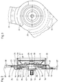
- a vehicle seat 1 as shown in FIG. 1 has a seat part 2 and a backrest 4 arranged on it, usually pivotally and fixably via articulated fittings 3 provided on both sides.
- a fixed joint part 5 attached to the seat part 2 is attached to a frame 6 of the former, usually by screwing, whereas a pivotable joint part 7 is arranged on the frame of the backrest 4 by screwing, riveting or welding.
- a pinion 10 produced by extrusion and a similarly produced internal ring gear 11 of an articulated fitting 9 having an eccentric planetary gear according to FIGS. 2 and 3 are designed as round plates and are mounted in a known manner on a pivot axis 13, namely the pinion 10 on an eccentric bearing area 14 and the inner ring gear 11 on a central bearing area 15.
- the number of teeth of the pinion 10 is one tooth less than that of the inner ring gear 11 and thus the tip circle of the pinion 10 is smaller by the tooth height than the root circle of the inner ring gear 11, the measure of the eccentricity of the eccentric bearing area 14 corresponds approximately to this difference and as a result there is self-locking between the pinion 10 and the internal ring gear 11, as is known.
- connection area 44 With the pinion 10 by means of a connection area 44 is a fixed corresponding to the fixed joint part 5 of FIG. 1 2 and 3 connected by resistance welding 18 and with the latter also by means of resistance welding 19 a guide plate 21 comprising the inner ring gear 11 with its pivotable joint part 23 by means of a segment region 20 with bearing play and thus holding axially.
- This inner joint ring 11 is this pivotable joint part 23, corresponding to the pivotable hinge part 7 according to FIG. 1, also connected by means of resistance welding 24 by means of a connection area 57 and to it, via a resistance welding 25, a guide plate 26 also comprising the pinion 10 via the fixed hinge part 17 in a segment area 22 with bearing play and thus holding connected.
- the rotary movement initiated via the handwheel 30 is transmitted to the other-side joint fitting of the vehicle seat 1 by means of a stub shaft (not shown).
- a bearing end face 33 of the pinion 10 and an abutting bearing end face 34 of the internal ring gear 11 lie on a center 31 of the external toothing 35 of the pinion 10 and the internal toothing 36 of the internal ring gear 11, so that when the eccentric planetary gear is loaded on the pinion 10 and the Internal ring gear 11 occurring Tooth pressures in each case only exert an equal, small, mutually canceling tilting moment with respect to the pivot axis 13 with respect to the bearing conditions, as a result of which the angular position of the pivot axis 13 within the eccentric planetary gear changes only very little under load, which is complementary to the lateral full engagement conditions of the Teeth 35 and 36 always have a favorable effect.
- the guide plates 21 and 26 can be replaced by collar screws arranged on the fixed joint part 17 or pivotable joint part 23 and axially abutting on the swivel joint part 23 or on the fixed joint part 17, as will be described later is described.
- the manufacture of the toothing bodies 10 and 11 as round blanks offers the advantage, due to its symmetrical design, of being able to be produced as particularly round and plan-accurate parts without cutting, which, in addition to the often required hardening or tempering, in contrast to the fittings produced in one piece with the connecting plates , is not the case to this extent, which means that the function and mode of operation of the articulated fittings 3 equipped with eccentric planetary gears are very smooth and smooth.
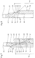
- a thicker starting material thickness 37, or, for example, 3.5 mm, of the pinion 10 and the internal ring gear 11 has an effect in relation to the substantially thinner material thickness 38, for example 1.8 mm
- the joint parts also taking into account a weight limit can be made larger, so that in this way the forces in their connections to the seat and backrest frames, which are made in relatively thin sheet metal thicknesses, become correspondingly smaller when the joint fitting is loaded, and these connections are thus made more solid by a more harmonious transition, thus preventing the safety of the seat Breakage, especially in the event of a crash, is increased without the use of large amounts of material.
- a tooth width 41 corresponds to the starting material thickness 37, the inner edge of the external toothing 35 coinciding with an outer material surface 42 thereof, and thus an upper region of the web 43 to the connecting region 44 of the pinion 10 about the starting material thickness 37 assumes an offset position , as it clearly shows Fig. 4.
- the eccentric bearing area 14 is widened by about 60% to the starting material thickness 37 by means of a molded-on hub 45, so that as a result the bearing conditions are further improved both in terms of the surface pressure and against a tilting position on the pivot axis 13.
- a safe resistance weld 18 is achieved.
- the material volume for the welding ring 46 is made available by pressing in a ring groove 47 on the other side.
- the extrusion process in this example produces a continuous material ring region 27 with a thickness 51 of approximately 40% or more of the starting material thickness 37, starting with a diameter 48 which is correspondingly larger than the tip circle of the external toothing 35 to which, starting from the size of the root diameter of the external toothing 35 at an angle ⁇ of approximately 30 °, a conical ring region 52 forms a gradual transition to the wall of the web 43 and thus creates a favorable stress curve.
- the thickness 51 of approximately 40% of the starting material thickness 37 can be selected within the scope of the invention, depending on the production and use conditions and the material quality and treatment, between a value of 28 to 50% and more.
- the material portions required for this design and for the full formation of the teeth are formed both by those portions between the pressed teeth of the external toothing 35 on the opposite side, i.e. the tooth gaps, and by the material portions of a pressed-in, free circular ring area 49 with the diameter 48 , which exceeds the tip circle of the external toothing 35.
- the material content, which is caused by indentation a corresponding annular groove 53 is displaced, as is provided on the side of the toothing 36 below it, depending on the selected dimensions of the thickness 51 and the circular ring region 49.
- a corresponding embodiment of the starting material thickness 37 which improves the mounting of the same on the pivot axis 13, can also be seen compared to the extended central bearing region 15, in that a hub 55, which increases the bearing length by about 60%, can also be seen here by the extrusion process is generated.
- a welding ring 46 is also formed for the resistance welding 24.
- a connection area 57 with the subsequent internal toothing 36 is here equally offset by the tooth width 41 with respect to a web 58 of the internal toothed ring 11 by the starting material width 37, so that here too the tooth width 41 corresponds to the starting material thickness 37.
- a fully closed material ring region 61 in a thickness 59 is formed from 35% of the starting material thickness 37, so that the internal toothing 36 laterally for transmitting the high forces in the event of a crash is fully attached.
- a conical ring area 56 adjoins the material ring area 61 on the outside as a gradual transition to the connection area 57, and on the inside it likewise joins the web 58 gradually by means of a cone ring area 63 at an angle of 30 to 45 °, all edges of the transitions being rounded 39 can be executed.
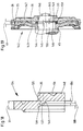
- the pinion 10 and the internal ring gear 11 can also be designed such that the displacement or stamping of their external and internal toothing to the connection regions 44 or 57 or to the web 43 is carried out somewhat larger than corresponds to the starting material thickness 37, in order to obtain an enlarged tooth width, as is illustrated in FIGS. 7 and 8.
- a tooth width 68 of an external toothing 72 is made approximately 10% larger than corresponds to the starting material thickness 37.
- a closed material ring area 69 with a thickness 73 from 36% of the starting material thickness 37 is produced to the side of the external toothing 72, to which the external toothing 72 is thus also firmly connected in this exemplary embodiment.
- This material ring area 69 is extended inwards by a conical ring area 74, which ends at the web 43 as a transition at a correspondingly flat angle at an angle ⁇ of approximately 30 °.
- the transition from the material ring area 69 to the connection area 44, as with the pinion 11, is also gradual, as shown by the flat, obliquely outward contour 66 of a transition area 65, this contour forms a chamfer 16 with the angle ⁇ .
- the edges and corners of the Areas to their neighbors are also executed with fillets 39.
- a tension-balanced connection of the external toothing 72 is also present in this pinion 67, both to the outer connection region 44 and to the web 43, the tooth bases being connected over their full width.
- the slightly higher bending load due to the increased tooth width 68 is transferred easily and with little stress peaks.
- the material portions required for the areas 65, 69 and 74 are taken from the external toothing 72, the free circular ring area 71, the diameter 70 of which is larger than the external toothing 72, in addition to the portions of the tooth gaps which are not pressed through or are, depending on the choice of the dimensions of the Annular area 71 and the conical ring area 74, as in all other inventive exemplary embodiments, made available by pressing in an annular groove 53 below the external toothing 71.
- a conical ring region 79 to the web 58 gradually adjoins this material ring region 77 at a flat angle ⁇ of approximately 30 °, with roundings 39 smoothing the shape.
- On the outside it has a diameter 64 which exceeds the root diameter of the internal toothing 78.
- the material parts required for this design are also added to the parts of the tooth gaps by displacement of a free conical ring area 75 drawn in dash-dotted lines and hatched accordingly, and likewise, if necessary, by an annular groove 60 on the side of the internal toothing 78.
- both a pinion region 81 with a connecting plate 82 to a fixed joint part 83 and an internal ring gear region 84 with a connecting plate 85 to a pivotable joint part 86 are each made in one piece by cold extrusion, in the joint parts 83 and 86, the center 31 of the external toothing 35 and the internal toothing 36, as in the exemplary embodiment according to FIG. 2, also lie axially at the level of the mutually abutting bearing end faces 33, 34 of both joint parts.
- the fixed and pivotable hinge part 83 and 86 is, as with the corresponding corresponding hinge parts 5 and 7 according to FIG. 1, each connected to seat parts, for which purpose the holes 89 are used.
- the external toothing 35 is connected to a continuous material ring area 92 in a thickness 91 of approximately 40% of the starting material thickness 37 and also thickening it , a flat material ring region 100 in a thickness 105 of approximately a quarter of the thickness 91, in which impressions 102 of the same depth are provided in the form of the tooth heads of the external toothing 35, also in terms of position, in accordance with them.
- the high-lying parts 97 remaining between the impressions 102 are connected by the inclined connecting parts 99 running around them up to the impressions 102 with the web 43.
- the material required for the full embossing of the teeth of the external toothing 35 and the material ring area 100 of the oblique parts 99 and 103 is also here, in addition to the portions available between the teeth of the pressed-in external toothing 35, material taken from a free circular ring area 93 of a diameter 101, is larger than the tip circle of the external toothing 35, as well as made available by the impressions 102 and the further free spaces and the material portion of the annular groove 53 on the side of the toothing.
- the impressions 102 can be used to achieve a particularly favorable, stress-relieving shape can also be designed in a wave-like shape 104 as rounded in the sole and in the upper transitions.
- a pinion 110 in the further inventive embodiment of a pinion 110 according to FIGS. 14 and 15, those for connecting the external toothing 35 in the width of the starting material thickness 37 to a closed material ring area 111 in a thickness 105 of at least 28% of the starting material thickness 37, and for creating a subsequent conical ring area 112, which runs from the material ring area 111 to the web 43 at a flat angle at an angle ⁇ of approximately 35 °, and for a quantity of material required for the material ring area 111 complementing the material ring area 111, a free circular ring area 114 and oblique impressions 117 are formed in a shape 119 corresponding to the teeth of FIG External teeth 35 are also impressed into the material ring area 109 at the angle ⁇ and which connect to the cone ring area 112.
- the free circular ring area 114 with a diameter 116 with its diameter 113, extends beyond the tip circle of the external toothing 35 to the extent required, the conical ring area 112 starting with a diameter 115 somewhat smaller than the root circle.
- the material ring region 109 has a thickness 96 of approximately 28% of the starting material thickness 37.
- 16 and 17 has a pinion 120 with an external toothing 121, the tooth width 122 of which is approximately 10% smaller than the starting material width 37.
- the external toothing 121 is solidly connected on the side.
- a conical ring area 125 with a diameter 128 adjoins the material ring area 123, tapering to the web 129.
- Flat impressions 131 are embossed in depth and in shape 130 as well as the position of the teeth of the external toothing 121 in the material ring area 124.
- the material for the circular ring regions 123 and 124 and the conical ring region 125 is removed from these impressions and a free circular ring region 126 with a diameter 127 that exceeds the tip circle of the external toothing 121, and by pressing in an annular groove 53 on the toothing side.
- the associated internal ring gear which is not described here, is adapted accordingly with regard to the tooth width, the narrower tooth width 122 in conjunction with the inexpensive bearing design and the inventive lateral tooth connection and corresponding choice of materials not reducing the performance, since the risk of breakage for the teeth in the event of overload is more critical than the surface pressure on the tooth flanks.
- the external toothing 35 is connected laterally to a material ring region 135 with a thickness 136 from 28% of the starting material thickness 37. It is followed laterally by a material ring area 137 interrupted by impressions, approximately in a thickness 138 of approximately 20% of the starting material width 37, in the circular ring area of the external toothing 35.
- the impressions 139 of the material ring area 137 lie, viewed from the side, with the teeth of the external toothing 35 in alignment, they can have the shape of the external toothing 35, but they can also be pressed in in a corrugated and rounded shape similar to the shape 104 according to FIG. 12.
- a conical ring area 140 adjoins the material ring area 135, which creates a gradual transition to the web 43 for the former.
- the material portions required for the material ring regions 135 and 137 and the cone ring region 141 are provided analogously to the examples described above.
- FIG. 19 An example of a joint fitting 142 with a widened eccentric planetary gear is shown in FIG. 19, namely as a partial section, the partial areas not shown correspondingly corresponding to those in FIG. 2.
- an eccentric bearing region 144 begins, lying from a center 31 of the external and internal toothing 35 and 36 at a distance 145 of almost half the tooth width 41.
- a central bearing area 146 of an inner ring gear 147 begins lying away from the center 31, the inner ring gear 147 with a bearing face 148 coming into contact with a bearing face 149 of the pivot axis 150.
- the pinion 143 and the internal ring gear 147 can be supported axially inwards by a spacer ring 151 with bearing play.
- the eccentric bearing area 144 and the central bearing area 146 are also widened by hubs 45 and 55, respectively, of the starting material thickness 37. Here, too, a full inner compensation of the tilting moments is achieved.
- joint fittings for adjustable backrests - in particular for motor vehicles - are created which, due to their considerable advantages, in particular with regard to the load-bearing capacity and resilience, as well as with regard to safety and functionality, while at the same time being highly economical, save tool costs, make a diverse and broad application on the relevant technical Allow territory.
Claims (15)
- Articulation pour sièges avec dossier réglable, en particulier pour véhicules automobiles, pour laquelle une partie articulation (5) rigide, associée à la partie assise (2), et une partie articulation (7) pivotante, reliée au dossier (4), constituent au moyen d'un jeu d'engrenages planétaires excentrique, un réglage d'inclinaison et un dispositif de blocage de position, les dentures du pignon (10) afférent et de la couronne à denture intérieure (11) étant produites par refoulement ou moyen d'un processus de pressage à fluage à froid, avec des largeurs de dent à peu près égales à l'épaisseur du matériau initial, des zones annulaires de matériau (27, 61, 69, 77, 92, 111, 123, 135) en forme d'anneaux de cercle, continues, étant constituées dans les zones voisines axialement de la denture (35, 36, 72, 78, 121) du pignon (10, 67, 110, 120, 134) et de la couronne à denture intérieure (11, 76, 137), caractérisée en ce que les zones annulaires de matière (27, 61, 69, 77, 92, 111, 123, 135) ont une épaisseur (51, 54, 59, 73, 91, 105, 132, 136) d'au moins 28 % de l'épaisseur initiale (37) de la matière, en ce qu'aux zones annulaires de matière (27, 61, 69, 77, 92, 111, 123, 135) se raccordent, en faisant un angle plat, au niveau des âmes (43, 58, 129) des zones de matière (52, 56, 63, 74, 79, 99, 112, 125, 140) en forme d'anneaux coniques et en ce que les faces frontales de tourillonnement (33, 34) du pignon (10) et de la couronne à denture intérieure (11), dans le plan médian (31) de la denture (35, 36) du pignon (10) et de la couronne à denture intérieure ou du plan médian (31), sont éloignées de la même distance (115) en étant respectivement opposées.
- Articulation selon la revendication 1, caractérisée en ce que les parties de denture (10, 11) sont, soit des flans circulaires, indépendants, soit sont réalisés d'un seul tenant avec les parties d'articulation ou de ferrure d'articulation.
- Articulation selon la revendication 1 ou 2, caractérisée en ce que les proportions en matière des âmes (43, 58, 129) sont totalement ou partiellement constituées tant par les entredents se trouvant de l'aute côté et situés entre les dentures (35, 36, 72, 78, 121) obtenues par pressage, que par des zones en anneaux de cercle (49, 71, 93, 114, 126) libres, creusées par le refoulement sur le côté opposé aux dentures (35, 36, 72, 78, 121), respectivement sont en plus fournies par des gorges annulaires (53, 60, 62) obtenues par le refoulement et situées du côté de la denture ou bien du côté opposé, ainsi que par des empreintes (102, 104, 131, 139).
- Articulation selon l'une des revendications 1 à 3, caractérisée en ce que la largeur de dent (41) est à peu près égale à l'épaisseur initiale (37) du matériau ou bien la largeur de dent (68), respectivement (122), est d'environ 10 % supérieure ou inférieure à l'épaisseur initiale (37) du matériau.
- Articulation selon l'une des revendications 1 à 4, caractérisée en ce que les zones de tourillonnement excentrique (14, 15) des pignons (10, 67, 90, 110, 120, 134) et des parties d'articulation (83, 86) ainsi que des couronnes à denture intérieure (11, 76, 137) sont réalisées avec des moyeux (45, 55), qui sont élargis dans leur longueur au moins à 1,6 fois l'épaisseur initiale (37) du matériau.
- Articulation selon l'une des revendications 1 à 5, caractérisée en ce que, pour un pignon (10) et une couronne à denture intérieure (11), les épaisseurs (51, 59) des zones annulaires de matériau (27, 61) sont réalisées à partir de 35 % de l'épaisseur initiale (37) du matériau et la zone d'anneau conique (52) s'y raccordant se raccorde à l'âme (43) en faisant un angle (α) d'environ 30° et la zone en anneau conique (63) est réalisée progressivement et continuement vis-à-vis de l'âme (58) sous un angle compris dans la plage allant de 30 à 45°.
- Articulation selon l'une des revendications 1 à 5, caractérisée en ce que pour un pignon (90) la zone annulaire (92) de matériau se transforme avec une épaisseur (91) d'environ 40 % de l'épaisseur initiale (37) du matériau et pour un diamètre extérieur (101) supérieur au diamètre du cercle de tête de la denture extérieure (35), en la zone de raccordement (44), une zone annulaire (100) de matériau se raccordant latéralement, zone dans laquelle sont imprimés à l'opposé des profils de denture de la denture extérieure (35), des enfoncements (102) ayant à peu près leur profil, l'enfoncement se faisant parallèlement jusqu'à la zone annulaire (92) de matériau, des zones annulaires coniques (99) de pourtour entourant les parties (97) relevées subsistantes jusqu'à l'âme (43), de façon progressive et en s'y raccordant, et des parties (103) obliques, orientées vers l'intérieur et se raccordant aux enfoncements (102), formant des transitions vers l'âme (43) et les zones annulaires coniques (99), ainsi que les parties (103), s'étendant sous un angle (γ) d'environ 40° par rapport à l'âme (43).
- Articulation selon l'une des revendications 1 à 5, caractérisée en ce qu'au niveau d'un pignon (110) se raccordent à la zone annulaire de matériau (111) avec à peu près une épaisseur (10b) d'au moins 28 % de l'épaisseur initiale (37) du matériau, latéralement, une zone annulaire de matériau (109) ayant une épaisseur (96) d'environ 28 % de l'épaisseur initiale (37) du matériau et, vers l'intérieur, une zone annulaire conique (112), qui s'étend vers l'âme (43) avec un angle (β) d'environ 35°, des enfoncements (117) obliques, opposés à la denture (35), étant réalisés dans celle-ci par refoulement et selon sa forme, avec un angle (δ), et une zone annulaire circulaire (114) libre ayant extérieurement un diamètre (113) supérieur à celui du cercle de tête de la denture extérieure (35).
- Articulation selon l'une des revendications 1 à 5, caractérisée en ce qu'au niveau d'un pignon (120) se raccorde à la zone annulaire de matière (123), avec une épaisseur (132) de 40 % et plus de l'épaisseur initiale (37) du matériau et avec un diamètre intérieur (128) inférieur à celui du cercle du pied de la denture extérieure (121), latéralement, une zone annulaire de matériau (124) ayant une épaisseur (133) d'environ 25 % de l'épaisseur initiale (37) du matériau avec un diamètre (127) supérieur à celui du cercle de tête, des empreintes (131) plates se présentant sous la forme et à la position des dents de la denture extérieure (121) étant creusées par refoulement dans cette zone annulaire de matériau (124).
- Articulation selon l'une des revendications 1 à 5, caractérisée en ce qu'au niveau d'un pignon (134) se raccorde à une zone annulaire de matériau (135) avec, latéralement, une zone annulaire de matériau (137) avec une épaisseur (136) à partir de 28 % de l'épaisseur initiale (37) du matériau, interrompue par des empreintes (139), avec une épaisseur partant de 20 % de l'épaisseur initiale (37) du matériau, les empreintes (139) correspondant pour leur forme et leur position aux dents de la denture extérieure (35), ou bien celles-ci présentant une forme arrondie, interrompue par des empreintes (139)
- Articulation selon l'une des revendications 1 à 10, caractérisée en ce que les angles et les arêtes des pignons, des zones de pignon et de couronne à denture intérieure (81, 84) ainsi que les couronnes à denture intérieure (11, 76, 137) sont réalisés de part et d'autre des zones des dentures (35, 36, 72, 78, 121) de façon arrondie ou bien avec des chanfreins (16) d'un angle d'environ 15°.
- Articulation selon l'une des revendications 1 à 11, caractérisée en ce que le pignon (10) et la couronne à denture intérieure (11) sont réalisés sous forme de flans circulaires ayant une épaisseur initiale de matériau (37) plus forte, de préférence de 3,5 mm, et avec une partie d'articulation (17) rigide, respectivement avec une partie d'articulation (23) pivotante ayant une épaisseur de matériau (38) moindre, de préférence d'environ 1,8 mm, en étant reliés rigidement par soudure, rivetage, vissage, et en ce que sur les parties d'articulation (17, 23) sont disposées respectivement rigidement des tôles de guidage (21, 26), qui viennent en appui frontal avec la partie d'articulation (23) pivotante, respectivement sur le pignon (10) avec la partie d'articulation (17) rigide, par leurs zones de segment (20, respectivement 22), en laissant subsister un jeu.
- Articulation selon l'une des revendications 1 à 12, caractérisée en ce que le pignon (10, 67, 90, 110, 120, 125) fou et la couronne à denture intérieure (11, 76) folle sont pourvus frontalement, dans leurs zones de raccordement (44, 57), sur la face opposée aux dentures (35, 36, 72, 121), d'anneaux de soudage (46) ayant des sections transversales triangulaires, pointues ou arrondies.
- Articulation selon l'une des revendications 1 à 13, caractérisée en ce qu'une zone de pignon (81) et une zone de couronne à denture intérieure (84), dont les dentures (35, 36) ainsi que les âmes et les conditions de tourillonnement correspondent à celles du pignon (10) et de la couronne à denture intérieure (11), sont réalisées respectivement d'un seul tenant avec une partie d'articulation (83) rigide, respectivement une partie d'articulation (86) pivotante, et un ou deux axes ou boulons de guidage (87) étant respectivement disposés avec chacune des parties d'articulation (83, 86), ces axes ou boulons étant placés en opposition de l'autre partie d'articulation leur étant chaque fois associée dans leur zone de raccordement avec la face intérieure de leur tête, avec peu de jeu, en se chevauchant avec une zone (88) à contour extérieur centré ou bien en ce que, au lieu dos boulons de guidage, on utilise des tôles de guidage (21, 26).
- Articulation selon l'une des revendications 1 à 14, caractérisée en ce qu'entre les faces frontales de tourillonnement (148, 139) du pignon (143) et la couronne à denture intérieure (147) se trouve une bague d'espacement (151) ayant un jeu de tourillonnement.
Applications Claiming Priority (2)
| Application Number | Priority Date | Filing Date | Title |
|---|---|---|---|
| DE4117497 | 1991-05-28 | ||
| DE4117497A DE4117497C2 (de) | 1991-05-28 | 1991-05-28 | Verstellbeschlag für Sitze mit neigungsverstellbarer Rückenlehne, insbesondere für Kraftfahrzeug-Sitze |
Publications (2)
| Publication Number | Publication Date |
|---|---|
| EP0517332A1 EP0517332A1 (fr) | 1992-12-09 |
| EP0517332B1 true EP0517332B1 (fr) | 1996-08-21 |
Family
ID=6432659
Family Applications (2)
| Application Number | Title | Priority Date | Filing Date |
|---|---|---|---|
| EP92910777A Pending EP0586463A1 (fr) | 1991-05-28 | 1992-05-22 | Armature articulee pour sieges munis d'un dossier inclinable, notamment pour les automobiles |
| EP92201598A Expired - Lifetime EP0517332B1 (fr) | 1991-05-28 | 1992-05-22 | Ferrure d'articulation pour sièges à dossier réglable en inclinaison, en particulier pour véhicules automobiles |
Family Applications Before (1)
| Application Number | Title | Priority Date | Filing Date |
|---|---|---|---|
| EP92910777A Pending EP0586463A1 (fr) | 1991-05-28 | 1992-05-22 | Armature articulee pour sieges munis d'un dossier inclinable, notamment pour les automobiles |
Country Status (12)
| Country | Link |
|---|---|
| US (1) | US5531504A (fr) |
| EP (2) | EP0586463A1 (fr) |
| JP (1) | JPH06507587A (fr) |
| AT (1) | ATE141554T1 (fr) |
| BR (1) | BR9205690A (fr) |
| CZ (1) | CZ281034B6 (fr) |
| DE (2) | DE4117497C2 (fr) |
| ES (1) | ES2091396T3 (fr) |
| PL (1) | PL168261B1 (fr) |
| SI (1) | SI9200089A (fr) |
| TR (1) | TR25845A (fr) |
| WO (1) | WO1992021531A1 (fr) |
Families Citing this family (19)
| Publication number | Priority date | Publication date | Assignee | Title |
|---|---|---|---|---|
| DE4140720C2 (de) * | 1991-12-10 | 1995-10-12 | Naue Johnson Controls Eng | Verfahren zur Herstellung von Stirnrädern und zugehörigen Innenzahnkränzen durch kombinierte Feinstanz- und Fließpreßarbeitsgänge |
| DE4204693C2 (de) * | 1992-02-17 | 1996-10-31 | Johnson Controls Naue Engineer | Verstellbeschlag mit Exzenter-Planetengetriebe für Kraftfahrzeugsitze |
| FR2759333B1 (fr) * | 1997-02-11 | 1999-04-16 | Faure Bertrand Equipements Sa | Mecanisme d'articulation pour siege de vehicule, et siege de vehicule comportant un tel mecanisme |
| US6296311B1 (en) | 1999-10-29 | 2001-10-02 | Fisher Dynamics Corporation | Constant engagement infinite recliner |
| JP4479329B2 (ja) * | 2004-04-26 | 2010-06-09 | アイシン精機株式会社 | 車両用シートリクライニング装置及びその製造方法 |
| FR2872105B1 (fr) * | 2004-06-24 | 2007-12-21 | Faurecia Sieges Automobile | Mecanisme d'articulation pour siege automobile et siege comportant un tel mecanisme |
| JP4916155B2 (ja) * | 2004-12-28 | 2012-04-11 | デルタ工業株式会社 | リクライニング装置 |
| FR2900605B1 (fr) * | 2006-05-05 | 2008-07-11 | Faurecia Sieges Automobile | Procede de fabrication d'un mecanisme d'articulation pour siege de vehicule, mecanisme d'articulation fabrique selon un tel procede et siege de vehicule comprenant un tel mecanisme d'articulation |
| EP1900452B1 (fr) * | 2006-09-13 | 2012-05-30 | Feintool Intellectual Property AG | Procédé de renforcement d'un paroi d'une garniture tridimensionnelle |
| JP5177134B2 (ja) * | 2007-05-08 | 2013-04-03 | トヨタ紡織株式会社 | 連結装置 |
| DE112009000118B4 (de) * | 2008-01-17 | 2014-12-18 | Fisher Dynamics Corp. | Verstellmechanismus und Sitzbaugruppe |
| PL2300266T3 (pl) * | 2008-06-13 | 2017-06-30 | Brose Fahrzeugteile Gmbh & Co. Kommanditgesellschaft, Coburg | Okucie przestawne |
| DE102010007955B4 (de) * | 2010-02-12 | 2014-08-21 | Johnson Controls Gmbh | Verfahren zur Herstellung eines Bauteils sowie Vorrichtung |
| DE102010022615B4 (de) * | 2010-05-31 | 2012-01-05 | Keiper Gmbh & Co. Kg | Beschlag für einen Fahrzeugsitz und Fahrzeugsitz |
| US9296315B2 (en) | 2013-02-26 | 2016-03-29 | Fisher & Company, Incorporated | Recliner mechanism with backdriving feature |
| DE102013216242A1 (de) * | 2013-08-15 | 2015-02-19 | Brose Fahrzeugteile Gmbh & Co. Kg, Coburg | Verstellantrieb für Verstelleinrichtungen eines Fahrzeugsitzes |
| US9902297B2 (en) | 2014-06-11 | 2018-02-27 | Fisher & Company, Incorporated | Latch mechanism with locking feature |
| JP6682300B2 (ja) * | 2016-03-04 | 2020-04-15 | シロキ工業株式会社 | シートリクライニング装置 |
| DE102016204171A1 (de) * | 2016-03-14 | 2017-09-14 | Sitech Sitztechnik Gmbh | Fahrzeugsitz mit einem Verstellbeschlag mit einer doppelten Hohlradanbindung an einer Rückenlehnenstruktur eines Fahrzeugsitzes |
Family Cites Families (10)
| Publication number | Priority date | Publication date | Assignee | Title |
|---|---|---|---|---|
| DE1680128A1 (de) * | 1951-01-28 | 1971-11-11 | Keiper Fa F | Gelenkbeschlag fuer Sitze mit verstellbarer Lehne,insbesondere Kraftfahrzeugsitze |
| DE2834492C3 (de) * | 1978-08-07 | 1994-07-28 | Keiper Recaro Gmbh Co | Gelenkbeschlag für einen Sitz mit verstellbarer Rückenlehne, insbesondere Kraftfahrzeugsitz |
| DE3226714C2 (de) * | 1982-07-16 | 1986-09-18 | P.A. Rentrop, Hubbert & Wagner Fahrzeugausstattungen Gmbh & Co Kg, 3060 Stadthagen | Gelenkbeschlag für Kraftfahrzeugsitze mit verstellbarer Lehne |
| CS231432B1 (en) * | 1982-11-25 | 1984-11-19 | Jan Babak | Planet mechanism |
| DE3244399A1 (de) * | 1982-12-01 | 1984-06-07 | Rentrop Hubbert & Wagner | Gelenkbeschlag fuer kraftfahrzeugsitze mit verstellbarer lehne |
| JPS6137849U (ja) * | 1984-08-10 | 1986-03-08 | シロキ工業株式会社 | リクライニング装置 |
| DE3624018C2 (de) * | 1986-07-16 | 1998-07-02 | Keiper Gmbh & Co | Lehnenneigungseinstellbeschlag für Sitze, insbesondere Kraftfahrzeugsitze |
| FR2614810B1 (fr) * | 1987-05-05 | 1992-01-03 | Cousin Cie Ets A & M Freres | Satellite double a denture renforcee pour articulation micrometrique utilisee plus specialement dans les sieges de vehicules |
| DE3723710C2 (de) * | 1987-07-17 | 1996-08-14 | Keiper Recaro Gmbh Co | Verstellbeschlag für Sitze mit verstellbarer Rückenlehne |
| FR2627437B1 (fr) * | 1988-02-23 | 1990-06-22 | Tubauto | Articulation continue irreversible pour siege |
-
1991
- 1991-05-28 DE DE4117497A patent/DE4117497C2/de not_active Expired - Fee Related
-
1992
- 1992-05-22 JP JP4509785A patent/JPH06507587A/ja active Pending
- 1992-05-22 US US08/142,406 patent/US5531504A/en not_active Expired - Fee Related
- 1992-05-22 PL PL92301118A patent/PL168261B1/pl unknown
- 1992-05-22 EP EP92910777A patent/EP0586463A1/fr active Pending
- 1992-05-22 CZ CZ93509A patent/CZ281034B6/cs unknown
- 1992-05-22 BR BR9205690A patent/BR9205690A/pt active Search and Examination
- 1992-05-22 WO PCT/EP1992/001145 patent/WO1992021531A1/fr active IP Right Grant
- 1992-05-22 EP EP92201598A patent/EP0517332B1/fr not_active Expired - Lifetime
- 1992-05-22 ES ES92201598T patent/ES2091396T3/es not_active Expired - Lifetime
- 1992-05-22 DE DE59206934T patent/DE59206934D1/de not_active Expired - Fee Related
- 1992-05-22 AT AT92201598T patent/ATE141554T1/de not_active IP Right Cessation
- 1992-05-26 SI SI19929200089A patent/SI9200089A/sl unknown
- 1992-05-27 TR TR92/0472A patent/TR25845A/xx unknown
Also Published As
| Publication number | Publication date |
|---|---|
| TR25845A (tr) | 1993-09-01 |
| BR9205690A (pt) | 1994-05-17 |
| DE59206934D1 (de) | 1996-09-26 |
| ATE141554T1 (de) | 1996-09-15 |
| US5531504A (en) | 1996-07-02 |
| SI9200089A (en) | 1992-11-27 |
| EP0586463A1 (fr) | 1994-03-16 |
| DE4117497A1 (de) | 1993-01-28 |
| ES2091396T3 (es) | 1996-11-01 |
| CZ281034B6 (cs) | 1996-05-15 |
| WO1992021531A1 (fr) | 1992-12-10 |
| PL168261B1 (pl) | 1996-01-31 |
| CZ50993A3 (en) | 1993-12-15 |
| EP0517332A1 (fr) | 1992-12-09 |
| JPH06507587A (ja) | 1994-09-01 |
| DE4117497C2 (de) | 1997-01-16 |
Similar Documents
| Publication | Publication Date | Title |
|---|---|---|
| EP0517332B1 (fr) | Ferrure d'articulation pour sièges à dossier réglable en inclinaison, en particulier pour véhicules automobiles | |
| DE10321712B4 (de) | Sitzverstellvorrichtung für einen Kraftfahrzeugsitz | |
| DE102004007043B3 (de) | Beschlag für einen Fahrzeugsitz | |
| EP2398671B1 (fr) | Ferrure pour siège de véhicule | |
| WO2013152996A1 (fr) | Palier libre pour mécanisme de direction | |
| DE3013304A1 (de) | Stellvorrichtung fuer sitze und fenster, insbesondere von kraftfahrzeugen | |
| DE102014208852C5 (de) | Doppelbeschlag für einen Fahrzeugsitz und Fahrzeugsitz | |
| DE2849542C2 (de) | Gelenkbeschlag für Sitze mit verstellbarer Rückenlehne, insbesondere Kraftfahrzeugsitze | |
| EP2663781A1 (fr) | Accouplement permettant une liaison à amortissement de deux parties d'arbre, en particulier d'un arbre de direction, arbre de direction correspondant, et procédé de production d'un accouplement correspondant | |
| DE2808954A1 (de) | Gelenkbeschlag fuer sitze mit verstellbarer rueckenlehne, insbesondere kraftfahrzeugsitze | |
| DE2834492C3 (de) | Gelenkbeschlag für einen Sitz mit verstellbarer Rückenlehne, insbesondere Kraftfahrzeugsitz | |
| DE3227222C1 (de) | Gelenkbeschlag fuer Sitze mit verstellbarer Rueckenlehne,insbesondere Kraftfahrzeugsitze | |
| DE3032374C2 (de) | Drehgelenk für Sitze mit verstellbarer Rückenlehne | |
| DE19956901A1 (de) | Einstellbarer Beschlag für eine Schwenkverstellung eines ersten Gelenkteils gegenüber einem zweiten Gelenkteil | |
| DE3118896C2 (de) | Drehgelenk, insbesondere für Sitze mit verstellbarer Rückenlehne | |
| DE2225757C3 (de) | Gelenk für eine verstellbare Rückenlehne eines Sitzes | |
| EP0001268B1 (fr) | Accouplement élastique | |
| EP0129030A2 (fr) | Articulation, en particulier pour sièges avec dossier réglable | |
| DE102004007045B3 (de) | Beschlag für einen Fahrzeugsitz | |
| DE4204693C2 (de) | Verstellbeschlag mit Exzenter-Planetengetriebe für Kraftfahrzeugsitze | |
| DE10343539B4 (de) | Förderband mit einer Antriebseinheit | |
| DE20321780U1 (de) | Förderband mit in Lagergehäusen pendelbar aufgenommenen Drehlagern | |
| DE19533453C2 (de) | Beschlag zur Neigungseinstellung der Rückenlehne eines Sitzes, insbesondere eines Kraftfahrzeugsitzes | |
| DE4329060C2 (de) | Vorrichtung zur Verstellung von Sitzen, insbesondere Kraftfahrzeugsitzen | |
| DE3339951C2 (de) | Antriebswelle für die Räder eines Kraftfahrzeugs, insbesondere eines Personenkraftwagens |
Legal Events
| Date | Code | Title | Description |
|---|---|---|---|
| PUAI | Public reference made under article 153(3) epc to a published international application that has entered the european phase |
Free format text: ORIGINAL CODE: 0009012 |
|
| AK | Designated contracting states |
Kind code of ref document: A1 Designated state(s): PT |
|
| 17P | Request for examination filed |
Effective date: 19921215 |
|
| 17Q | First examination report despatched |
Effective date: 19950130 |
|
| XX | Miscellaneous (additional remarks) |
Free format text: VERBUNDEN MIT 92910777.9/0586463 (EUROPAEISCHE ANMELDENUMMER/VEROEFFENTLICHUNGSNUMMER) DURCH ENTSCHEIDUNG VOM 16.03.95. |
|
| GRAG | Despatch of communication of intention to grant |
Free format text: ORIGINAL CODE: EPIDOS AGRA |
|
| GRAH | Despatch of communication of intention to grant a patent |
Free format text: ORIGINAL CODE: EPIDOS IGRA |
|
| GRAA | (expected) grant |
Free format text: ORIGINAL CODE: 0009210 |
|
| GRAH | Despatch of communication of intention to grant a patent |
Free format text: ORIGINAL CODE: EPIDOS IGRA |
|
| AK | Designated contracting states |
Kind code of ref document: B1 Designated state(s): AT BE CH DE DK ES FR GB GR IT LI LU MC NL PT SE |
|
| ITF | It: translation for a ep patent filed |
Owner name: BARZANO' E ZANARDO ROMA S.P.A. |
|
| PG25 | Lapsed in a contracting state [announced via postgrant information from national office to epo] |
Ref country code: NL Free format text: LAPSE BECAUSE OF FAILURE TO SUBMIT A TRANSLATION OF THE DESCRIPTION OR TO PAY THE FEE WITHIN THE PRESCRIBED TIME-LIMIT Effective date: 19960821 Ref country code: GR Free format text: LAPSE BECAUSE OF FAILURE TO SUBMIT A TRANSLATION OF THE DESCRIPTION OR TO PAY THE FEE WITHIN THE PRESCRIBED TIME-LIMIT Effective date: 19960821 Ref country code: DK Effective date: 19960821 |
|
| REF | Corresponds to: |
Ref document number: 141554 Country of ref document: AT Date of ref document: 19960915 Kind code of ref document: T |
|
| XX | Miscellaneous (additional remarks) |
Free format text: VERBUNDEN MIT 92910777.9/0586463 (EUROPAEISCHE ANMELDENUMMER/VEROEFFENTLICHUNGSNUMMER) DURCH ENTSCHEIDUNG VOM 16.03.95. |
|
| ET | Fr: translation filed | ||
| REF | Corresponds to: |
Ref document number: 59206934 Country of ref document: DE Date of ref document: 19960926 |
|
| REG | Reference to a national code |
Ref country code: ES Ref legal event code: FG2A Ref document number: 2091396 Country of ref document: ES Kind code of ref document: T3 |
|
| PG25 | Lapsed in a contracting state [announced via postgrant information from national office to epo] |
Ref country code: SE Effective date: 19961121 Ref country code: PT Effective date: 19961121 |
|
| GBT | Gb: translation of ep patent filed (gb section 77(6)(a)/1977) |
Effective date: 19961115 |
|
| NLV1 | Nl: lapsed or annulled due to failure to fulfill the requirements of art. 29p and 29m of the patents act | ||
| PG25 | Lapsed in a contracting state [announced via postgrant information from national office to epo] |
Ref country code: GB Effective date: 19970522 Ref country code: AT Free format text: LAPSE BECAUSE OF NON-PAYMENT OF DUE FEES Effective date: 19970522 |
|
| PG25 | Lapsed in a contracting state [announced via postgrant information from national office to epo] |
Ref country code: ES Free format text: LAPSE BECAUSE OF EXPIRATION OF PROTECTION Effective date: 19970523 |
|
| PG25 | Lapsed in a contracting state [announced via postgrant information from national office to epo] |
Ref country code: LU Free format text: LAPSE BECAUSE OF NON-PAYMENT OF DUE FEES Effective date: 19970531 Ref country code: LI Free format text: LAPSE BECAUSE OF NON-PAYMENT OF DUE FEES Effective date: 19970531 Ref country code: CH Free format text: LAPSE BECAUSE OF NON-PAYMENT OF DUE FEES Effective date: 19970531 Ref country code: BE Effective date: 19970531 |
|
| PLBE | No opposition filed within time limit |
Free format text: ORIGINAL CODE: 0009261 |
|
| STAA | Information on the status of an ep patent application or granted ep patent |
Free format text: STATUS: NO OPPOSITION FILED WITHIN TIME LIMIT |
|
| 26N | No opposition filed | ||
| BERE | Be: lapsed |
Owner name: NAUE/ JOHNSON CONTROLS ENGINEERING VERWALTUNGS G. Effective date: 19970531 |
|
| PG25 | Lapsed in a contracting state [announced via postgrant information from national office to epo] |
Ref country code: MC Effective date: 19971130 |
|
| GBPC | Gb: european patent ceased through non-payment of renewal fee |
Effective date: 19970522 |
|
| REG | Reference to a national code |
Ref country code: CH Ref legal event code: PL |
|
| PG25 | Lapsed in a contracting state [announced via postgrant information from national office to epo] |
Ref country code: FR Free format text: LAPSE BECAUSE OF NON-PAYMENT OF DUE FEES Effective date: 19980130 |
|
| PG25 | Lapsed in a contracting state [announced via postgrant information from national office to epo] |
Ref country code: DE Free format text: LAPSE BECAUSE OF NON-PAYMENT OF DUE FEES Effective date: 19980203 |
|
| REG | Reference to a national code |
Ref country code: FR Ref legal event code: ST |
|
| REG | Reference to a national code |
Ref country code: ES Ref legal event code: FD2A Effective date: 20010301 |
|
| PG25 | Lapsed in a contracting state [announced via postgrant information from national office to epo] |
Ref country code: IT Free format text: LAPSE BECAUSE OF NON-PAYMENT OF DUE FEES Effective date: 20050522 |