EP0517332B1 - Hinge fitting for seats with reclining backrests, particularly for motor vehicles - Google Patents
Hinge fitting for seats with reclining backrests, particularly for motor vehicles Download PDFInfo
- Publication number
- EP0517332B1 EP0517332B1 EP92201598A EP92201598A EP0517332B1 EP 0517332 B1 EP0517332 B1 EP 0517332B1 EP 92201598 A EP92201598 A EP 92201598A EP 92201598 A EP92201598 A EP 92201598A EP 0517332 B1 EP0517332 B1 EP 0517332B1
- Authority
- EP
- European Patent Office
- Prior art keywords
- thickness
- pinion
- annular
- region
- tooth
- Prior art date
- Legal status (The legal status is an assumption and is not a legal conclusion. Google has not performed a legal analysis and makes no representation as to the accuracy of the status listed.)
- Expired - Lifetime
Links
Images


Classifications
-
- B—PERFORMING OPERATIONS; TRANSPORTING
- B60—VEHICLES IN GENERAL
- B60N—SEATS SPECIALLY ADAPTED FOR VEHICLES; VEHICLE PASSENGER ACCOMMODATION NOT OTHERWISE PROVIDED FOR
- B60N2/00—Seats specially adapted for vehicles; Arrangement or mounting of seats in vehicles
- B60N2/02—Seats specially adapted for vehicles; Arrangement or mounting of seats in vehicles the seat or part thereof being movable, e.g. adjustable
- B60N2/22—Seats specially adapted for vehicles; Arrangement or mounting of seats in vehicles the seat or part thereof being movable, e.g. adjustable the back-rest being adjustable
- B60N2/225—Seats specially adapted for vehicles; Arrangement or mounting of seats in vehicles the seat or part thereof being movable, e.g. adjustable the back-rest being adjustable by cycloidal or planetary mechanisms
- B60N2/2252—Seats specially adapted for vehicles; Arrangement or mounting of seats in vehicles the seat or part thereof being movable, e.g. adjustable the back-rest being adjustable by cycloidal or planetary mechanisms in which the central axis of the gearing lies inside the periphery of an orbital gear, e.g. one gear without sun gear
-
- B—PERFORMING OPERATIONS; TRANSPORTING
- B60—VEHICLES IN GENERAL
- B60N—SEATS SPECIALLY ADAPTED FOR VEHICLES; VEHICLE PASSENGER ACCOMMODATION NOT OTHERWISE PROVIDED FOR
- B60N2/00—Seats specially adapted for vehicles; Arrangement or mounting of seats in vehicles
- B60N2/02—Seats specially adapted for vehicles; Arrangement or mounting of seats in vehicles the seat or part thereof being movable, e.g. adjustable
- B60N2/22—Seats specially adapted for vehicles; Arrangement or mounting of seats in vehicles the seat or part thereof being movable, e.g. adjustable the back-rest being adjustable
- B60N2/225—Seats specially adapted for vehicles; Arrangement or mounting of seats in vehicles the seat or part thereof being movable, e.g. adjustable the back-rest being adjustable by cycloidal or planetary mechanisms
Definitions
- articulated fittings for seats in particular for motor vehicles, with an inclinable backrest, each of which has an external fitting on the seat which is pivotally, adjustably and self-lockingly fixed by an eccentric planetary gear.
- both the web of the bearing with the internal ring gear of the joint part and the spur gear with its associated joint part are each produced in one piece in a combined fine stamping and extrusion process, the tooth widths are smaller than the material thickness of the joint parts according to the degree of expression. This difference is according to the devices supplied according to this invention as well as according to the Representations in the drawing, about 30%.
- the known DE-A-28 34 492 suggests placing the inside of the expressions in a plane with the outside of the joint part in the case of the joint parts also produced by extrusion, that is to say the tooth width is equal to the starting material thickness and the connection of the two parts only to produce by thin wall bridges, which on the sides of the fittings not used as rolling elements circulate the fully pronounced high tooth profiles present there, whereby extremely high, additional bending stresses are introduced as a result of this design.
- the tooth width of the supporting elements which are in turn produced by extrusion, is to be widened in relation to the starting material thickness, for which purpose the material components required for this purpose are made available by enlarging the toothing area pressed in opposite.
- the bending moment under load for the teeth is increased, and since the tooth base is not connected to the same extent in a widened manner, the stresses under load are thus increased.
- the invention specified in claim 1 is based on the problem of creating joint fittings of the type mentioned, equipped with an eccentric planetary gear, the toothing bodies of which are produced by cold extrusion, in which the load-bearing capacity, in particular in the event of a crash, by a good connection of the teeth in the case of a large cross-sectional difference, particularly in the endangered areas, as well as rugged transitions and thus avoiding stress peaks, in relation to the known designs, while maintaining their weight, dimensions and manufacturing costs, is substantially increased, for which purpose it is necessary, based on the width is that good lateral engagement conditions of the gears are always ensured even in the event of an overload and that there is a high level of operating comfort and good functional reliability.
- the advantages achieved by the invention consist in particular in that the teeth of the pinions and those of the internal ring gears are each attached or supported laterally in addition to the full connection to the tooth base by material-strong, closed, circular and also conical ring-shaped material areas, opposite to the teeth there are no jagged and / or only slight cross-sectional changes, which are additionally provided with gradual transitions, so that a high load capacity of these parts is achieved.
- This also contributes to the fact that the bearing and guide conditions of these rolling elements are improved on their pivot axis and with respect to one another against lateral tilting.
- the different voltages that occur are thereby substantially reduced and a uniform course of the same is achieved, with the result that particularly high voltage peaks that initiate premature breaks are avoided.
- the present relatively lower and more uniform bending stresses also counteract a lateral sliding of the toothings from one another, as a result of which favorable loading and engagement as well as surface pressure conditions are present, so that especially in the event of a crash, only permanent deformations occur, but largely breakage in the load-bearing parts
- the tooth bodies manufactured as blanks in the extrusion process have a high concentricity and plan accuracy due to their symmetrical shape even after hardening or tempering, they themselves can be made stronger due to their connection with the much larger, but correspondingly thinner-walled connecting joint parts, without having to use the entire material enlarge. They are therefore extremely economical.
- they are inexpensive to combine with several different connecting joint parts, so that these same blanks can always be produced in correspondingly large quantities for several applications and thus tool costs are saved, which increases their economy even further.
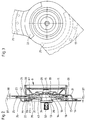
- a vehicle seat 1 as shown in FIG. 1 has a seat part 2 and a backrest 4 arranged on it, usually pivotally and fixably via articulated fittings 3 provided on both sides.
- a fixed joint part 5 attached to the seat part 2 is attached to a frame 6 of the former, usually by screwing, whereas a pivotable joint part 7 is arranged on the frame of the backrest 4 by screwing, riveting or welding.
- a pinion 10 produced by extrusion and a similarly produced internal ring gear 11 of an articulated fitting 9 having an eccentric planetary gear according to FIGS. 2 and 3 are designed as round plates and are mounted in a known manner on a pivot axis 13, namely the pinion 10 on an eccentric bearing area 14 and the inner ring gear 11 on a central bearing area 15.
- the number of teeth of the pinion 10 is one tooth less than that of the inner ring gear 11 and thus the tip circle of the pinion 10 is smaller by the tooth height than the root circle of the inner ring gear 11, the measure of the eccentricity of the eccentric bearing area 14 corresponds approximately to this difference and as a result there is self-locking between the pinion 10 and the internal ring gear 11, as is known.
- connection area 44 With the pinion 10 by means of a connection area 44 is a fixed corresponding to the fixed joint part 5 of FIG. 1 2 and 3 connected by resistance welding 18 and with the latter also by means of resistance welding 19 a guide plate 21 comprising the inner ring gear 11 with its pivotable joint part 23 by means of a segment region 20 with bearing play and thus holding axially.
- This inner joint ring 11 is this pivotable joint part 23, corresponding to the pivotable hinge part 7 according to FIG. 1, also connected by means of resistance welding 24 by means of a connection area 57 and to it, via a resistance welding 25, a guide plate 26 also comprising the pinion 10 via the fixed hinge part 17 in a segment area 22 with bearing play and thus holding connected.
- the rotary movement initiated via the handwheel 30 is transmitted to the other-side joint fitting of the vehicle seat 1 by means of a stub shaft (not shown).
- a bearing end face 33 of the pinion 10 and an abutting bearing end face 34 of the internal ring gear 11 lie on a center 31 of the external toothing 35 of the pinion 10 and the internal toothing 36 of the internal ring gear 11, so that when the eccentric planetary gear is loaded on the pinion 10 and the Internal ring gear 11 occurring Tooth pressures in each case only exert an equal, small, mutually canceling tilting moment with respect to the pivot axis 13 with respect to the bearing conditions, as a result of which the angular position of the pivot axis 13 within the eccentric planetary gear changes only very little under load, which is complementary to the lateral full engagement conditions of the Teeth 35 and 36 always have a favorable effect.
- the guide plates 21 and 26 can be replaced by collar screws arranged on the fixed joint part 17 or pivotable joint part 23 and axially abutting on the swivel joint part 23 or on the fixed joint part 17, as will be described later is described.
- the manufacture of the toothing bodies 10 and 11 as round blanks offers the advantage, due to its symmetrical design, of being able to be produced as particularly round and plan-accurate parts without cutting, which, in addition to the often required hardening or tempering, in contrast to the fittings produced in one piece with the connecting plates , is not the case to this extent, which means that the function and mode of operation of the articulated fittings 3 equipped with eccentric planetary gears are very smooth and smooth.
- a thicker starting material thickness 37, or, for example, 3.5 mm, of the pinion 10 and the internal ring gear 11 has an effect in relation to the substantially thinner material thickness 38, for example 1.8 mm
- the joint parts also taking into account a weight limit can be made larger, so that in this way the forces in their connections to the seat and backrest frames, which are made in relatively thin sheet metal thicknesses, become correspondingly smaller when the joint fitting is loaded, and these connections are thus made more solid by a more harmonious transition, thus preventing the safety of the seat Breakage, especially in the event of a crash, is increased without the use of large amounts of material.
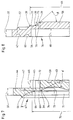
- a tooth width 41 corresponds to the starting material thickness 37, the inner edge of the external toothing 35 coinciding with an outer material surface 42 thereof, and thus an upper region of the web 43 to the connecting region 44 of the pinion 10 about the starting material thickness 37 assumes an offset position , as it clearly shows Fig. 4.
- the eccentric bearing area 14 is widened by about 60% to the starting material thickness 37 by means of a molded-on hub 45, so that as a result the bearing conditions are further improved both in terms of the surface pressure and against a tilting position on the pivot axis 13.
- a safe resistance weld 18 is achieved.
- the material volume for the welding ring 46 is made available by pressing in a ring groove 47 on the other side.
- the extrusion process in this example produces a continuous material ring region 27 with a thickness 51 of approximately 40% or more of the starting material thickness 37, starting with a diameter 48 which is correspondingly larger than the tip circle of the external toothing 35 to which, starting from the size of the root diameter of the external toothing 35 at an angle ⁇ of approximately 30 °, a conical ring region 52 forms a gradual transition to the wall of the web 43 and thus creates a favorable stress curve.
- the thickness 51 of approximately 40% of the starting material thickness 37 can be selected within the scope of the invention, depending on the production and use conditions and the material quality and treatment, between a value of 28 to 50% and more.
- the material portions required for this design and for the full formation of the teeth are formed both by those portions between the pressed teeth of the external toothing 35 on the opposite side, i.e. the tooth gaps, and by the material portions of a pressed-in, free circular ring area 49 with the diameter 48 , which exceeds the tip circle of the external toothing 35.
- the material content, which is caused by indentation a corresponding annular groove 53 is displaced, as is provided on the side of the toothing 36 below it, depending on the selected dimensions of the thickness 51 and the circular ring region 49.
- a corresponding embodiment of the starting material thickness 37 which improves the mounting of the same on the pivot axis 13, can also be seen compared to the extended central bearing region 15, in that a hub 55, which increases the bearing length by about 60%, can also be seen here by the extrusion process is generated.
- a welding ring 46 is also formed for the resistance welding 24.
- a connection area 57 with the subsequent internal toothing 36 is here equally offset by the tooth width 41 with respect to a web 58 of the internal toothed ring 11 by the starting material width 37, so that here too the tooth width 41 corresponds to the starting material thickness 37.
- a fully closed material ring region 61 in a thickness 59 is formed from 35% of the starting material thickness 37, so that the internal toothing 36 laterally for transmitting the high forces in the event of a crash is fully attached.
- a conical ring area 56 adjoins the material ring area 61 on the outside as a gradual transition to the connection area 57, and on the inside it likewise joins the web 58 gradually by means of a cone ring area 63 at an angle of 30 to 45 °, all edges of the transitions being rounded 39 can be executed.
- the pinion 10 and the internal ring gear 11 can also be designed such that the displacement or stamping of their external and internal toothing to the connection regions 44 or 57 or to the web 43 is carried out somewhat larger than corresponds to the starting material thickness 37, in order to obtain an enlarged tooth width, as is illustrated in FIGS. 7 and 8.
- a tooth width 68 of an external toothing 72 is made approximately 10% larger than corresponds to the starting material thickness 37.
- a closed material ring area 69 with a thickness 73 from 36% of the starting material thickness 37 is produced to the side of the external toothing 72, to which the external toothing 72 is thus also firmly connected in this exemplary embodiment.
- This material ring area 69 is extended inwards by a conical ring area 74, which ends at the web 43 as a transition at a correspondingly flat angle at an angle ⁇ of approximately 30 °.
- the transition from the material ring area 69 to the connection area 44, as with the pinion 11, is also gradual, as shown by the flat, obliquely outward contour 66 of a transition area 65, this contour forms a chamfer 16 with the angle ⁇ .
- the edges and corners of the Areas to their neighbors are also executed with fillets 39.
- a tension-balanced connection of the external toothing 72 is also present in this pinion 67, both to the outer connection region 44 and to the web 43, the tooth bases being connected over their full width.
- the slightly higher bending load due to the increased tooth width 68 is transferred easily and with little stress peaks.
- the material portions required for the areas 65, 69 and 74 are taken from the external toothing 72, the free circular ring area 71, the diameter 70 of which is larger than the external toothing 72, in addition to the portions of the tooth gaps which are not pressed through or are, depending on the choice of the dimensions of the Annular area 71 and the conical ring area 74, as in all other inventive exemplary embodiments, made available by pressing in an annular groove 53 below the external toothing 71.
- a conical ring region 79 to the web 58 gradually adjoins this material ring region 77 at a flat angle ⁇ of approximately 30 °, with roundings 39 smoothing the shape.
- On the outside it has a diameter 64 which exceeds the root diameter of the internal toothing 78.
- the material parts required for this design are also added to the parts of the tooth gaps by displacement of a free conical ring area 75 drawn in dash-dotted lines and hatched accordingly, and likewise, if necessary, by an annular groove 60 on the side of the internal toothing 78.
- both a pinion region 81 with a connecting plate 82 to a fixed joint part 83 and an internal ring gear region 84 with a connecting plate 85 to a pivotable joint part 86 are each made in one piece by cold extrusion, in the joint parts 83 and 86, the center 31 of the external toothing 35 and the internal toothing 36, as in the exemplary embodiment according to FIG. 2, also lie axially at the level of the mutually abutting bearing end faces 33, 34 of both joint parts.
- the fixed and pivotable hinge part 83 and 86 is, as with the corresponding corresponding hinge parts 5 and 7 according to FIG. 1, each connected to seat parts, for which purpose the holes 89 are used.
- the external toothing 35 is connected to a continuous material ring area 92 in a thickness 91 of approximately 40% of the starting material thickness 37 and also thickening it , a flat material ring region 100 in a thickness 105 of approximately a quarter of the thickness 91, in which impressions 102 of the same depth are provided in the form of the tooth heads of the external toothing 35, also in terms of position, in accordance with them.
- the high-lying parts 97 remaining between the impressions 102 are connected by the inclined connecting parts 99 running around them up to the impressions 102 with the web 43.
- the material required for the full embossing of the teeth of the external toothing 35 and the material ring area 100 of the oblique parts 99 and 103 is also here, in addition to the portions available between the teeth of the pressed-in external toothing 35, material taken from a free circular ring area 93 of a diameter 101, is larger than the tip circle of the external toothing 35, as well as made available by the impressions 102 and the further free spaces and the material portion of the annular groove 53 on the side of the toothing.
- the impressions 102 can be used to achieve a particularly favorable, stress-relieving shape can also be designed in a wave-like shape 104 as rounded in the sole and in the upper transitions.
- a pinion 110 in the further inventive embodiment of a pinion 110 according to FIGS. 14 and 15, those for connecting the external toothing 35 in the width of the starting material thickness 37 to a closed material ring area 111 in a thickness 105 of at least 28% of the starting material thickness 37, and for creating a subsequent conical ring area 112, which runs from the material ring area 111 to the web 43 at a flat angle at an angle ⁇ of approximately 35 °, and for a quantity of material required for the material ring area 111 complementing the material ring area 111, a free circular ring area 114 and oblique impressions 117 are formed in a shape 119 corresponding to the teeth of FIG External teeth 35 are also impressed into the material ring area 109 at the angle ⁇ and which connect to the cone ring area 112.
- the free circular ring area 114 with a diameter 116 with its diameter 113, extends beyond the tip circle of the external toothing 35 to the extent required, the conical ring area 112 starting with a diameter 115 somewhat smaller than the root circle.
- the material ring region 109 has a thickness 96 of approximately 28% of the starting material thickness 37.
- 16 and 17 has a pinion 120 with an external toothing 121, the tooth width 122 of which is approximately 10% smaller than the starting material width 37.
- the external toothing 121 is solidly connected on the side.
- a conical ring area 125 with a diameter 128 adjoins the material ring area 123, tapering to the web 129.
- Flat impressions 131 are embossed in depth and in shape 130 as well as the position of the teeth of the external toothing 121 in the material ring area 124.
- the material for the circular ring regions 123 and 124 and the conical ring region 125 is removed from these impressions and a free circular ring region 126 with a diameter 127 that exceeds the tip circle of the external toothing 121, and by pressing in an annular groove 53 on the toothing side.
- the associated internal ring gear which is not described here, is adapted accordingly with regard to the tooth width, the narrower tooth width 122 in conjunction with the inexpensive bearing design and the inventive lateral tooth connection and corresponding choice of materials not reducing the performance, since the risk of breakage for the teeth in the event of overload is more critical than the surface pressure on the tooth flanks.
- the external toothing 35 is connected laterally to a material ring region 135 with a thickness 136 from 28% of the starting material thickness 37. It is followed laterally by a material ring area 137 interrupted by impressions, approximately in a thickness 138 of approximately 20% of the starting material width 37, in the circular ring area of the external toothing 35.
- the impressions 139 of the material ring area 137 lie, viewed from the side, with the teeth of the external toothing 35 in alignment, they can have the shape of the external toothing 35, but they can also be pressed in in a corrugated and rounded shape similar to the shape 104 according to FIG. 12.
- a conical ring area 140 adjoins the material ring area 135, which creates a gradual transition to the web 43 for the former.
- the material portions required for the material ring regions 135 and 137 and the cone ring region 141 are provided analogously to the examples described above.
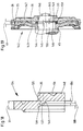
- FIG. 19 An example of a joint fitting 142 with a widened eccentric planetary gear is shown in FIG. 19, namely as a partial section, the partial areas not shown correspondingly corresponding to those in FIG. 2.
- an eccentric bearing region 144 begins, lying from a center 31 of the external and internal toothing 35 and 36 at a distance 145 of almost half the tooth width 41.
- a central bearing area 146 of an inner ring gear 147 begins lying away from the center 31, the inner ring gear 147 with a bearing face 148 coming into contact with a bearing face 149 of the pivot axis 150.
- the pinion 143 and the internal ring gear 147 can be supported axially inwards by a spacer ring 151 with bearing play.
- the eccentric bearing area 144 and the central bearing area 146 are also widened by hubs 45 and 55, respectively, of the starting material thickness 37. Here, too, a full inner compensation of the tilting moments is achieved.
- joint fittings for adjustable backrests - in particular for motor vehicles - are created which, due to their considerable advantages, in particular with regard to the load-bearing capacity and resilience, as well as with regard to safety and functionality, while at the same time being highly economical, save tool costs, make a diverse and broad application on the relevant technical Allow territory.
Abstract
Description
Es sind Gelenkbeschläge für Sitze, insbesondere für Kraftfahrzeuge, mit neigungsverstellbarer Rückenlehne bekannt, bei denen jeweils am Sitz ein außenanliegender Beschlag durch ein Exzenter-Planetengetriebe schwenk-, verstell- und durch Selbsthemmung festsetzbar gelagert ist.There are articulated fittings for seats, in particular for motor vehicles, with an inclinable backrest, each of which has an external fitting on the seat which is pivotally, adjustably and self-lockingly fixed by an eccentric planetary gear.
Bei einem Gelenkbeschlag dieser Art nach der DE-A-1 680 128 ist vorgesehen, daß sowohl der Steg der Lagerung mit dem Innenzahnkranz des Gelenkteils als auch das Stirnrad mit seinem zugehörigen Gelenkteil in jeweils einstückiger Ausführung in einem kombinierten Feinstanz- und Fließpreßverfahren erzeugt sind, wobei die Zahnbreiten entsprechend dem Maß der Ausdrückung geringer sind als die Materialstärken der Gelenkteile. Diese Differenz beträgt gemäß den nach dieser Erfindung gelieferten Einrichtungen sowie nach den Darstellungen in der Zeichnung, etwa 30 %. Nachteilig ist hierbei diese um 30 % zur Ausgangsmaterialstärke verringerte Zahnbreite sowie die auf den Gegenseiten der benutzten Verzahnungen ebenfalls als entsprechende, versetzt ausgeprägte Verzahnungen schroff ausgebildete Konturen, die somit sehr stark wechselnde Querschnittsveränderungen aufweisen, und hierdurch im Bereich ihrer Anschlüsse schädliche Spannungsspitzen einleiten, so daß zur Erreichung ausreichender Stabilität solcher Gelenkbeschläge aus diesen Gründen stärkeres Ausgangsmaterial verwendet werden muß, als es den Beanspruchungen, denen diese Gelenkteile ausgesetzt sind, bei zweckmäßigerer Gestaltung entspricht. Dies ist, insbesondere im Fahrzeugbau, aus Gewichts- und Kostengründen unerwünscht.In a joint fitting of this type according to DE-A-1 680 128 it is provided that both the web of the bearing with the internal ring gear of the joint part and the spur gear with its associated joint part are each produced in one piece in a combined fine stamping and extrusion process, the tooth widths are smaller than the material thickness of the joint parts according to the degree of expression. This difference is according to the devices supplied according to this invention as well as according to the Representations in the drawing, about 30%. The disadvantage here is this tooth width, which is reduced by 30% to the starting material thickness, and the contours formed as corresponding, offset teeth, which are rugged on the opposite sides of the teeth, which therefore have very strongly changing cross-sectional changes, and thereby introduce harmful voltage peaks in the area of their connections, so that To achieve sufficient stability of such joint fittings, stronger starting material must be used for these reasons than it corresponds to the stresses to which these joint parts are exposed, with a more appropriate design. This is undesirable, particularly in vehicle construction, for reasons of weight and cost.
Um diesen Übelständen entgegenzuwirken, schlägt die bekannte DE-A-28 34 492 vor, bei den ebenfalls durch Fließpressen erzeugten Gelenkteilen deren Innenseiten der Ausdrückungen mit den Außenseiten des Gelenkteiles in eine Ebene zu legen, also Zahnbreite gleich Ausgangsmaterialstärke auszuführen und die Verbindung beider Partien nur durch dünne Wandbrücken herzustellen, die an den nicht als Wälzkörper verwendeten Seiten der Beschläge die dort vorhandenen voll ausgeprägten hohen Zahnprofile umlaufen, wobei durch letztere infolge dieser Gestaltung extrem hohe, zusätzliche Biegespannungen eingeleitet werden. Ungünstig ist hierbei, daß diese verhältnismäßig kleinen, überwiegend senkrecht zur Achse liegenden, auf Biegung und Schub belasteten Wandbrücken infolge der geringen Querschnitte hohe Spannungen erfahren, die zudem durch ihre ungünstige Anordnung zur Belastungsrichtung bei stark unterschiedlichem Verlauf hohe Spannungsspitzen einleiten. Dadurch wird in Zusammenhang mit den hohen Biegebeanspruchungen und den, durch die schroffen Querschnittsübergänge eingeleiteten Kerbwirkungen die Belastbarkeit weiter gemildert, da auch Anrisse entstehen und oft ein Ausreißen eintritt, so daß die erforderliche Bruchsicherheit hohen Belastungen gegenüber nicht gewährleistet ist. Durch diese negativen Einflüsse der dünnen und nach außen verhältnismäßig langen Wandbrücken wird die Haltbarkeit bei Überbelastung im sogenannten Crashfall, dieser hier vorgeschlagenen Gelenkbeschläge wesentlich verkleinert.In order to counteract these evils, the known DE-A-28 34 492 suggests placing the inside of the expressions in a plane with the outside of the joint part in the case of the joint parts also produced by extrusion, that is to say the tooth width is equal to the starting material thickness and the connection of the two parts only to produce by thin wall bridges, which on the sides of the fittings not used as rolling elements circulate the fully pronounced high tooth profiles present there, whereby extremely high, additional bending stresses are introduced as a result of this design. It is unfavorable that these relatively small, mostly perpendicular to the axis, loaded on bending and shear wall bridges experience high stresses due to the small cross-sections, which also initiate high voltage peaks due to their unfavorable arrangement to the direction of loading with a very different course. This is in connection with the high bending stresses and the notch effects introduced by the rugged cross-sectional transitions the resilience further mitigated, since cracks also occur and tearing often occurs, so that the required break resistance against high loads is not guaranteed. Due to these negative influences of the thin and relatively long wall bridges, the durability in the event of an overload in the so-called crash case, of the joint fittings proposed here, is significantly reduced.
Außerdem ist es aus fertigungstechnischen Gründen durch Einflüsse wie Dickenabweichungen und unterschiedliche Härten des Ausgangsmaterials, Maschineneinstellungen, Werkzeugtoleranzen und -verschleiß problematisch, bei den tragenden, gering dimensionierten Querschnitten auf eine sehr hohe Genauigkeit angewiesen zu sein, wie es bei diesem Vorschlag der Fall ist. Bei einer nur einige Zehntelmillimeter tieferen Eindrückung sind z.B. die Wandbrücken zu dünn bzw. bereits stellenweise durchstoßen, da diese dünnen Stellen vorzeitig einreißen.In addition, due to influences such as thickness deviations and different hardness of the starting material, machine settings, tool tolerances and wear, it is problematic to be dependent on the load-bearing, small-dimensioned cross sections for very high accuracy, as is the case with this proposal, for manufacturing reasons. If the indentation is only a few tenths of a millimeter lower, e.g. puncture the wall bridges too thin or already in places, as these thin areas tear prematurely.
Auch bei dem bekannten Vorschlag gemäß der DE-A-32 44 399 liegen für die Zahnkörper ebenfalls ungünstige Spannungsverhältnisse vor. Nach der gestellten Aufgabe ist die Zahnbreite der wiederum durch Fließpressen erzeugten, tragenden Elemente im Verhältnis zur Ausgangsmaterialstärke zu verbreitern, wozu die hierfür erforderlichen Materialanteile durch Vergrößern des gegenüberliegend eingedrückten Verzahnungsbereiches zur Verfügung gestellt werden. Hierdurch wird aber das Biegemoment unter Last für die Zähne vergrößert, und da der Zahnfuß nicht im gleichen Maß verbreitert angebunden ist, werden somit die Spannungen bei Belastung erhöht. Im Zusammenwirken mit den auch hier durch die tiefen Verzahnungen auf der Gegenseite der benutzten Verzahnung vorliegenden abwechselnden schroffen Querschnittsverläufen auftretenden hohen Biegespannungen sowie auch durch eingeleitete Kerbwirkungen, werden in der Zahnanbindung eng begrenzte Bereiche mit unverhältnismäßig hohen, vorzeitige Brüche einleitenden Spannungsspitzen gebildet, so daß auch Getriebe nach diesem Vorschlag nicht befriedigen können.In the known proposal according to DE-A-32 44 399 there are also unfavorable stress conditions for the tooth body. According to the task, the tooth width of the supporting elements, which are in turn produced by extrusion, is to be widened in relation to the starting material thickness, for which purpose the material components required for this purpose are made available by enlarging the toothing area pressed in opposite. As a result, however, the bending moment under load for the teeth is increased, and since the tooth base is not connected to the same extent in a widened manner, the stresses under load are thus increased. In cooperation with the alternating, rugged cross-sectional profiles that are also present here due to the deep toothing on the opposite side of the toothing used occurring high bending stresses and also due to notch effects, narrowly limited areas with disproportionately high, premature fractures initiating stress peaks are formed in the tooth connection, so that even gears cannot be satisfactory according to this proposal.
Exzenter-Planetengetriebe nach der DE-A-28 34 492 und DE-A-32 44 399 konnten daher in der Praxis keinen Eingang finden.Eccentric planetary gears according to DE-A-28 34 492 and DE-A-32 44 399 could therefore find no input in practice.
Der im Anspruch 1 angegebenen Erfindung liegt das Problem zugrunde, Gelenkbeschläge der eingangs erwähnen Art, ausgerüstet mit einem Exzenterplanetengetriebe, deren Verzahnungskörper durch Kaltfließpressen erzeugt sind, zu schaffen, bei denen die Belastbarkeit, insbesondere im Hinblick auf den Crashfall, durch eine gute Anbindung der Zähne bei einer insbesondere in den gefährdeten Partien starke Querschnittsunterschiede sowie schroffe Übergänge und somit Spannungsspitzen vermeidender Gestaltung, im Verhältnis zu den bekannten Ausführungen, bei Beibehaltung etwa ihres Gewichts, der Abmessungen sowie des Herstellungsaufwandes, wesentlich erhöht ist, wozu es, auf die Breite bezogen, erforderlich ist, daß stets gute seitliche Eingriffsverhältnisse der Verzahnungen auch im Überlastungsfall gesichert sind und ein hoher Bedienungskomfort sowie eine gute Funktionssicherheit vorliegt.The invention specified in claim 1 is based on the problem of creating joint fittings of the type mentioned, equipped with an eccentric planetary gear, the toothing bodies of which are produced by cold extrusion, in which the load-bearing capacity, in particular in the event of a crash, by a good connection of the teeth in the case of a large cross-sectional difference, particularly in the endangered areas, as well as rugged transitions and thus avoiding stress peaks, in relation to the known designs, while maintaining their weight, dimensions and manufacturing costs, is substantially increased, for which purpose it is necessary, based on the width is that good lateral engagement conditions of the gears are always ensured even in the event of an overload and that there is a high level of operating comfort and good functional reliability.
Die mit der Erfindung erzielten Vorteile bestehen insbesondere darin, daß dadurch die Zähne der Ritzel und die der Innenzahnkränze jeweils zusätzlich zu dem vollen Anschluß am Zahnfuß seitlich durch materialstarke, geschlossene, kreisringförmige und auch anschließende konusringförmige Materialbereiche sicher angehangen, bzw. abgestützt sind, wobei gegenüberliegend zu den Verzahnungen keine schroffen und/oder nur geringe Querschnittsveränderungen vorliegen, die zusätzlich mit allmählichen Übergängen versehen sind, so daß eine hohe Belastbarkeit dieser Teile erreicht ist. Hierzu trägt weiter bei, daß die Lagerungs- und Führungsverhältnisse dieser Wälzkörper auf ihrer Schwenkachse und zueinander gegen seitliches Kippen verbessert sind. Hierdurch werden im Gegensatz zu den bekannten Ausführungen dieser Art die auftretenden unterschiedlichen Spannungen wesentlich verringert und ein gleichmäßiger Verlauf derselben erreicht, womit besonders gefährliche, weil vorzeitige Brüche einleitende hohe Spannungsspitzen vermieden sind. Außerdem wird durch die vorliegenden verhältnismäßig niedrigeren und gleichmäßigeren Biegespannungen auch zusätzlich einem seitlichen Abgleiten der Verzahnungen voneinander entgegengewirkt, wodurch insgesamt günstige Belastungs- und Eingriffs- sowie Flächenpreßverhältnisse vorliegen, so daß besonders im Crashfall, lediglich bleibende Verformungen eintreten, aber Brüchen bei den tragenden Teilen weitgehend vorgebeugt und für den Normalbetrieb ein gleichmäßiger, reibungsfreier Lauf, der eine leichte, bequeme Bedienung und hohe Betriebssicherheit bietet, erreicht ist. Die als Ronden im Fließpreßverfahren gefertigten Zahnkörper weisen durch ihre symmetrische Form auch nach einer Härtung bzw. Vergütung eine hohe Rundlauf- und Plangenauigkeit auf, sie selbst können durch ihre Verbindung mit den wesentlich größeren, aber entsprechend dünnwandigeren Anschlußgelenkteilen stärker ausgeführt werden, ohne den Gesamtmaterialeinsatz zu vergrößern. Sie weisen daher eine hohe Wirtschaftlichkeit auf. Außerdem sind sie günstig mit mehreren unterschiedlichen Anschlußgelenkteilen zu kombinieren, so daß diese stets gleichen Ronden bei mehreren Anwendungsfällen in entsprechend großen Stückzahlen zu fertigen sind und somit Werkzeugkosten eingespart werden, wodurch ihre Wirtschaftlichkeit noch weiter steigt.The advantages achieved by the invention consist in particular in that the teeth of the pinions and those of the internal ring gears are each attached or supported laterally in addition to the full connection to the tooth base by material-strong, closed, circular and also conical ring-shaped material areas, opposite to the teeth there are no jagged and / or only slight cross-sectional changes, which are additionally provided with gradual transitions, so that a high load capacity of these parts is achieved. This also contributes to the fact that the bearing and guide conditions of these rolling elements are improved on their pivot axis and with respect to one another against lateral tilting. In contrast to the known designs of this type, the different voltages that occur are thereby substantially reduced and a uniform course of the same is achieved, with the result that particularly high voltage peaks that initiate premature breaks are avoided. In addition, the present relatively lower and more uniform bending stresses also counteract a lateral sliding of the toothings from one another, as a result of which favorable loading and engagement as well as surface pressure conditions are present, so that especially in the event of a crash, only permanent deformations occur, but largely breakage in the load-bearing parts Prevented and for normal operation a smooth, frictionless run that offers easy, comfortable operation and high operational safety is achieved. The tooth bodies manufactured as blanks in the extrusion process have a high concentricity and plan accuracy due to their symmetrical shape even after hardening or tempering, they themselves can be made stronger due to their connection with the much larger, but correspondingly thinner-walled connecting joint parts, without having to use the entire material enlarge. They are therefore extremely economical. In addition, they are inexpensive to combine with several different connecting joint parts, so that these same blanks can always be produced in correspondingly large quantities for several applications and thus tool costs are saved, which increases their economy even further.
Vorteilhafte Ausgestaltungen der erfinderischen Merkmale sind durch die Ansprüche gekennzeichnet.Advantageous embodiments of the inventive features are characterized by the claims.
Ausführungsbeispiele der Erfindung sind in der Zeichnung dargestellt, sie werden im folgenden näher beschrieben, es zeigen
- Fig. 1
- einen kompletten Sitz für Kraftfahrzeuge mit Rückenlehne, die mittels dem erfindungsgemäßen Gelenkbeschlag neigungsverstellbar ist, in perspektivischer Darstellung,
- Fig. 2
- einen Längsschnitt gemäß der Linie A-B nach Fig. 1 durch einen erfindungsgemäßen Gelenkbeschlag, bei dem sowohl das Ritzel als auch der Innenzahnkranz als Ronde ausgebildet ist, in vergrößertem Maßstab,
- Fig. 3
- eine Seitenansicht zur Fig. 2,
- Fig. 4
- ein loses, als Ronde ausgebildetes Ritzel, wie in Fig. 2 verwendet, in vergrößertem Maßstab,
- Fig. 5
- einen losen, als Ronde ausgebildeten Innenzahnkranz, wie in Fig. 2 verwendet, in vergrößertem Maßstab,
- Fig. 6
- eine Teilansicht in Pfeilrichtung Z nach Fig. 4,
- Fig. 7
- eine weitere Variante gemäß Einzelheit Y nach Fig. 4, vergrößert dargestellt,
- Fig. 8
- eine weitere Variante gemäß Einzelheit X nach Fig. 5, vergrößert dargestellt,
- Fig. 9
- einen Längsschnitt durch einen Gelenkbeschlag, bei dem sowohl das Ritzel als auch der Innenzahnkranz einstückig mit ihren Gelenkteilen ausgebildet sind,
- Fig. 10
- eine Einzelheit Y nach Fig. 4, jedoch als weitere Ausführungsvariante,
- Fig. 11
- eine Teilansicht in Pfeilrichtung W nach Fig. 10,
- Fig. 12
- eine Schnittdarstellung gemäß der Linie C-D nach Fig. 11, als Abwicklung dargestellt,
- Fig. 13
- eine Schnittdarstellung gemäß der Linie E-F nach Fig. 11,
- Fig. 14
- wie Fig. 7, jedoch als weitere Ausführungsvariante,
- Fig. 15
- eine Ansicht in Pfeilrichtung V nach Fig. 14,
- Fig. 16
- wie Fig. 7, jedoch als weitere Ausführungsvariante,
- Fig. 17
- eine Ansicht in Pfeilrichtung U nach Fig. 16,
- Fig. 18
- wie Fig. 7, jedoch als weitere Ausführungsvariante,
- Fig. 19
- eine Teilschnittdarstellung entsprechend Fig. 2, jedoch mit auseinandergesetzten Lagerungsbereichen von Ritzel und Innenzahnkranz.
- Fig. 1
- a complete seat for motor vehicles with backrest, which can be tilted by means of the joint fitting according to the invention, in a perspective view,
- Fig. 2
- 2 shows a longitudinal section along the line AB according to FIG. 1 through an articulated fitting according to the invention, in which both the pinion and the internal ring gear are designed as round plates,
- Fig. 3
- 2 shows a side view of FIG. 2,
- Fig. 4
- a loose, designed as a round pinion, as used in Fig. 2, on an enlarged scale,
- Fig. 5
- a loose, designed as a round inner ring gear, as used in Fig. 2, on an enlarged scale,
- Fig. 6
- 4 shows a partial view in the direction of arrow Z according to FIG. 4,
- Fig. 7
- 4 shows another variant according to detail Y according to FIG. 4, enlarged,
- Fig. 8
- another variant according to detail X of FIG. 5, shown enlarged,
- Fig. 9
- 2 shows a longitudinal section through an articulated fitting in which both the pinion and the internal ring gear are formed in one piece with their articulated parts,
- Fig. 10
- 4 a detail Y according to FIG. 4, but as a further embodiment variant,
- Fig. 11
- 10 shows a partial view in the direction of arrow W according to FIG. 10,
- Fig. 12
- 11 shows a sectional illustration along the line CD according to FIG. 11, as a development,
- Fig. 13
- 11 shows a sectional illustration along the line EF according to FIG. 11,
- Fig. 14
- 7, but as a further embodiment variant,
- Fig. 15
- 14 shows a view in the direction of arrow V according to FIG. 14,
- Fig. 16
- 7, but as a further embodiment variant,
- Fig. 17
- 16 shows a view in the direction of arrow U according to FIG. 16,
- Fig. 18
- 7, but as a further embodiment variant,
- Fig. 19
- a partial sectional view corresponding to FIG. 2, but with disassembled bearing areas of the pinion and internal ring gear.
Ein Fahrzeugsitz 1, wie ihn die Fig. 1 zeigt, weist einen Sitzteil 2 und eine an ihm meist über beidseitig vorgesehene Gelenkbeschläge 3 schwenk- und festsetzbar angeordnete Rückenlehne 4 auf. Hierbei ist ein am Sitzteil 2 angebrachtes festes Gelenkteil 5 an einen Rahmen 6 des ersteren, meist durch Verschrauben befestigt, wogegen ein schwenkbares Gelenkteil 7 am Rahmen der Rückenlehne 4 durch Anschraubung, Nietung bzw. Anschweißen angeordnet ist.A vehicle seat 1, as shown in FIG. 1, has a
Ein durch Fließpressen erzeugtes Ritzel 10 und ein gleichermaßen gefertigter Innenzahnkranz 11 eines ein Exzenter-Planetengetriebe aufweisenden Gelenkbeschlages 9 nach den Fig. 2 und 3 sind als Ronden ausgebildet und lagern in bekannter Weise auf einer Schwenkachse 13, und zwar das Ritzel 10 auf einem Exzenterlagerbereich 14 und der Innenzahnkranz 11 auf einem zentrischen Lagerbereich 15. Die Zähnezahl des Ritzels 10 ist um einen Zahn geringer als die des Innenzahnkranzes 11 und hierdurch der Kopfkreis des Ritzels 10 um die Zahnhöhe kleiner als der Fußkreis des Innenzahnkranzes 11, wobei das Maß der Exzentrizität des Exzenterlagerbereiches 14 etwa diesem Unterschied entspricht und hierdurch Selbsthemmung zwischen dem Ritzel 10 und dem Innenzahnkranz 11 besteht, wie es bekannt ist.A
Mit dem Ritzel 10 ist mittels eines Anschlußbereiches 44 ein dem festen Gelenkteil 5 nach Fig. 1 entsprechendes festes Gelenkteil 17 nach Fig. 2 und 3 durch Widerstandsschweißung 18 verbunden und mit letzterem ebenfalls mittels Widerstandsschweißung 19 ein den Innenzahnkranz 11 mit seinem schwenkbaren Gelenkteil 23 mittels einem Segmentbereich 20 mit Lagerspiel umfassendes und damit axial haltendes Führungsblech 21. Mit dem Innenzahnkranz 11 ist dieses schwenkbare Gelenkteil 23, entsprechend dem schwenkbaren Gelenkteil 7 nach Fig. 1, durch Widerstandsschweißung 24 ebenfalls mittels eines Anschlußbereiches 57 verbunden und an ihm über eine Widerstandsschweißung 25 ein das Ritzel 10 über den festen Gelenkteil 17 in einem Segmentbereich 22 mit Lagerspiel umfassendes und somit haltendes Führungsblech 26 ebenfalls angeschlossen. Hierdurch ist im Zusammenwirken mit dem am Ritzel 10 anliegenden Bund 28 der Schwenkachse 13 und einem am Innenzahnkranz 11 anliegenden, mit der Schwenkachse 13 über eine Schraube 29 befestigten Handrad 30 eine gut wirksame, axiale Lagerung des Ritzels 10 zum Innenzahnkranz 11 gewährleistet, so daß für eine seitliche übereinstimmende Überdeckung einer Außenverzahnung 35 des Ritzels 10 und einer Innenverzahnung 36 des Innenzahnkranzes 11 gute Voraussetzungen vorliegen.With the
Über ein Kupplungsstück 32 der Schwenkachse 13 wird mittels einer nicht dargestellten Steckwelle die über das Handrad 30 eingeleitete Drehbewegung auf den anderseitigen Gelenkbeschlag des Fahrzeugsitzes 1 übertragen.Via a
Eine Lagerstirnfläche 33 des Ritzels 10 und eine hieran anliegende Lagerstirnfläche 34 des Innenzahnkranzes 11 liegen auf einer Mitte 31 der Außenverzahnung 35 des Ritzels 10 und der Innenverzahnung 36 des Innenzahnkranzes 11, so daß die bei der Belastung des Exzenter-Planetengetriebes auf das Ritzel 10 und den Innenzahnkranz 11 auftretenden Zahndrücke jeweils nur ein gleich großes, geringes sich gegenseitig aufhebendes Kippmoment zur Schwenkachse 13 in bezug auf die Lagerungsverhältnisse ausüben, wodurch sich die Winkellage der Schwenkachse 13 innerhalb des Exzenter-Planetengetriebes unter Belastung nur sehr wenig ändert, was sich ergänzend auf die seitlichen vollen Eingriffsverhältnisse der Verzahnungen 35 und 36 stets günstig auswirkt.A bearing end face 33 of the
Anstelle der gewählten Widerstandsschweißungen 18, 19, 24 und 25 können, ohne die Erfindung zu verlassen, auch andere bekannte Verbindungsarten, wie z.B. Lichtbogenfensterschweißung, Vernietungen und dgl., angewandt werden, ebenso können die Führungsbleche 21 bzw. 26 durch am festen Gelenkteil 17 bzw. schwenkbarem Gelenkteil 23 angeordnete und am schwenbaren Gelenkteil 23 bzw. am festen Gelenkteil 17 axial anliegende Bundschrauben ersetzt werden, wie es später noch beschrieben ist.Instead of the selected resistance welds 18, 19, 24 and 25, other known types of connection, such as e.g. Arc window welding, riveting and the like. Are used, likewise the
Die Herstellung der Verzahnungskörper 10 und 11 als Ronden bietet durch ihre symmetrische Gestaltung den Vorteil, als besonders rund- und plangenaue Teile spanlos erzeugt werden zu können, was zudem bei der oft verlangten Härtung bzw. Vergütung im Gegensatz zu den einstückig mit den Anschlußplatten hergestellten Beschlägen, nicht in diesem Maß der Fall ist, wodurch sich die Funktion und Bedienungsweise hiermit ausgerüsteter Gelenkbeschläge 3 mit Exzenter-Planetengetriebe sehr leichtgängig mit gleichmäßigem Lauf stellt. Außerdem wirkt sich eine dickere Ausgangsmaterialstärke 37, bzw. z.B. 3,5 mm, der Ritzel 10 und des Innenzahnkranzes 11 im Verhältnis zu der wesentlich dünner wählbaren Materialstärke 38, z.B. 1,8 mm, aber in beachtlich größerer Abmessung auszuführenden Gelenkteile 17, bzw. 23 nicht oder nicht wesentlich erhöhend auf den Gesamtmaterialeinsatz aus, er kann im Gegenteil, je nach der Wahl der Abmessungen und Materialdicken niedriger liegen, so daß, was öfter wünschenswert ist, die Gelenkteile bei Beachtung eines Gewichtslimits auch größer ausgeführt werden können, so daß hierdurch bei Belastung auf den Gelenkbeschlag die Kräfte in ihren Anschlüssen an die in verhältnismäßig dünnen Blechstärken ausgeführten Sitz- und Lehnenrahmen entsprechend kleiner werden und diese Verbindungen somit durch einen harmonischeren Übergang solider ausgeführt sind, womit die Sicherheit des Sitzes gegen Bruch, insbesondere im Crashfall, ohne größeren Materialeinsatz erhöht ist.The manufacture of the
Bei der Ausbildung des Ritzels 10 entspricht eine Zahnbreite 41 der Ausgangsmaterialstärke 37, wobei die Innenkante der Außenverzahnung 35 mit einer äußeren Materialfläche 42 desselben zusammenfällt und somit ein oberer Bereich des Steges 43 zu dem Anschlußbereich 44 des Ritzels 10 um die Ausgangsmaterialstärke 37 eine versetzte Lage einnimmt, wie es die Fig. 4 gut verdeutlicht.In the formation of the
Der Exzenterlagerbereich 14 ist über die Ausgangsmaterialstärke 37 durch eine angeformte Nabe 45 etwa um 60 % zu ihr verbreitert ausgeführt, so daß hierdurch die Lagerungsverhältnisse sowohl in bezug auf die Flächenpressung als auch gegen eine Kippstellung auf der Schwenkachse 13 weiter verbessert sind.The
Durch einen herausgedrückten Schweißring 46 mit dreieckigem Querschnitt, wie dargestellt, oder mit wulstartigem Querschnitt wird eine sichere Widerstandsschweißung 18 erreicht. Das Materialvolumen für den Schweißring 46 ist durch Eindrücken einer anderseitigen Ringnute 47 zur Verfügung gestellt.By a pressed-out
Auf der der Außenverzahnung 35 entgegengesetzten Seite ist durch den erzeugenden Fließpreßvorgang bei diesem Beispiel ein durchgehender Materialringbereich 27 in einer Stärke 51 von etwa ab 40 % der Ausgangsmaterialstärke 37, beginnend in einem Durchmesser 48, der entsprechend größer als der Kopfkreis der Außenverzahnung 35 ist, erzeugt worden, an den etwa ab der Größe des Fußkreisdurchmessers der Außenverzahnung 35 unter einem Winkel α von etwa 30° ein zur Wand des Steges 43 als einen allmählichen Übergang bildenden und somit einen günstigen Spannungsverlauf schaffenden Konusringbereich 52 anschließt. Dies gilt sowohl für die Zähneanbindung als auch für die Verbindung der Außenverzahnung 35 zum Steg 43 und zum Anschlußbereich 44, wobei Übergänge durch Abrundungen 39 oder flachwinkelige Fasen 16 der Kanten und Ecken entschärft sind. Die Stärke 51 von etwa 40 % der Ausgangsmaterialstärke 37 kann im Rahmen der Erfindung, je nach den Fertigungs- und Einsatzbedingungen sowie der Materialqualität und -behandlung zwischen einem Wert von 28 bis 50 % und mehr gewählt werden. Die zu dieser Gestaltung sowie für die volle Ausbildung der Zähne benötigten Materialanteile werden sowohl von denen zwischen den durchgedrückten Zähnen der Außenverzahnung 35 auf der Gegenseite vorhandener Partien, also den Zahnlücken, als auch von den Materialanteilen eines eingedrückten, freien Kreisringbereiches 49 mit dem Durchmesser 48 gebildet, der den Kopfkreis der Außenverzahnung 35 überschreitet. Außerdem kann hierzu der Materialanteil, welcher durch Eindrücken einer entsprechenden Ringnut 53, verdrängt wird, wie sie auf der Seite der Verzahnung 36 unterhalb derselben vorgesehen ist, je nach den gewählten Abmessungen der Stärke 51 und des Kreisringbereiches 49 verwendet werden.On the side opposite the
Beim Innenzahnkranz 11 gemäß der Fig. 5 ist ebenfalls eine entsprechende, die Lagerung desselben auf der Schwenkachse 13 verbessernde Ausführung der Ausgangsmaterialstärke 37 gegenüber dem verlängerten zentrischen Lagerbereich 15 zu erkennen, indem hier auch eine die Lagerlänge etwa um 60% vergrößernde Nabe 55 durch den Fließpreßvorgang erzeugt ist. Außerdem ist gleichermaßen ein Schweißring 46 für die Widerstandsschweißung 24 ausgebildet. Ein Anschlußbereich 57 mit der anschließenden Innenverzahnung 36 ist hier gleichermaßen um die Zahnbreite 41 gegenüber einem Steg 58 des Innenzahnkranzes 11 um die Ausgangsmaterialbreite 37, versetzt ausgeführt, so daß hier ebenfalls die Zahnbreite 41 der Ausgangsmaterialstärke 37 entspricht. Seitlich im Anschluß an die Innenverzahnung 36 ist, mit etwa dem Kopfkreis der Innenverzahnung 36 im Durchmesser beginnend, ein voll geschlossener Materialringbereich 61 in einer Stärke 59 ab 35 % der Ausgangsmaterialstärke 37 gebildet, so daß zur Übertragung der hohen Kräfte im Crashfall die Innenverzahnung 36 seitlich voll ausreichend angehangen ist. An den Materialringbereich 61 schließt nach außen ein Konusringbereich 56 als allmählicher Übergang zum Anschlußbereich 57 an, und nach innen schließt er gleichermaßen mittels eines Konusringbereiches 63 an den Steg 58 allmählich unter einem Winkel von 30 bis 45° an, wobei alle Kanten der Übergänge mit Abrundungen 39 ausgeführt sein können. Insgesamt ist hierdurch auch beim Innenzahnkranz 11 für die Innenverzahnung 36 sowohl eine solide seitliche Anhängung derselben bei vollem Anschluß der Zahnfüße erreicht als auch, daß günstige Spannungsspitzen vermeidende Übergänge zum Steg 58 und Anschlußbereich 57 vorliegen. Die hierzu erforderlichen Materialanteile ergeben sich aus den zwischen den durchgedrückten Zähnen anderseitig, der Innenverzahnung 36 vorliegenden Partien und dem Materialanteil des Steges 58 außerhalb des Konusringbereiches 63, wobei zusätzlich Materialanteile einer im kleineren Durchmesserbereich der Innenverzahnung 36 auf der ihr entgegengesetzten Seite eingedrückten Ringnute 62 beisteuern.In the
Es kann beim Ritzel 10 und beim Innenzahnkranz 11 auch so vorgegangen werden, daß das Versetzen bzw. Ausprägen ihrer Außen- und Innenverzahnung zu den Anschlußbereichen 44 bzw. 57 bzw. zum Steg 43 etwas größer, als es der Ausgangsmaterialstärke 37 entspricht, ausgeführt wird, um eine vergrößerte Zahnbreite zu erhalten, wie es in den Fig. 7 und 8 verdeutlicht ist.The
Bei einem Ritzel 67 gemäß Fig. 7 ist eine Zahnbreite 68 einer Außenverzahnung 72 etwa um 10 % größer ausgeführt, als es der Ausgangsmaterialstärke 37 entspricht. Seitlich zur Außenverzahnung 72 ist ein geschlossener Materialringbereich 69 in einer Stärke 73 ab 36 % der Ausgangsmaterialstärke 37 erzeugt, an den somit die Außenverzahnung 72 auch bei diesem Ausführungsbeispiel solide angebunden ist. Dieser Materialringbereich 69 ist nach innen durch einen Konusringbereich 74 verlängert, der zum Steg 43 als Übergang entsprechend flachwinkelig unter einem Winkel α von etwa 30° ausläuft. Auch nach außen ist der Übergang des Materialringbereiches 69 zum Anschlußbereich 44 wie beim Ritzel 11, allmählich verlaufend, ausgeführt, wie es die flach, schräg nach außen verlaufende Kontur 66 eines Übergangsbereiches 65 zeigt, diese Kontur bildet eine Fase 16 mit dem Winkel γ . Außerdem sind die Kanten und Ecken der Bereiche zu ihren benachbarten ebenfalls mit Abrundungen 39 ausgeführt. Durch diese Ausbildungen liegt auch bei diesem Ritzel 67 eine spannungsausgeglichene Verbindung der Außenverzahnung 72 vor, sowohl zum äußeren Anschlußbereich 44 als auch zum Steg 43, wobei die Zahnfüße auf voller Breite angeschlossen sind. So wird die etwas höhere Biegebelastung durch die vergrößerte Zahnbreite 68 problemlos und spannungsspitzenarm übertragen. Die zu den Bereichen 65, 69 und 74 erforderlichen Materialanteile werden sowohl zusätzlich zu den Anteilen der nicht durchgedrückten Zahnlücken der Außenverzahnung 72, dem freien Kreisringbereich 71, dessen Durchmesser 70 gegenüber der Außenverzahnung 72 größer ist, entnommen bzw. sind je nach Wahl der Abmessungen des Kreisringbereiches 71 und des Konusringbereiches 74, wie bei allen anderen erfinderischen Ausführungsbeispielen, durch Einpressen einer Ringnut 53 unterhalb der Außenverzahnung 71 zur Verfügung gestellt.In the case of a
Analog liegen die Verhältnisse bei einem zugeordneten Innenzahnkranz 76 nach Fig. 8, bei dem die Zahnbreite 68 einer Innenverzahnung 78 ebenfalls gegenüber der Ausgangsmaterialstärke 37 um 10 % vergrößert ausgeführt und ein entsprechender geschlossener Materialringbereich 77 in einer Stärke 54 ab 35 % der Ausgangsmaterialstärke 37 vorgesehen ist.The situation is analogous for an assigned
An diesen Materialringbereich 77 schließt ein Konusringbereich 79 zum Steg 58 unter einem flachen Winkel β von etwa 30° allmählich an, wobei Abrundungen 39 die Form glätten. Nach außen überschreitet er mit einem Durchmesser 64 den Fußkreisdurchmesser der Innenverzahnung 78. Die zu dieser Gestaltung erforderlichen Materialanteile werden ebenfalls zusätzlich zu den Anteilen der Zahnlücken durch Verdrängen eines strichpunktiert und entsprechend schraffiert eingezeichneten freien Konusringbereiches 75 entnommen, sowie ebenfalls bedarfsweise durch eine Ringnut 60 auf der Seite der Innenverzahnung 78.A
Bei einem in vereinfachter Ausführung gestalteten Gelenkbeschlag 80 gemäß Fig. 9 ist sowohl ein Ritzelbereich 81 mit einer Anschlußplatte 82 zu einem festen Gelenkteil 83 als auch ein Innenzahnkranzbereich 84 mit einer Anschlußplatte 85 zu einem schwenkbaren Gelenkteil 86 jeweils einstückig durch Kaltfließpressen hergestellt, wobei in den Gelenkteilen 83 und 86 die Mitte 31 der Außenverzahnung 35 und der Innenverzahnung 36 wie beim Ausführungsbeispiel nach der Fig. 2 ebenfalls axial in Höhe der gegenseitig anliegenden Lagerstirnflächen 33, 34 beider Gelenkteile liegen. Das feste und schwenkbare Gelenkteil 83 bzw. 86 ist, wie bei den sinngemäß entsprechenden Gelenkteilen 5 und 7 gemäß Fig. 1, jeweils an Sitzteile angeschlossen, wozu die Löcher 89 dienen. Auch die sonstigen erfinderischen Ausgestaltungen sowie die getriebe geometrischen Merkmale dieses Gelenkbeschlages 80 entsprechen sinngemäß denen anderer vorgeschlagener erfinderischer Gelenkbeschläge. Durch zwei oder mehr Führungsbolzen 87 je Gelenkteil als Alternative zu den Führungsblechen 21 bzw. 26, die auf den plananliegenden festen bzw. schwenkbaren Gelenkteilen 83 bzw. 86 mit den Unterseiten ihrer Köpfe mit geringem Spiel bei einem zentrisch verlaufenden Bereich 88 der Anschlußplatten 82 und 85 zur Anlage kommen, ist eine axiale Führung der Teile zueinander unterstützt.In a simplified design of the
Beim Ausführungsbeispiel eines Ritzels 90 nach den Fig. 10 bis 13, bei dem die Zahnbreite 41 gleich der Ausgangsmaterialbreite 37 ausgeführt ist, ist die Außenverzahnung 35 an einen durchgehenden Materialringbereich 92 in einer Stärke 91 von etwa 40 % der Ausgangsmaterialstärke 37 angebunden sowie, ihn verdickend, ein flacher Materialringbereich 100 in einer Stärke 105 von etwa einem Viertel der Stärke 91, in den gleich tiefe Einprägungen 102 in Form der Zahnköpfe der Außenverzahnung 35, auch lagemäßig, mit ihnen übereinstimmend, vorgesehen sind. Die zwischen den Einprägungen 102 verbleibende hochliegende Partien 97 werden von sie umlaufenden schrägen Anschlußpartien 99 bis zu den Einprägungen 102 mit dem Steg 43 angeschlossen. In den Bereichen zwischen den seitlichen Teilen der schrägen Anschlußpartien 99 sind ebenfalls entsprechend schräg verlaufende Partien 103 vorgesehen, wobei diese beiden Partien 99 und 103 unter einem Winkel γ von je etwa 40° an den Steg 43 mit stärkeren Rundungen 98 allmählich anschließen, so daß insgesamt spannungsspitzenvermeidende Übergänge geschaffen sind.In the exemplary embodiment of a
Das für das volle Ausprägen der Zähne der Außenverzahnung 35 und des Materialringbereiches 100 der schrägen Partien 99 und 103 erforderliche Material wird auch hier neben den zwischen den Zähnen der durchgedrückten Außenverzahnung 35 zur Verfügung stehenden Anteilen von einem freien Kreisringbereich 93 entnommenen Material der einem Durchmesser 101, größer als der Kopfkreis der Außenverzahnung 35, ausgeführt ist, sowie durch die Einprägungen 102 und die weiter vorliegenden Freiräume sowie des Materialanteils der Ringnut 53 auf der Seite der Verzahnung zur Verfügung gestellt. Die Einprägungen 102 können zur Erzielung einer besonders günstigen, spannungsspitzenabbauenden Formgebung auch in einer wellenartigen Form 104 als in der Sohle und bei den oberen Übergängen gerundet ausgeführt sein.The material required for the full embossing of the teeth of the
Bei der weiteren erfinderischen Ausführungsvariante eines Ritzels 110 gemäß den Fig. 14 und 15 werden die zum Anschließen der Außenverzahnung 35 in Breite der Ausgangsmaterialstärke 37 an einen geschlossenen Materialringbereich 111 in einer Stärke 105 von mindestens 28 % der Ausgangsmaterialstärke 37, und zur Schaffung eines anschließenden Konusringbereiches 112, der vom Materialringbereich 111 zum Steg 43 flachwinkelig unter einem Winkel δ von etwa 35° verläuft, sowie für einen den Materialringbereich 111 ergänzenden Materialringbereich 109 erforderlichen Materialmengen werden einem freien Kreisringbereich 114 und schrägen Einprägungen 117, die in einer Form 119 entsprechend den Zähnen der Außenverzahnung 35 in den Materialringbereich 109 ebenfalls unter dem Winkel δ eingeprägt sind und die an dem Konusringbereich 112 anschließen, entnommen. Der freie Kreisringbereich 114, geht in einer Stärke 116 mit seinem Durchmesser 113 in seiner Größe im erforderlichen Maß über den Kopfkreis der Außenverzahnung 35 hinaus, wobei der Konusringbereich 112 in einem Durchmesser 115 etwas kleiner als der Fußkreis beginnt. Der Materialringbereich 109 weist eine Stärke 96 von etwa 28 % der Ausgangsmaterialstärke 37 auf.In the further inventive embodiment of a pinion 110 according to FIGS. 14 and 15, those for connecting the
Die erfinderische Ausgestaltung des Ausführungsbeispiels gemäß den Fig. 16 und 17 weist ein Ritzel 120 mit einer Außenverzahnung 121 auf, deren Zahnbreite 122 etwa um 10% kleiner ist als die Ausgangsmaterialbreite 37. Durch einen erzeugten durchgehenden Materialringbereich 123 seitlich der Außenverzahnung 121 etwa in einer Stärke 132 von 40% der Ausgangsmaterialstärke 37, ergänzt durch einen teilweise durchgehenden Materialringbereich 124 in einer Stärke 133 von etwa 25 % der Stärke 126, ist die Außenverzahnung 121 seitlich solide angebunden. An den Materialringbereich 123 schließt sich nach innen ein Konusringbereich 125 mit einem Durchmesser 128 an, auslaufend an den Steg 129. In den Materialringbereich 124 sind flache Einprägungen 131 in seiner Tiefe und in Form 130 sowie Lage der Zähne der Außenverzahnung 121 eingeprägt. Diesen Einprägungen und einem freien in seiner Tiefe sich ergebenden Kreisringbereich 126 mit einem Durchmesser 127 abschließend, der den Kopfkreis der Außenverzahnung 121 überschreitet, sowie durch Eindrücken einer Ringnut 53 auf der Verzahnungsseite wird das Material für die Kreisringbereiche 123 und 124 sowie dem Konusringbereich 125 entnommen. Der hier nicht beschriebene, zugehörige Innenzahnkranz wird in bezug auf die Zahnbreite sinngemäß angepaßt, wobei die schmalere Zahnbreite 122 in Verbindung mit der günstigen Lagerungsausführung sowie der erfinderischen seitlichen Zähneanbindung und entsprechender Werkstoffauswahl nicht leistungsmindernd ist, da die Bruchgefahr für die Zähne bei Überlast kritischer ist als die Flächenpressung auf die Zahnflanken.16 and 17 has a
Bei der Ausführung nach Fig. 18 ist bei einem Ritzel 134 die Außenverzahnung 35 seitlich an einen Materialringbereich 135 in einer Stärke 136 ab 28 % der Ausgangsmaterialstärke 37 angebunden. Ihm schließt sich weiter seitlich ein durch Einprägungen unterbrochener Materialringbereich 137, etwa in einer Stärke 138 von etwa 20 % der Ausgangsmaterialbreite 37 deckend im Kreisringbereich der Außenverzahnung 35 an. Die Einprägungen 139 des Materialringbereiches 137 liegen, seitlich betrachtet, mit den Zähnen der Außenverzahnung 35 fluchtend, sie können die Form der Außenverzahnung 35 aufweisen, sie können aber auch in einer gewellten und allseitig abgerundeten Form ähnlich der Form 104 nach Fig. 12 eingedrückt sein. An den Materialringbereich 135 schließt auch hier ein Konusringbereich 140 nach innen an, der für den ersteren einen allmählichen Übergang, zum Steg 43 schafft. Die für die Materialringbereiche 135 und 137 sowie den Konusringbereich 141 erforderlichen Materialanteile werden sinngemäß zu den vorstehend beschriebenen Beispielen zur Verfügung gestellt.In the embodiment according to FIG. 18, in the case of a
Ein Beispiel eines Gelenkbeschlags 142 mit verbreitert gelagertem Exzenter-Planetengetriebe zeigt Fig. 19, und zwar als Teilschnitt, wobei die nicht dargestellten Teilbereiche denen der Fig. 2 sinngemäß entsprechen. Bei einem Ritzel 143 beginnt ein Exzenterlagerbereich 144, von einer Mitte 31 der Außen- und Innenverzahnung 35 bzw. 36 in einem Abstand 145 von fast einer halben Zahnbreite 41 entfernt liegend. Im gleich großen Abstand 145 beginnt ein zentrischer Lagerbereich 146 eines Innenzahnkranzes 147, von der Mitte 31 entfernt liegend, wobei der Innenzahnkranz 147 mit einer Lagerstirnfläche 148 an einer Lagerstirnfläche 149 der Schwenkachse 150 zur Anlage kommt. Axial nach innen können sich das Ritzel 143 und der Innenzahnkranz 147 gegenseitig durch einen Distanzring 151 mit Lagerungsspiel abstützen. Der Exzenterlagerbereich 144 und der zentrische Lagerbereich 146 sind ebenfalls durch Naben 45 bzw. 55 der Ausgangsmaterialstärke 37 gegenüber verbreitert, ausgeführt. Auch hier ist ein voller innerer Ausgleich der Kippmomente erreicht.An example of a
Mit der Erfindung werden Gelenkbeschläge für verstellbare Rückenlehnen - insbesondere für Kraftfahrzeuge - geschaffen, die durch ihre erheblichen Vorteile, insbesondere hinsichtlich der Tragfähigkeit und Belastbarkeit sowie hinsichtlich der Sicherheit und Funktionstüchtigkeit bei gleichzeitig hoher Wirtschaftlichkeit unter Einsparung von Werkzeugkosten eine vielfältige und breite Anwendung auf dem einschlägigen technischen Gebiet gestatten.With the invention, joint fittings for adjustable backrests - in particular for motor vehicles - are created which, due to their considerable advantages, in particular with regard to the load-bearing capacity and resilience, as well as with regard to safety and functionality, while at the same time being highly economical, save tool costs, make a diverse and broad application on the relevant technical Allow territory.
Claims (15)
- Hinge mounting for seats with adjustable backrests, particularly for motor vehicles, in which a fixed hinge member (5) associated with the seat proper (2) and a pivotable hinge member (7) associated with the backrest (4) form, by means of an eccentric planetary gear, an inclination adjustment and securing device, wherein the pinion (10) and internal gear (11) associated with the tooth system are made by a cold extrusion moulding process and have a tooth width about the same as the thickness of the starting material and wherein in the areas axially adjacent the tooth systems (35, 36, 72, 78, 121) of the pinion (10, 67, 110, 120, 134) and the internal gear (11, 76, 137) continuous annular regions of material (27, 61, 69, 77, 92, 111, 123, 135) are formed, characterised in that the continuous annular regions of material (27, 61, 69, 77, 92, 111, 123, 135) have thicknesses (51, 54, 59, 73, 91, 105, 132, 136) of at least 28% of the thickness (37) of the starting material and that adjoining annular conical regions (52, 56, 63, 79, 112, 125, 140) adjoin bridges (43, 58, 129) at a low angle, and in that the centre (31) of the two tooth systems (35, 36) is in the same plane as bearing faces (33, 34) of the pinion (10) and of the internal gear (11) or bearing faces lie opposing at the same distance (145) from the centre (31).
- Hinge mounting according to claim 1, characterised in that the parts of the tooth system are either in the form of loose circular plates or integral with the members of the hinge mounting.
- Hinge mounting according to claim 1 or 2, characterised in that the material of the bridges (43, 58, 129) being wholly or partly made available both from the tooth gaps on the other side between the pressed-through tooth systems (35, 36, 72, 78, 121) and from free annular circular regions (49, 71, 93, 114, 126) pressed in on the opposite side to the tooth systems (35, 36, 72, 78, 121) and/or in addition from annular grooves (53, 60, 62) and indentations (102, 104, 131, 139) pressed in on the tooth system side or the opposite side.
- Hinge mounting according to one of claims 1 to 3, characterised in that the tooth width (41) is about the same as the thickness (37) of the starting material or the tooth width (68, 122) is about 10% greater or smaller than the thickness (37) of the starting material.
- Hinge mounting according to one of claims 1 to 4, characterised in that the eccentric bearing regions (14, 15) of the pinion (10, 67, 90, 110, 120, 134) and of the hinge members (83, 86) and of the internal gear (11, 76, 137) are provided with hubs (45, 55) the length of which has been increased to at least 1.6 times the thickness (37) of the starting material.
- Hinge mounting according to one of claims 1 to 5, characterised in that in the case of a pinion (10) and an internal gear (11) the thicknesses (51, 59) of the annular material regions (27, 61) are made from 35% of the thickness (37) of the starting material and the adjoining annular conical region (52) adjoins the bridge (43) at an angle (α) of about 30° and the conical annular region (63) runs gradually into the bridge (58) at an angle of 30 to 45°.
- Hinge mounting according to one of claims 1 to 5, characterised in that in the case of a pinion (90) the annular material region (92) with a thickness of about 40% of the thickness (37) of the starting material passes into the connection region (44) at an external diameter (101) greater than the tip circle diameter of the external gear system (35), there is a laterally adjoining annular material region (100) in which, opposite the tooth profiles of the external tooth system, indentations (102) having about the same profile as these are pressed parallel as far as the annular material region (92), with surrounding conical annular regions (98) surrounding and gradually adjoining the remaining raised portions (97) as far as the bridge (43), and inwardly, connected to the indentations (102), there are sloping portions (103) forming a transition to the bridge (43), the conical annular regions (98) and the portions (103) lying at an angle (γ) of about 40° to the bridge (43).
- Hinge mounting according to one of claims 1 to 5, characterised in that in the case of a pinion (110) the annular material region (111) has a thickness (105) of at least 28% of the thickness (37) of the starting material and is adjoined laterally by an annular material region (109) with a thickness (105) of about 28% of the thickness (37) of the starting material and inwardly by a conical annular region (112) which leads to the bridge (43) at an angle (δ) of about 35°, with sloping indentations (117) being pressed into said bridge opposite to and in the shape of the tooth system (35) at the angle (δ) and with a free circular annular region (114) having a diameter (113) greater than that of the tip circle of the external tooth system (35) being provided outside.
- Hinge mounting according to one of claims 1 to 5, characterised in that in the case of a pinion (120) the annular material region (123) has a thickness (132) of 40% or more of the thickness (37) of the starting material and an internal diameter (128) smaller than that of the root circle of the external tooth system (121) and is adjoined laterally by an annular material region (124) having a thickness (133) of about 25% of the thickness (37) of the starting material and a diameter (127) greater than that of the tip circle, this annular material region (124) having impressed therein flat indentations (131) having the shape and position of the teeth oft the external tooth system (121).
- Hinge mounting according to one of claims 1 to 5, characterised in that in the case of a pinion (134) the annular material region (135) has a thickness (136) of from 28% of the thickness (37) of the starting material and is adjoined by an annular material region (137) that has a thickness of from 20% of the thickness (37) of the starting material and is interrupted by indentations (139), said indentations (139) corresponding in shape and position to the teeth of the external tooth system (35) or having a rounded-off shape.
- Hinge mounting according to one of claims 1 to 10, characterised in that the corners and edges of the pinions, the pinion and internal gear regions (81, 84) and the internal gears (11, 76, 137) on both sides of the regions of the tooth systems (35, 36, 72, 78, 121) are rounded-off or are provided with chamfers (16) at an angle of about 15°.
- Hinge mounting according to one of claims 1 to 11, characterised in that the pinion (10) and the internal gear (11) are in the form of circular plates of starting material of fairly large thickness (37), preferably 3.5 mm, and are joined firmly to a fixed hinge member (17) or to a pivotable hinge member (23) of smaller thickness (38), preferably about 1.8 mm, by welding, riveting, or screwing, and in that guide plates (21, 26) are fixed to the respective hinge members (17, 23) with their segment regions (20 and 22 respectively) in face contact, with running clearance, with the internal gear (11) in the case of the pivotable hinge member (23) and with the pinion (10) in the case of the fixed hinge member (17).
- Hinge mounting according to one of claims 1 to 12, characterised in that the loose pinion (10, 67, 90, 110, 120, 125) and the loose internal gear (11, 76) are provided on their faces in their connecting regions (44, 57), on the side opposite the tooth systems (35, 36, 72, 121), with welding rings (46) having with pointed triangular or rounded sections.
- Hinge mounting according to one of claims 1 to 13, characterised in that a pinion region (81) and an internal gear region (84) of which the tooth systems (35, 36), the bridges and the bearing relationships correspond to the pinion (10) and the internal gear (11), are respectively formed integrally with a fixed hinge member (83) and a pivotable hinge member (86), and that each oft the hinge members (83, 86) is provided with one or two guide bolts (87) of which the inside of the heads are overlappingly associated, with slight clearance, with the region (88) formed with a central outside contour, opposite the connecting region of the respective other hinge member, or that guide plates (21, 26) are used instead of the guide bolts.
- Hinge mounting according to one of claims 1 to 14, characterised in that a distance ring (151) is located with bearing clearance between the bearing faces (148, 139), of the pinion (143) and the internal gear (147).
Applications Claiming Priority (2)
| Application Number | Priority Date | Filing Date | Title |
|---|---|---|---|
| DE4117497A DE4117497C2 (en) | 1991-05-28 | 1991-05-28 | Adjustment fitting for seats with reclining backrest, especially for motor vehicle seats |
| DE4117497 | 1991-05-28 |
Publications (2)
| Publication Number | Publication Date |
|---|---|
| EP0517332A1 EP0517332A1 (en) | 1992-12-09 |
| EP0517332B1 true EP0517332B1 (en) | 1996-08-21 |
Family
ID=6432659
Family Applications (2)
| Application Number | Title | Priority Date | Filing Date |
|---|---|---|---|
| EP92910777A Pending EP0586463A1 (en) | 1991-05-28 | 1992-05-22 | Articulated armature for seats with adjustable backs, in particular for motor vehicles |
| EP92201598A Expired - Lifetime EP0517332B1 (en) | 1991-05-28 | 1992-05-22 | Hinge fitting for seats with reclining backrests, particularly for motor vehicles |
Family Applications Before (1)
| Application Number | Title | Priority Date | Filing Date |
|---|---|---|---|
| EP92910777A Pending EP0586463A1 (en) | 1991-05-28 | 1992-05-22 | Articulated armature for seats with adjustable backs, in particular for motor vehicles |
Country Status (12)
| Country | Link |
|---|---|
| US (1) | US5531504A (en) |
| EP (2) | EP0586463A1 (en) |
| JP (1) | JPH06507587A (en) |
| AT (1) | ATE141554T1 (en) |
| BR (1) | BR9205690A (en) |
| CZ (1) | CZ281034B6 (en) |
| DE (2) | DE4117497C2 (en) |
| ES (1) | ES2091396T3 (en) |
| PL (1) | PL168261B1 (en) |
| SI (1) | SI9200089A (en) |
| TR (1) | TR25845A (en) |
| WO (1) | WO1992021531A1 (en) |
Families Citing this family (19)
| Publication number | Priority date | Publication date | Assignee | Title |
|---|---|---|---|---|
| DE4140720C2 (en) * | 1991-12-10 | 1995-10-12 | Naue Johnson Controls Eng | Process for the production of spur gears and associated internal gear rings by means of combined fine stamping and extrusion processes |
| DE4204693C2 (en) * | 1992-02-17 | 1996-10-31 | Johnson Controls Naue Engineer | Adjustment fitting with eccentric planetary gear for motor vehicle seats |
| FR2759333B1 (en) * | 1997-02-11 | 1999-04-16 | Faure Bertrand Equipements Sa | ARTICULATION MECHANISM FOR VEHICLE SEAT, AND VEHICLE SEAT COMPRISING SUCH A MECHANISM |
| US6296311B1 (en) | 1999-10-29 | 2001-10-02 | Fisher Dynamics Corporation | Constant engagement infinite recliner |
| JP4479329B2 (en) * | 2004-04-26 | 2010-06-09 | アイシン精機株式会社 | Vehicle seat reclining device and manufacturing method thereof |
| FR2872105B1 (en) * | 2004-06-24 | 2007-12-21 | Faurecia Sieges Automobile | JOINT MECHANISM FOR A CAR SEAT AND SEAT COMPRISING SUCH A MECHANISM |
| JP4916155B2 (en) * | 2004-12-28 | 2012-04-11 | デルタ工業株式会社 | Reclining device |
| FR2900605B1 (en) * | 2006-05-05 | 2008-07-11 | Faurecia Sieges Automobile | METHOD FOR MANUFACTURING A JOINT MECHANISM FOR A VEHICLE SEAT, ARTICULATION MECHANISM MADE THEREFROM, AND VEHICLE SEAT COMPRISING SUCH A JOINT MECHANISM |
| EP1900452B1 (en) * | 2006-09-13 | 2012-05-30 | Feintool Intellectual Property AG | Method for reinforcing a wall of a three dimensional fitting |
| JP5177134B2 (en) * | 2007-05-08 | 2013-04-03 | トヨタ紡織株式会社 | Connecting device |
| CN102131673B (en) * | 2008-01-17 | 2015-06-17 | 费希尔动力有限公司 | Round recliner mechanism |
| PL2300266T3 (en) * | 2008-06-13 | 2017-06-30 | Brose Fahrzeugteile Gmbh & Co. Kommanditgesellschaft, Coburg | Adjustment fitting |
| DE102010007955B4 (en) * | 2010-02-12 | 2014-08-21 | Johnson Controls Gmbh | Method for producing a component and device |
| DE102010022615B4 (en) * | 2010-05-31 | 2012-01-05 | Keiper Gmbh & Co. Kg | Fitting for a vehicle seat and vehicle seat |
| US9296315B2 (en) | 2013-02-26 | 2016-03-29 | Fisher & Company, Incorporated | Recliner mechanism with backdriving feature |
| DE102013216242A1 (en) * | 2013-08-15 | 2015-02-19 | Brose Fahrzeugteile Gmbh & Co. Kg, Coburg | Adjustment drive for adjusting a vehicle seat |
| US9902297B2 (en) | 2014-06-11 | 2018-02-27 | Fisher & Company, Incorporated | Latch mechanism with locking feature |
| JP6682300B2 (en) * | 2016-03-04 | 2020-04-15 | シロキ工業株式会社 | Seat reclining device |
| DE102016204171A1 (en) * | 2016-03-14 | 2017-09-14 | Sitech Sitztechnik Gmbh | Vehicle seat with an adjustment fitting with a double Hohlradanbindung on a backrest structure of a vehicle seat |
Family Cites Families (10)
| Publication number | Priority date | Publication date | Assignee | Title |
|---|---|---|---|---|
| DE1680128A1 (en) * | 1951-01-28 | 1971-11-11 | Keiper Fa F | Articulated fitting for seats with adjustable backrests, especially motor vehicle seats |
| DE2834492C3 (en) * | 1978-08-07 | 1994-07-28 | Keiper Recaro Gmbh Co | Articulated fitting for a seat with an adjustable backrest, in particular a motor vehicle seat |
| DE3226714C2 (en) * | 1982-07-16 | 1986-09-18 | P.A. Rentrop, Hubbert & Wagner Fahrzeugausstattungen Gmbh & Co Kg, 3060 Stadthagen | Articulated fitting for motor vehicle seats with adjustable backrest |
| CS231432B1 (en) * | 1982-11-25 | 1984-11-19 | Jan Babak | Planet mechanism |
| DE3244399A1 (en) * | 1982-12-01 | 1984-06-07 | Rentrop Hubbert & Wagner | JOINT FITTING FOR MOTOR VEHICLE SEATS WITH ADJUSTABLE BACKREST |
| JPS6137849U (en) * | 1984-08-10 | 1986-03-08 | シロキ工業株式会社 | reclining device |
| DE3624018C2 (en) * | 1986-07-16 | 1998-07-02 | Keiper Gmbh & Co | Backrest adjustment fitting for seats, in particular motor vehicle seats |
| FR2614810B1 (en) * | 1987-05-05 | 1992-01-03 | Cousin Cie Ets A & M Freres | DOUBLE SATELLITE WITH REINFORCED TOOTHING FOR MICROMETRIC ARTICULATION USED MORE ESPECIALLY IN VEHICLE SEATS |
| DE3723710C2 (en) * | 1987-07-17 | 1996-08-14 | Keiper Recaro Gmbh Co | Adjustable fitting for seats with an adjustable backrest |
| FR2627437B1 (en) * | 1988-02-23 | 1990-06-22 | Tubauto | CONTINUOUS IRREVERSIBLE SEAT JOINT |
-
1991
- 1991-05-28 DE DE4117497A patent/DE4117497C2/en not_active Expired - Fee Related
-
1992
- 1992-05-22 PL PL92301118A patent/PL168261B1/en unknown
- 1992-05-22 WO PCT/EP1992/001145 patent/WO1992021531A1/en active IP Right Grant
- 1992-05-22 DE DE59206934T patent/DE59206934D1/en not_active Expired - Fee Related
- 1992-05-22 CZ CZ93509A patent/CZ281034B6/en unknown
- 1992-05-22 BR BR9205690A patent/BR9205690A/en active Search and Examination
- 1992-05-22 ES ES92201598T patent/ES2091396T3/en not_active Expired - Lifetime
- 1992-05-22 JP JP4509785A patent/JPH06507587A/en active Pending
- 1992-05-22 EP EP92910777A patent/EP0586463A1/en active Pending
- 1992-05-22 AT AT92201598T patent/ATE141554T1/en not_active IP Right Cessation
- 1992-05-22 EP EP92201598A patent/EP0517332B1/en not_active Expired - Lifetime
- 1992-05-22 US US08/142,406 patent/US5531504A/en not_active Expired - Fee Related
- 1992-05-26 SI SI19929200089A patent/SI9200089A/en unknown
- 1992-05-27 TR TR92/0472A patent/TR25845A/en unknown
Also Published As
| Publication number | Publication date |
|---|---|
| ATE141554T1 (en) | 1996-09-15 |
| TR25845A (en) | 1993-09-01 |
| US5531504A (en) | 1996-07-02 |
| ES2091396T3 (en) | 1996-11-01 |
| CZ50993A3 (en) | 1993-12-15 |
| EP0586463A1 (en) | 1994-03-16 |
| WO1992021531A1 (en) | 1992-12-10 |
| SI9200089A (en) | 1992-11-27 |
| DE59206934D1 (en) | 1996-09-26 |
| BR9205690A (en) | 1994-05-17 |
| EP0517332A1 (en) | 1992-12-09 |
| DE4117497A1 (en) | 1993-01-28 |
| CZ281034B6 (en) | 1996-05-15 |
| DE4117497C2 (en) | 1997-01-16 |
| PL168261B1 (en) | 1996-01-31 |
| JPH06507587A (en) | 1994-09-01 |
Similar Documents
| Publication | Publication Date | Title |
|---|---|---|
| EP0517332B1 (en) | Hinge fitting for seats with reclining backrests, particularly for motor vehicles | |
| DE10321712B4 (en) | Seat adjustment device for a motor vehicle seat | |
| DE102004007043B3 (en) | Mounting for backrest of automobile passenger seat adjusted via driven eccentric provided by ring enclosing 2 wedge segments which are biased together | |
| EP2398671B1 (en) | Fitting for a vehicle seat | |
| WO2013152996A1 (en) | Floating bearing for a steering gear | |
| DE3013304A1 (en) | ACTUATING DEVICE FOR SEATS AND WINDOWS, IN PARTICULAR OF MOTOR VEHICLES | |
| DE102014208852C5 (en) | Double fitting for a vehicle seat and vehicle seat | |
| DE2849542C2 (en) | Articulated fitting for seats with adjustable backrests, in particular motor vehicle seats | |
| EP2663781A1 (en) | Coupling for connecting two shaft sections, in particular of a steering shaft, in a damping manner, steering shaft, and method for producing a corresponding coupling | |
| DE2808954A1 (en) | ARTICULATED FITTING FOR SEATS WITH ADJUSTABLE BACKREST, IN PARTICULAR MOTOR VEHICLE SEATS | |
| DE2834492C3 (en) | Articulated fitting for a seat with an adjustable backrest, in particular a motor vehicle seat | |
| DE3227222C1 (en) | Articulated fitting for seats with adjustable backrest, in particular motor vehicle seats | |
| DE3032374C2 (en) | Swivel joint for seats with adjustable backrests | |
| DE19956901A1 (en) | Adjustable fitting for pivotable adjustment of first linkage part relative to second has toothed parts, elastic arrangement and drive arrangement producing relative motion in left and right regions | |
| DE3118896C2 (en) | Swivel joint, especially for seats with adjustable backrests | |
| DE2225757C3 (en) | Joint for an adjustable backrest of a seat | |
| EP0001268B1 (en) | Elastic coupling | |
| EP0129030A2 (en) | Hinge, in particular for seats with an adjustable back | |
| DE102004007045B3 (en) | Fitting for vehicle seat has bearing shell fitted in region of component adjacent to wedge section region' between it and carrier ring | |
| DE4204693C2 (en) | Adjustment fitting with eccentric planetary gear for motor vehicle seats | |
| DE20321780U1 (en) | Conveyor belt with pivot bearings received in bearing housings | |
| DE19533453C2 (en) | Fitting for adjusting the inclination of the backrest of a seat, in particular a motor vehicle seat | |
| DE10343539A1 (en) | System for attaching drive unit to conveyor belt roller comprises shaft which fits into socket in drive unit and is held in place by bolt passing through threaded bore into socket | |
| DE4329060C2 (en) | Device for adjusting seats, in particular motor vehicle seats | |
| DE3339951C2 (en) | Drive shaft for the wheels of a motor vehicle, in particular a passenger car |
Legal Events
| Date | Code | Title | Description |
|---|---|---|---|
| PUAI | Public reference made under article 153(3) epc to a published international application that has entered the european phase |
Free format text: ORIGINAL CODE: 0009012 |
|
| AK | Designated contracting states |
Kind code of ref document: A1 Designated state(s): PT |
|
| 17P | Request for examination filed |
Effective date: 19921215 |
|
| 17Q | First examination report despatched |
Effective date: 19950130 |
|
| XX | Miscellaneous (additional remarks) |
Free format text: VERBUNDEN MIT 92910777.9/0586463 (EUROPAEISCHE ANMELDENUMMER/VEROEFFENTLICHUNGSNUMMER) DURCH ENTSCHEIDUNG VOM 16.03.95. |
|
| GRAG | Despatch of communication of intention to grant |
Free format text: ORIGINAL CODE: EPIDOS AGRA |
|
| GRAH | Despatch of communication of intention to grant a patent |
Free format text: ORIGINAL CODE: EPIDOS IGRA |
|
| GRAA | (expected) grant |
Free format text: ORIGINAL CODE: 0009210 |
|
| GRAH | Despatch of communication of intention to grant a patent |
Free format text: ORIGINAL CODE: EPIDOS IGRA |
|
| AK | Designated contracting states |
Kind code of ref document: B1 Designated state(s): AT BE CH DE DK ES FR GB GR IT LI LU MC NL PT SE |
|
| ITF | It: translation for a ep patent filed |
Owner name: BARZANO' E ZANARDO ROMA S.P.A. |
|
| PG25 | Lapsed in a contracting state [announced via postgrant information from national office to epo] |
Ref country code: NL Free format text: LAPSE BECAUSE OF FAILURE TO SUBMIT A TRANSLATION OF THE DESCRIPTION OR TO PAY THE FEE WITHIN THE PRESCRIBED TIME-LIMIT Effective date: 19960821 Ref country code: GR Free format text: LAPSE BECAUSE OF FAILURE TO SUBMIT A TRANSLATION OF THE DESCRIPTION OR TO PAY THE FEE WITHIN THE PRESCRIBED TIME-LIMIT Effective date: 19960821 Ref country code: DK Effective date: 19960821 |
|
| REF | Corresponds to: |
Ref document number: 141554 Country of ref document: AT Date of ref document: 19960915 Kind code of ref document: T |
|
| XX | Miscellaneous (additional remarks) |
Free format text: VERBUNDEN MIT 92910777.9/0586463 (EUROPAEISCHE ANMELDENUMMER/VEROEFFENTLICHUNGSNUMMER) DURCH ENTSCHEIDUNG VOM 16.03.95. |
|
| ET | Fr: translation filed | ||
| REF | Corresponds to: |
Ref document number: 59206934 Country of ref document: DE Date of ref document: 19960926 |
|
| REG | Reference to a national code |
Ref country code: ES Ref legal event code: FG2A Ref document number: 2091396 Country of ref document: ES Kind code of ref document: T3 |
|
| PG25 | Lapsed in a contracting state [announced via postgrant information from national office to epo] |
Ref country code: SE Effective date: 19961121 Ref country code: PT Effective date: 19961121 |
|
| GBT | Gb: translation of ep patent filed (gb section 77(6)(a)/1977) |
Effective date: 19961115 |
|
| NLV1 | Nl: lapsed or annulled due to failure to fulfill the requirements of art. 29p and 29m of the patents act | ||
| PG25 | Lapsed in a contracting state [announced via postgrant information from national office to epo] |
Ref country code: GB Effective date: 19970522 Ref country code: AT Free format text: LAPSE BECAUSE OF NON-PAYMENT OF DUE FEES Effective date: 19970522 |
|
| PG25 | Lapsed in a contracting state [announced via postgrant information from national office to epo] |
Ref country code: ES Free format text: LAPSE BECAUSE OF EXPIRATION OF PROTECTION Effective date: 19970523 |
|
| PG25 | Lapsed in a contracting state [announced via postgrant information from national office to epo] |
Ref country code: LU Free format text: LAPSE BECAUSE OF NON-PAYMENT OF DUE FEES Effective date: 19970531 Ref country code: LI Free format text: LAPSE BECAUSE OF NON-PAYMENT OF DUE FEES Effective date: 19970531 Ref country code: CH Free format text: LAPSE BECAUSE OF NON-PAYMENT OF DUE FEES Effective date: 19970531 Ref country code: BE Effective date: 19970531 |
|
| PLBE | No opposition filed within time limit |
Free format text: ORIGINAL CODE: 0009261 |
|
| STAA | Information on the status of an ep patent application or granted ep patent |
Free format text: STATUS: NO OPPOSITION FILED WITHIN TIME LIMIT |
|
| 26N | No opposition filed | ||
| BERE | Be: lapsed |
Owner name: NAUE/ JOHNSON CONTROLS ENGINEERING VERWALTUNGS G. Effective date: 19970531 |
|
| PG25 | Lapsed in a contracting state [announced via postgrant information from national office to epo] |
Ref country code: MC Effective date: 19971130 |
|
| GBPC | Gb: european patent ceased through non-payment of renewal fee |
Effective date: 19970522 |
|
| REG | Reference to a national code |
Ref country code: CH Ref legal event code: PL |
|
| PG25 | Lapsed in a contracting state [announced via postgrant information from national office to epo] |
Ref country code: FR Free format text: LAPSE BECAUSE OF NON-PAYMENT OF DUE FEES Effective date: 19980130 |
|
| PG25 | Lapsed in a contracting state [announced via postgrant information from national office to epo] |
Ref country code: DE Free format text: LAPSE BECAUSE OF NON-PAYMENT OF DUE FEES Effective date: 19980203 |
|
| REG | Reference to a national code |
Ref country code: FR Ref legal event code: ST |
|
| REG | Reference to a national code |
Ref country code: ES Ref legal event code: FD2A Effective date: 20010301 |
|
| PG25 | Lapsed in a contracting state [announced via postgrant information from national office to epo] |
Ref country code: IT Free format text: LAPSE BECAUSE OF NON-PAYMENT OF DUE FEES Effective date: 20050522 |