EP0001268B1 - Accouplement élastique - Google Patents
Accouplement élastique Download PDFInfo
- Publication number
- EP0001268B1 EP0001268B1 EP78100905A EP78100905A EP0001268B1 EP 0001268 B1 EP0001268 B1 EP 0001268B1 EP 78100905 A EP78100905 A EP 78100905A EP 78100905 A EP78100905 A EP 78100905A EP 0001268 B1 EP0001268 B1 EP 0001268B1
- Authority
- EP
- European Patent Office
- Prior art keywords
- teeth
- coupling
- tooth
- clutch
- toothed
- Prior art date
- Legal status (The legal status is an assumption and is not a legal conclusion. Google has not performed a legal analysis and makes no representation as to the accuracy of the status listed.)
- Expired
Links
Images


Classifications
-
- F—MECHANICAL ENGINEERING; LIGHTING; HEATING; WEAPONS; BLASTING
- F16—ENGINEERING ELEMENTS AND UNITS; GENERAL MEASURES FOR PRODUCING AND MAINTAINING EFFECTIVE FUNCTIONING OF MACHINES OR INSTALLATIONS; THERMAL INSULATION IN GENERAL
- F16D—COUPLINGS FOR TRANSMITTING ROTATION; CLUTCHES; BRAKES
- F16D3/00—Yielding couplings, i.e. with means permitting movement between the connected parts during the drive
- F16D3/50—Yielding couplings, i.e. with means permitting movement between the connected parts during the drive with the coupling parts connected by one or more intermediate members
- F16D3/54—Couplings comprising a chain or strip surrounding two wheels arranged side by side and provided with teeth or the equivalent
-
- F—MECHANICAL ENGINEERING; LIGHTING; HEATING; WEAPONS; BLASTING
- F16—ENGINEERING ELEMENTS AND UNITS; GENERAL MEASURES FOR PRODUCING AND MAINTAINING EFFECTIVE FUNCTIONING OF MACHINES OR INSTALLATIONS; THERMAL INSULATION IN GENERAL
- F16D—COUPLINGS FOR TRANSMITTING ROTATION; CLUTCHES; BRAKES
- F16D3/00—Yielding couplings, i.e. with means permitting movement between the connected parts during the drive
- F16D3/50—Yielding couplings, i.e. with means permitting movement between the connected parts during the drive with the coupling parts connected by one or more intermediate members
- F16D3/56—Yielding couplings, i.e. with means permitting movement between the connected parts during the drive with the coupling parts connected by one or more intermediate members comprising elastic metal lamellae, elastic rods, or the like, e.g. arranged radially or parallel to the axis, the members being shear-loaded collectively by the total load
- F16D3/58—Yielding couplings, i.e. with means permitting movement between the connected parts during the drive with the coupling parts connected by one or more intermediate members comprising elastic metal lamellae, elastic rods, or the like, e.g. arranged radially or parallel to the axis, the members being shear-loaded collectively by the total load the intermediate members being made of rubber or like material
-
- F—MECHANICAL ENGINEERING; LIGHTING; HEATING; WEAPONS; BLASTING
- F16—ENGINEERING ELEMENTS AND UNITS; GENERAL MEASURES FOR PRODUCING AND MAINTAINING EFFECTIVE FUNCTIONING OF MACHINES OR INSTALLATIONS; THERMAL INSULATION IN GENERAL
- F16D—COUPLINGS FOR TRANSMITTING ROTATION; CLUTCHES; BRAKES
- F16D3/00—Yielding couplings, i.e. with means permitting movement between the connected parts during the drive
- F16D3/50—Yielding couplings, i.e. with means permitting movement between the connected parts during the drive with the coupling parts connected by one or more intermediate members
- F16D3/72—Yielding couplings, i.e. with means permitting movement between the connected parts during the drive with the coupling parts connected by one or more intermediate members with axially-spaced attachments to the coupling parts
- F16D3/74—Yielding couplings, i.e. with means permitting movement between the connected parts during the drive with the coupling parts connected by one or more intermediate members with axially-spaced attachments to the coupling parts the intermediate member or members being made of rubber or other rubber-like flexible material
Definitions
- the invention relates to an elastic coupling with two identical gearwheels arranged on shaft ends, the rows of teeth of which lie next to one another, and with a coupling gear ring axially overlapping both gearwheels, the coupling teeth of which have the same angular pitch as the teeth of the gearwheels and which engage in the tooth gaps of the gearwheels.
- a clutch sprocket engages over the gears.
- This consists of a strip-shaped sheet which is corrugated to form the coupling teeth and is wound onto one another in several layers in such a way that the individual layers only touch each other in the area of the tooth flanks in axially extending contact lines.
- the tooth flanks of the clutch ring gear only touch the double-curved flanks of the teeth of the gear wheels at one point.
- the outer end of the known clutch forms a sleeve which surrounds the clutch ring and on which the clutch teeth are supported in the radial direction.
- the individual layers of the sheet metal which forms the clutch sprocket, are resiliently deformed under the action of the transmitted torque such that the linear contact of the individual layers with one another and the point-like mutual contact of the teeth of the clutch sprocket and gearwheels merges into a contact in contact surfaces .
- the elasticity of this known coupling is therefore determined by the peripheral elastic deformability of the sheet metal layers of the coupling toothed ring wound on one another.
- the double function of the coupling ring namely power transmission between the two coupling halves and effecting the torsional elasticity, requires a complex and therefore expensive design of the coupling ring gear in the known coupling.
- only a clutch sprocket with a limited number of sheet metal layers can be accommodated in the tooth gaps of the gears, so that the known clutch cannot be produced with any torsional elasticity or torsional elasticity characteristic.
- the invention has for its object to provide a clutch of the type mentioned, which in addition to the usual requirements for an elastic coupling, such as damping of torsional vibrations and shocks and compensation of offset of the shafts to be coupled, high torques at any, in particular high elasticity with a simple and therefore inexpensive structure.
- the coupling should be usable for as many fields of application as possible and its elasticity should be easily adaptable to these fields of application.
- the elasticity of the coupling is achieved by means of special resilient means, which have the effect that the teeth which are in engagement can adapt to the tooth gaps, which are formed jointly by both gears and which change with the rotation of the gears and which are referred to as virtual tooth gaps Adaptation and thus also rotation of the gears against the resistance of the radially acting spring action of the special means is possible.
- the strength of this resistance i.e. the spring loading
- the extent of the rotation and thus the torsional elasticity of the coupling can be determined.
- the coupling according to the invention differs in its mode of operation, i.e. in its kinematic principle, principally from the known coupling of this type.
- the clutch teeth engage the tooth gaps of the gears from the outside. If, however, hollow shafts are to be coupled to one another or if the coupling hubs are hollow, the coupling teeth engage in the tooth gaps of the gearwheels from the inside. In any case, two "similar" gears, i.e. two externally toothed or two internally toothed gears, assigned to one another.
- the separate resilient means can be designed in different ways. A particularly simple construction results if they are designed as a sleeve which is elastic in the circumferential direction and on which the coupling teeth are supported at least in the radial direction.
- the resilient means are designed as an elastic base body of the gear wheels.
- all teeth advantageously have flat tooth flanks.
- Each clutch tooth has a separate one;
- Spring mounted on the clutch sprocket an adaptation of the clutch tooth to the changing profile of the virtual tooth gaps when the load changes can advantageously be achieved in a simple manner in that each clutch tooth has a slot in its axial plane which extends almost to the tip and which faces the clutch rim widened in a wedge shape and with this extended area lies riding on the spring. It is useful to make the spring cylindrical and to arrange it parallel to the axial direction.
- the adaptation of the virtual row of teeth to the clutch ring gear can be improved and the torsion spring of the clutch can be increased without great effort if the feet of the teeth of at least one gearwheel are advantageously connected to the base body of the gearwheel only via a narrow, flexible web.
- 1 and 2 consists essentially of an internally toothed clutch ring gear 90 and two externally toothed gears 82 and 84.
- the teeth 46 and 74 of the gears are arranged on two coupling hubs 44 and 42, which each form the base body 30 of the gears and which are each provided with a bore 45 and keyways 70 for rotationally fixed fastening on shaft ends, not shown.
- the arrangement of the two gears 82 and 84 is such that they are approximately aligned and directly next to each other.
- the number and the shape, as well as all the features of teeth 46 and 74 of the two gearwheels which characterize a toothing, are identical.
- the gears are arranged side by side so that one clutch tooth 48 of the clutch ring gear 90 is in engagement with the teeth 46, 74 of the gears.
- the axial width of the clutch teeth 48 is approximately as large as the common axial extent of the teeth 46 and 74 of the gear wheels.
- the structure of the clutch ring gear 90 can best be seen from the cross section according to FIG. 2. Thereafter, the clutch teeth 48 are fully formed and surrounded by the sleeve 120, which is made of an elastic material such as e.g. Rubber or plastic. Fastening the coupling teeth 48 to one another and fastening the coupling teeth 48 to the elastic sleeve 120 is not necessary; it is sufficient to arrange the teeth individually and loosely in the tooth gaps of the gears 82, 84. Radial falling out of the teeth from the tooth gaps is prevented by the elastic sleeve 120, and, as can be seen from FIG.
- an elastic material such as e.g. Rubber or plastic.
- rings 47 which are attached to the side of the sleeve 120 and extend up to approximately the coupling hubs 42 and 44, prevent a lateral one The loose clutch teeth 48 fall out. These rings 47 also serve as protection against the ingress of dirt into the toothing and prevent the loss of lubricant, such as, for example Grease or oil that may have been introduced into the toothing.
- the teeth are each rounded off at the tip 154 and have tooth flanks which are flat with a triangular tooth profile.
- FIG. 3 and 4 show a clutch tooth 48 of the clutch ring gear and its interaction with the teeth 46 and 74 of the gears.
- the teeth 46 and 74 are only indicated by their tooth flanks 116 and 118. It can be seen that the one tooth flank 146 of the clutch tooth 48 bears against the tooth flank 116 of a gear tooth, the other tooth flank 148 of the clutch tooth 48 bears against the tooth flank 118 of another gear tooth.
- the two tooth flanks 116 and 118 together form the "virtual tooth gap", which is approximately completely filled by the coupling tooth 48.
- Fig. 4 shows the subject of Fig. 3 in supervision.
- the areas of the tooth flanks 116 and 118 abutting the coupling tooth 48 are identified by crosses. If the tooth flanks of the clutch teeth 48 are not flat, as shown in FIGS. 3 and 4, but are curved, there is of course no surface contact between the clutch teeth 48 of the clutch ring gear and the teeth 46 and 74 of the gears. In this case the contact is linear.
- Fig. 6 shows the side view of two gears arranged side by side, e.g. the view of the object of Fig. 1 from the left on a smaller scale, but without the clutch sprocket 90 and without the ring 47, the visible parts of the teeth 46 are dotted.
- the two gears 82 and 84 lying one behind the other are rotated relative to one another by an angle of rotation rp.
- the tooth flanks 116 and 118 of the teeth of the two gear wheels together form two rows of virtual tooth gaps 50 and 51.
- the flanks of the larger virtual tooth gap 50 intersect once in a line 62, which can be recognized as a virtual tooth gap tip 62. All of these virtual tooth gap tips 62 lie on the "virtual root circle" 64, which has the radius rv.
- FIG. 5 shows the cooperation of the clutch teeth 48 with the virtual tooth spaces 50 of the teeth 46 and 74 of the gear wheels.
- this figure shows a section of the lower half of FIG. 6 on a larger scale, with a single clutch tooth 48 and the teeth 46, 74 of the gearwheels cooperating therewith being additionally shown.
- the tooth flank 118 of the front gearwheel 74 forms, together with the tooth flank 116 of the rear gearwheel 46, a virtual tooth gap which is filled by the clutch tooth 48.
- the tooth flank 148 of the clutch tooth 48 therefore bears against the tooth flank 118 of the front tooth 74, whereas the tooth flank 146 of the clutch tooth 48 bears against the tooth flank 116 of the rear tooth 46.
- the tip of the clutch tooth 48 has no rounding, so that the virtual tooth gap tip 62 coincides with the tip of the clutch tooth 48. If the tip of the coupling tooth 48 were rounded in the usual way, this would not be the case.
- the teeth 46 and 74 act on the coupling tooth 48 with the forces indicated by the arrows 102 and 104. These forces are broken down into tangential components 106 and 108 on the one hand and into radial component 110 on the other. It can be seen that the tangential components 106 and 108 cancel each other out, which means that no forces act on the coupling tooth 48 in the circumferential direction. This is the reason why the clutch teeth 48 need not be fixed on the sleeve 120. This also had the consequence that the clutch sprocket 90 does not have to transmit any forces in the circumferential direction and can therefore, if necessary, be made thin and elastic without impairing the service life and the performance of the clutch to transmit the highest torques. Only the radial force component 110, which presses this tooth onto the sleeve 120, acts on the coupling tooth 48.
- the sleeve 120 is elastic and presses the coupling teeth 48 in the direction of arrow 114 into the virtual tooth gap. With increasing angle of rotation I ⁇ , the cutting line 62 moves continuously outwards. The root radius Rv of the virtual tooth gap increases. Against the resilient force of the sleeve 120, the coupling teeth 48 are pushed outwards, the tooth flanks sliding on one another. The sleeve 120 thus forms an embodiment of the separate resilient means.
- the clutch teeth 48 can be pressed outward so far that each clutch tooth 48 jumps into the next virtual tooth gap at a predetermined torque. This skipping of the teeth limits the torque of the clutch to be transmitted; the clutch thus acts as a safety clutch.
- the elasticity of the coupling according to the invention is brought about by the radial mobility of the teeth of the coupling ring gear, the size of this mobility being determined by the elasticity of the sleeve.
- This elasticity dampens any torsional vibrations or torsional impacts that may occur.
- the damping characteristic in this case depends on the number of teeth on the gears and the flank angle of the teeth on the gears. The rule here is that the damping increases with the number of teeth. The damping also increases with a smaller flank angle of the teeth of the gear wheels.
- the base body 30 of the gearwheels 82, 84 can also be made elastic, at least in the region of the teeth 46, 74, based on the example of the sleeve 120, and form another embodiment of the separate resilient means.
- the teeth 46, 74 could move radially inward when the gears 82, 84 were rotated against the resilient resistance of the base body, which now determines or also determines the elasticity if the sleeve 120 is also resilient.
- the tooth flanks 118 form the angle a with one another.
- the tooth flanks 116 likewise form the same angle a with one another.
- the virtual tooth gap 50 is delimited on the one hand by a tooth flank 118 and on the other hand by a tooth flank 116.
- These tooth flanks 118 and 116 form a smaller angle av coincides with a when the angle of rotation ⁇ of the gear wheels is zero.
- the value of ay decreases, ie the virtual tooth gap 50 becomes increasingly pointed.
- the flank angle of each clutch tooth is advantageously variable.
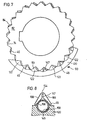
- FIG. 7 shows a side view of a clutch with only partially shown clutch ring gear 90
- clutch teeth 48 are shown, which can be varied in their flank angle. These each have a slot 147 extending from the tooth base to the vicinity of the tooth tip. The two flank parts of each tooth are therefore only connected in the area of the tooth tip, so that the flank angle is resiliently variable.
- FIG. 8 shows an embodiment variant with regard to the mounting of a coupling tooth 48 and the formation of the slot 147.
- the sleeve 120 has a semi-cylindrical recess 145.
- a cylindrical spring 156 is inserted, which is open at point 158, which points radially outwards.
- the coupling tooth 48 is seated on the spring 156 with its two flank parts 168, which delimit the slot 147 which widens downwards and which are connected to one another at the top (advantageously formed in one piece).
- the flank parts 168 of the coupling tooth 48 of FIG. 8 end at a distance from the sleeve 120, so that the coupling tooth 48 rides on the spring 156.
- An adaptation to the change of the flank angle is possible.
- the spring achieves an elastic spring loading of the clutch teeth in the direction of the virtual tooth gaps of the central wheel, so that a further embodiment of the separate resilient means is provided.
- Fig. 9 shows a coupling in side view with the possibility of increasing the torsional suspension of the coupling.
- Axial bores 73 are made in the body of the gearwheels and are open at 143 between the teeth between two teeth 46 and 74, e.g. through a crack.
- the teeth 46 and 74 are thus only connected to the body of the gearwheels via narrow webs 75. These webs can spring somewhat in the peripheral direction during operation, so that the torsional elasticity is increased.
- the gearwheels do not have any coupling hubs, but instead axially extending, rounded notches 126 are made in the shafts 31 to be coupled, into which the inwardly directed edges 34 of a zigzag plate 180, which in each case forms the gearwheel , intervene.
- These notches 126 must be sufficiently deep so that the zigzag plate 180 is not torn out of the notches 126 at the torques that occur.
- a safety slip clutch can be formed in this way, which separates the two coupled shafts when a certain torque is reached.
- the construction according to FIG. 10 has the advantage that the total effort for the coupling according to the invention is significantly reduced.
- the gear wheels are externally toothed and or the clutch ring gear is internally toothed
- the clutch ring gear is arranged within the gear wheels and its teeth are supported on an inner sleeve, so that the clutch teeth engage from the inside in the internally toothed gear wheels.
Claims (14)
Applications Claiming Priority (2)
| Application Number | Priority Date | Filing Date | Title |
|---|---|---|---|
| DE2742442 | 1977-09-21 | ||
| DE2742442A DE2742442C3 (de) | 1977-09-21 | 1977-09-21 | Elastische Kupplung |
Related Child Applications (1)
| Application Number | Title | Priority Date | Filing Date |
|---|---|---|---|
| EP80105184.8 Division-Into | 1980-08-30 |
Publications (2)
| Publication Number | Publication Date |
|---|---|
| EP0001268A1 EP0001268A1 (fr) | 1979-04-04 |
| EP0001268B1 true EP0001268B1 (fr) | 1981-05-20 |
Family
ID=6019502
Family Applications (3)
| Application Number | Title | Priority Date | Filing Date |
|---|---|---|---|
| EP80105184A Expired EP0025901B1 (fr) | 1977-09-21 | 1978-09-15 | Accouplement élastique |
| EP78100905A Expired EP0001268B1 (fr) | 1977-09-21 | 1978-09-15 | Accouplement élastique |
| EP83108915A Expired EP0103825B1 (fr) | 1977-09-21 | 1978-09-15 | Accouplement élastique |
Family Applications Before (1)
| Application Number | Title | Priority Date | Filing Date |
|---|---|---|---|
| EP80105184A Expired EP0025901B1 (fr) | 1977-09-21 | 1978-09-15 | Accouplement élastique |
Family Applications After (1)
| Application Number | Title | Priority Date | Filing Date |
|---|---|---|---|
| EP83108915A Expired EP0103825B1 (fr) | 1977-09-21 | 1978-09-15 | Accouplement élastique |
Country Status (16)
| Country | Link |
|---|---|
| EP (3) | EP0025901B1 (fr) |
| JP (1) | JPS5457054A (fr) |
| AR (1) | AR218335A1 (fr) |
| AT (1) | AT388034B (fr) |
| AU (1) | AU4007378A (fr) |
| BR (1) | BR7806186A (fr) |
| CS (1) | CS233706B2 (fr) |
| DD (1) | DD139368A5 (fr) |
| DE (1) | DE2742442C3 (fr) |
| DK (2) | DK154981C (fr) |
| ES (1) | ES245488Y (fr) |
| IN (1) | IN150784B (fr) |
| IT (1) | IT1105972B (fr) |
| PT (1) | PT68552A (fr) |
| SU (1) | SU784810A3 (fr) |
| ZA (1) | ZA785345B (fr) |
Families Citing this family (12)
| Publication number | Priority date | Publication date | Assignee | Title |
|---|---|---|---|---|
| DE2924935C3 (de) * | 1979-06-21 | 1982-02-11 | Balcke-Dürr AG, 4030 Ratingen | Elastische Wellenkupplung |
| DE3122965A1 (de) * | 1980-06-17 | 1982-03-18 | Balcke-Dürr AG, 4030 Ratingen | Elastische wellenkupplung |
| DE3036570C2 (de) * | 1980-09-27 | 1983-12-15 | Balcke-Dürr AG, 4030 Ratingen | Wellenkupplung |
| DE3211616C1 (de) * | 1982-03-30 | 1983-12-22 | Balcke-Dürr AG, 4030 Ratingen | Schaltgetriebe |
| DE3213846C2 (de) * | 1982-04-15 | 1985-01-03 | Balcke-Dürr AG, 4030 Ratingen | Elastische Kupplung |
| DE3304888C1 (de) * | 1983-02-12 | 1984-06-28 | Balcke-Dürr AG, 4030 Ratingen | Wellenkupplung |
| IT1227626B (it) * | 1988-11-28 | 1991-04-23 | Vectorpharma Int | Farmaci supportati aventi velocita' di dissoluzione aumentata e procedimento per la loro preparazione |
| FR2735822B1 (fr) * | 1995-06-21 | 1997-09-12 | Europ Propulsion | Accouplement sans jeu a entrainement instantane |
| DE102010055778A1 (de) * | 2010-12-23 | 2012-06-28 | Schottel Gmbh | Schiffsantrieb |
| DE102013218513A1 (de) | 2013-09-16 | 2015-03-19 | Schaeffler Technologies Gmbh & Co. Kg | Kupplung |
| DE202014007550U1 (de) * | 2014-09-12 | 2014-10-23 | Kwd Kupplungswerk Dresden Gmbh | Zahnkupplung |
| DE102014018842A1 (de) * | 2014-12-17 | 2016-06-23 | Süddeutsche Gelenkscheibenfabrik GmbH & Co. KG | Kupplungsvorrichtung und fadenverstärkte Gelenkvorrichtung |
Family Cites Families (14)
| Publication number | Priority date | Publication date | Assignee | Title |
|---|---|---|---|---|
| US1435141A (en) * | 1921-02-18 | 1922-11-07 | Smith | Flexible coupling device |
| GB438478A (en) * | 1934-08-28 | 1935-11-18 | Alois Wicha | Improvements in or relating to elastic couplings for shafts |
| US2701456A (en) * | 1950-02-07 | 1955-02-08 | Raymond G Brownstein | Flexible shaft coupling |
| US2737033A (en) * | 1951-04-09 | 1956-03-06 | Wilfrid H Bendall | Resilient gear couplings |
| FR1059414A (fr) * | 1952-07-02 | 1954-03-24 | Dispositif d'accouplement perfectionné | |
| GB827781A (en) * | 1957-05-24 | 1960-02-10 | Woods T B Sons Co | Improvements in flexible couplings for power transmission shafts |
| DE1149204B (de) * | 1958-09-11 | 1963-05-22 | Falk Corp | Elastische Wellenkupplung |
| US3473349A (en) * | 1966-07-27 | 1969-10-21 | Takanobu Tateyama | Elastic shaft coupling |
| DE1299949B (de) * | 1967-02-04 | 1969-07-24 | Zahnraederfabrik Bochum Alfons | Winkelbewegliche Kupplung |
| DE1283607B (de) * | 1967-10-21 | 1968-11-21 | Stoeckicht Alexander W | Zahnkupplung |
| US3704602A (en) * | 1970-12-01 | 1972-12-05 | Budd Co | Reinforced cast nylon coupling element |
| DE2135589B2 (de) * | 1971-07-16 | 1973-05-24 | Kupplungstechnik Gmbh, 4440 Rheine | Drehelastische kupplungshuelse fuer eine zahnkupplung |
| JPS5038670U (fr) * | 1973-07-30 | 1975-04-21 | ||
| US4047395A (en) * | 1976-10-04 | 1977-09-13 | Bendall Wilfrid H | Torsionally resilient gear coupling |
-
1977
- 1977-09-21 DE DE2742442A patent/DE2742442C3/de not_active Expired
-
1978
- 1978-09-11 CS CS785857A patent/CS233706B2/cs unknown
- 1978-09-14 PT PT68552A patent/PT68552A/pt unknown
- 1978-09-15 EP EP80105184A patent/EP0025901B1/fr not_active Expired
- 1978-09-15 EP EP78100905A patent/EP0001268B1/fr not_active Expired
- 1978-09-15 EP EP83108915A patent/EP0103825B1/fr not_active Expired
- 1978-09-18 AR AR273747A patent/AR218335A1/es active
- 1978-09-20 ZA ZA00785345A patent/ZA785345B/xx unknown
- 1978-09-20 SU SU782664399A patent/SU784810A3/ru active
- 1978-09-20 BR BR7806186A patent/BR7806186A/pt unknown
- 1978-09-20 ES ES1978245488U patent/ES245488Y/es not_active Expired
- 1978-09-20 DD DD78207953A patent/DD139368A5/xx unknown
- 1978-09-20 JP JP11574378A patent/JPS5457054A/ja active Pending
- 1978-09-20 DK DK417578A patent/DK154981C/da active
- 1978-09-21 AT AT0683078A patent/AT388034B/de not_active IP Right Cessation
- 1978-09-21 IT IT51172/78A patent/IT1105972B/it active
- 1978-09-21 AU AU40073/78A patent/AU4007378A/en active Pending
- 1978-11-21 IN IN1048/CAL/78A patent/IN150784B/en unknown
-
1987
- 1987-09-29 DK DK512587A patent/DK512587A/da unknown
Also Published As
| Publication number | Publication date |
|---|---|
| AU4007378A (en) | 1980-03-27 |
| BR7806186A (pt) | 1979-05-29 |
| IT7851172A0 (it) | 1978-09-21 |
| JPS5457054A (en) | 1979-05-08 |
| EP0103825A3 (en) | 1984-07-25 |
| EP0001268A1 (fr) | 1979-04-04 |
| EP0025901A3 (en) | 1981-05-06 |
| ES245488Y (es) | 1988-03-01 |
| IT1105972B (it) | 1985-11-11 |
| DK512587D0 (da) | 1987-09-29 |
| DE2742442C3 (de) | 1980-03-06 |
| DK512587A (da) | 1987-09-29 |
| ATA683078A (de) | 1988-09-15 |
| AR218335A1 (es) | 1980-05-30 |
| DK154981B (da) | 1989-01-16 |
| DK154981C (da) | 1989-06-05 |
| IN150784B (fr) | 1982-12-18 |
| EP0025901A2 (fr) | 1981-04-01 |
| PT68552A (de) | 1978-10-01 |
| DK417578A (da) | 1979-03-22 |
| ES245488U (es) | 1980-08-01 |
| DD139368A5 (de) | 1979-12-27 |
| CS233706B2 (en) | 1985-03-14 |
| DE2742442B2 (de) | 1979-07-19 |
| DE2742442A1 (de) | 1979-03-22 |
| ZA785345B (en) | 1979-08-29 |
| EP0103825A2 (fr) | 1984-03-28 |
| AT388034B (de) | 1989-04-25 |
| SU784810A3 (ru) | 1980-11-30 |
| EP0025901B1 (fr) | 1984-12-05 |
| EP0103825B1 (fr) | 1987-07-01 |
Similar Documents
| Publication | Publication Date | Title |
|---|---|---|
| DE3006331C3 (de) | Getriebe | |
| DE2206107C3 (de) | Selbstsperrendes Ausgleichsgetriebe | |
| DE2327566C3 (de) | Antriebsgruppe für ein Getriebe | |
| DE3206068C2 (de) | Kupplungsscheibe | |
| DE2508878C2 (de) | Torsionsdämpfende Kupplung, insbesondere für Reibscheiben von Kraftfahrzeugkupplungen | |
| DE2822686C2 (fr) | ||
| EP0253187A1 (fr) | Dispositif de synchronisation pour embrayages | |
| DE3324999C2 (fr) | ||
| DD297371A5 (de) | Reduktionsgetriebe fuer ein spielfreies gelenk, das vor allem zur verstellung von verschiedenen teilen eines kraftfahrzeugsitzes einsetzbar ist | |
| DE2829424A1 (de) | Rollenkette | |
| EP0001268B1 (fr) | Accouplement élastique | |
| DE1188890B (de) | Stirnradgetriebe | |
| DE10324224A1 (de) | Betätigungseinrichtung für ein Schaltgetriebe | |
| DE19702541B4 (de) | Zweiteiliges Gangrad für Schaltgetriebe | |
| DE19547980A1 (de) | Differentialgetriebe | |
| DE3317532A1 (de) | Torsionsdaempfungsvorrichtung, insbesondere reibungskupplung fuer kraftfahrzeuge | |
| DE2752445C2 (de) | Elastische Gelenkscheibe für Wellenkupplungen | |
| DE3714568C2 (fr) | ||
| DE3329259C2 (fr) | ||
| DE3525231C2 (fr) | ||
| DE2253041A1 (de) | Klauenkupplung | |
| DE2848288C2 (fr) | ||
| DE102008049978A1 (de) | Schalteinheit mit Kupplungskörper | |
| DE3121912C2 (de) | Energieführungskette | |
| DE2365067C2 (de) | Reibungskupplung |
Legal Events
| Date | Code | Title | Description |
|---|---|---|---|
| PUAI | Public reference made under article 153(3) epc to a published international application that has entered the european phase |
Free format text: ORIGINAL CODE: 0009012 |
|
| AK | Designated contracting states |
Designated state(s): BE CH FR GB LU NL SE |
|
| 17P | Request for examination filed | ||
| GRAA | (expected) grant |
Free format text: ORIGINAL CODE: 0009210 |
|
| AK | Designated contracting states |
Kind code of ref document: B1 Designated state(s): BE CH FR GB LU NL SE |
|
| PG25 | Lapsed in a contracting state [announced via postgrant information from national office to epo] |
Ref country code: LU Free format text: LAPSE BECAUSE OF NON-PAYMENT OF DUE FEES Effective date: 19810930 |
|
| PGFP | Annual fee paid to national office [announced via postgrant information from national office to epo] |
Ref country code: LU Payment date: 19830831 Year of fee payment: 6 |
|
| PGFP | Annual fee paid to national office [announced via postgrant information from national office to epo] |
Ref country code: CH Payment date: 19840830 Year of fee payment: 7 |
|
| PGFP | Annual fee paid to national office [announced via postgrant information from national office to epo] |
Ref country code: FR Payment date: 19840831 Year of fee payment: 7 |
|
| PGFP | Annual fee paid to national office [announced via postgrant information from national office to epo] |
Ref country code: SE Payment date: 19840930 Year of fee payment: 7 Ref country code: BE Payment date: 19840930 Year of fee payment: 7 |
|
| PGFP | Annual fee paid to national office [announced via postgrant information from national office to epo] |
Ref country code: NL Payment date: 19870930 Year of fee payment: 10 |
|
| PG25 | Lapsed in a contracting state [announced via postgrant information from national office to epo] |
Ref country code: GB Effective date: 19890915 |
|
| PG25 | Lapsed in a contracting state [announced via postgrant information from national office to epo] |
Ref country code: SE Effective date: 19890916 |
|
| PG25 | Lapsed in a contracting state [announced via postgrant information from national office to epo] |
Ref country code: CH Effective date: 19890930 Ref country code: BE Effective date: 19890930 |
|
| BERE | Be: lapsed |
Owner name: BALCKE-DURR A.G. Effective date: 19890930 |
|
| PG25 | Lapsed in a contracting state [announced via postgrant information from national office to epo] |
Ref country code: NL Effective date: 19900401 |
|
| GBPC | Gb: european patent ceased through non-payment of renewal fee | ||
| NLV4 | Nl: lapsed or anulled due to non-payment of the annual fee | ||
| PG25 | Lapsed in a contracting state [announced via postgrant information from national office to epo] |
Ref country code: FR Effective date: 19900531 |
|
| REG | Reference to a national code |
Ref country code: CH Ref legal event code: PL |
|
| REG | Reference to a national code |
Ref country code: FR Ref legal event code: ST |
|
| EUG | Se: european patent has lapsed |
Ref document number: 78100905.5 Effective date: 19900521 |
|
| PLBE | No opposition filed within time limit |
Free format text: ORIGINAL CODE: 0009261 |
|
| STAA | Information on the status of an ep patent application or granted ep patent |
Free format text: STATUS: NO OPPOSITION FILED WITHIN TIME LIMIT |