EP0510500B1 - Transportvorrichtung - Google Patents
Transportvorrichtung Download PDFInfo
- Publication number
- EP0510500B1 EP0510500B1 EP92106473A EP92106473A EP0510500B1 EP 0510500 B1 EP0510500 B1 EP 0510500B1 EP 92106473 A EP92106473 A EP 92106473A EP 92106473 A EP92106473 A EP 92106473A EP 0510500 B1 EP0510500 B1 EP 0510500B1
- Authority
- EP
- European Patent Office
- Prior art keywords
- chassis
- implement
- transport device
- connecting rod
- axle
- Prior art date
- Legal status (The legal status is an assumption and is not a legal conclusion. Google has not performed a legal analysis and makes no representation as to the accuracy of the status listed.)
- Expired - Lifetime
Links
- 230000008878 coupling Effects 0.000 claims description 7
- 238000010168 coupling process Methods 0.000 claims description 7
- 238000005859 coupling reaction Methods 0.000 claims description 7
- 230000015572 biosynthetic process Effects 0.000 claims 1
- 238000003306 harvesting Methods 0.000 description 6
- 238000010276 construction Methods 0.000 description 2
- 239000004459 forage Substances 0.000 description 2
- 238000004519 manufacturing process Methods 0.000 description 2
- 230000001419 dependent effect Effects 0.000 description 1
- 238000003971 tillage Methods 0.000 description 1
- 238000003466 welding Methods 0.000 description 1
Images
Classifications
-
- B—PERFORMING OPERATIONS; TRANSPORTING
- B60—VEHICLES IN GENERAL
- B60P—VEHICLES ADAPTED FOR LOAD TRANSPORTATION OR TO TRANSPORT, TO CARRY, OR TO COMPRISE SPECIAL LOADS OR OBJECTS
- B60P3/00—Vehicles adapted to transport, to carry or to comprise special loads or objects
- B60P3/40—Vehicles adapted to transport, to carry or to comprise special loads or objects for carrying long loads, e.g. with separate wheeled load supporting elements
-
- A—HUMAN NECESSITIES
- A01—AGRICULTURE; FORESTRY; ANIMAL HUSBANDRY; HUNTING; TRAPPING; FISHING
- A01B—SOIL WORKING IN AGRICULTURE OR FORESTRY; PARTS, DETAILS, OR ACCESSORIES OF AGRICULTURAL MACHINES OR IMPLEMENTS, IN GENERAL
- A01B73/00—Means or arrangements to facilitate transportation of agricultural machines or implements, e.g. folding frames to reduce overall width
- A01B73/005—Means or arrangements to facilitate transportation of agricultural machines or implements, e.g. folding frames to reduce overall width for endwise transportation, i.e. the direction of transport being substantially perpendicular to the direction of agricultural operation
-
- A—HUMAN NECESSITIES
- A01—AGRICULTURE; FORESTRY; ANIMAL HUSBANDRY; HUNTING; TRAPPING; FISHING
- A01D—HARVESTING; MOWING
- A01D90/00—Vehicles for carrying harvested crops with means for selfloading or unloading
- A01D90/12—Vehicles for carrying harvested crops with means for selfloading or unloading with additional devices or implements
-
- Y—GENERAL TAGGING OF NEW TECHNOLOGICAL DEVELOPMENTS; GENERAL TAGGING OF CROSS-SECTIONAL TECHNOLOGIES SPANNING OVER SEVERAL SECTIONS OF THE IPC; TECHNICAL SUBJECTS COVERED BY FORMER USPC CROSS-REFERENCE ART COLLECTIONS [XRACs] AND DIGESTS
- Y10—TECHNICAL SUBJECTS COVERED BY FORMER USPC
- Y10S—TECHNICAL SUBJECTS COVERED BY FORMER USPC CROSS-REFERENCE ART COLLECTIONS [XRACs] AND DIGESTS
- Y10S280/00—Land vehicles
- Y10S280/14—Tractor-trailer backing connections
Definitions
- the invention relates to a transport device for a working device with a connecting rod and a chassis, which are suitable for connection to a frame of the working device by means of a holder or on the underside thereof by means of connecting means.
- Transport devices are used to hold implements such as seeders, tillage tools, crop pickers, cutters, picking attachments and the like so that they can be towed behind a vehicle.
- implements such as seeders, tillage tools, crop pickers, cutters, picking attachments and the like.
- Most of the work tools are those that exceed the maximum permitted width for driving on public roads and therefore cannot be left across the vehicle in public transport.
- the vehicle is usually an agricultural tractor, a combine harvester, a forage harvester, a swath mower or the like, that is to say the vehicle to which the implement is connected during operation.
- one or two-axle carriages are used as such a transport device, which contain a longitudinal frame with contact surfaces and can be connected to a towing hitch provided on the vehicle.
- transport trolleys which extend over almost the entire length of the up to six meter wide / long implement, are relatively bulky, their manufacture is associated with correspondingly high manufacturing costs.
- a transport device known from DE-PS-26 44 360 provides for attaching an adapter to the front and rear of the implement, to which a chassis can be connected in each case.
- the chassis is attached to the vehicle with a drawbar.
- This transport device suffers from the disadvantage that it requires two chassis and the two chassis considerably lengthen the entire team, which is not desirable with regard to the transport journey.
- the brochure "Wetherell, Combine Head Transport” which shows all the features of the generic term, discloses a transport device for harvesting attachments of harvesting machines, which is composed of a drawbar and a chassis. While the drawbar can be attached to an end region of the harvesting attachment, the connection of the chassis to the underside of the latter is provided in the opposite end region, bolts being used for a quick connection in both cases.
- This transport device is disadvantageous in that when the harvesting device is transported in the state attached to the harvesting machine, the drawbar and the chassis have to be tracked separately on a delivery truck or the like.
- the object on which the invention is based is seen in creating a transport device which is still expedient even when the harvesting device is transported in the attached state.
- the front chassis can be omitted, which leads to a cost reduction.
- there is a reduction in the overall length of the team since one chassis can be dispensed with entirely and the other chassis is arranged below the implement.
- a simple way of attaching the connecting rod results from a telescopic connection, the connecting rod advantageously being able to be inserted as completely as possible into a tube, which can also be a part of the frame serving as a holder.
- the connecting rod is pushed so far into the tube or brought into cover with the holder that it does not protrude laterally over the implement, it can be accommodated there during operation.
- first and second connection means are provided which can be formed from hooks and bolts, from chains and receiving openings, from holders with openings and bolts or the like. These make it possible to attach the wheels to the implement for transport.
- the axle of the chassis need not be designed as a cylindrical rigid object; it can contain an axle beam and a connecting plate or the like.
- connection between the implement or its frame and the chassis is even more stable if positive Elements, such as a plate connected to the chassis or pegs fastened thereon, are provided which engage in corresponding openings which preferably result from the structure of the frame.
- positive Elements such as a plate connected to the chassis or pegs fastened thereon
- Such a connection is easy to establish since the implement is lowered from above onto the chassis and rests there captively due to its own weight. Even when shaken, the implement cannot separate from the chassis because it is held over the connection means.
- the chassis can be aligned very easily before a complete lowering of the implement for later connection and can be held in this position if it is secured against tilting about the wheel axis of rotation by means of a parking support which is preferably height-adjustable to adapt to the various conditions.
- the height-adjustable parking jack does not need to be turned up to an upper position, in which it can no longer come into contact with the floor if it is either easily removable, which, for. B. would be possible by means of a bolt connection, or if it can be pivoted into an inoperative position.
- the chassis can be pushed and positioned under the implement using this bracket. If the bracket can be released, it can be brought into a non-operating position with the parking support and placed on the implement, for example.
- a possibly to be considered tilting movement of the implement about its longitudinal axis is avoided if a holding device extends from the chassis to one side of the implement, which, for. B. on a reel, a guide rod or the like and, insofar as it is height adjustable, can adapt to the respective circumstances.
- An implement 10 shown in FIG. 1 is movably supported on the floor by means of a transport device 12 according to the invention.
- the implement 10 is a so-called pick-up that can be attached to the front of a forage harvester.
- the implement 10 is only shown in outline and contains at least one frame 14, a structure 16 and a crossbar 18, which normally serves as accident protection.
- Such an implement 10 has, for. B. a width of about 4 m and must be pulled behind a vehicle while driving on public roads.
- the frame 14 consists of a longitudinal tube 20, which extends over the entire length of the implement 10, and of transverse webs 22 welded onto it, which leave a distance from one another.
- the cross section of the longitudinal tube 20 is preferably polygonal, but it can also be round.
- the structure 16 which can contain a screw, tines and baffles, is welded or screwed onto the frame 14 and contains the functional elements of the implement 10.
- the crossbar 18 extends over the entire length of the structure 16 and is located at its lateral end with respect to the longitudinal axis of the implement 10.
- the transport device 12 is composed of a connecting rod 24 and a chassis 26, which are explained below.
- the connecting rod 24 is straight in this embodiment, but it could also be curved. Their length is chosen so that it extends from below the frame 14 to a towing hitch, not shown, on a vehicle, while leaving enough space between the implement 10 and the vehicle when turning leaves.
- a towing eye 28 is provided, which is preferably held within the circumference of the connecting rod 24.
- the connecting rod 24 is profiled such that it can be inserted into the longitudinal tube 20, which thus forms a holder 30 for the connecting rod 24 in its receiving region.
- At least one securing element 32 is provided, which extends through aligned openings in the holder 30 and the connecting rod 24 and thus establishes a positive connection between them. If the longitudinal tube 20 and thus also the holder 30 and at least the end region of the connecting rod 24 accommodated therein are of polygonal design, the connecting rod 24 lies in the holder 30 in a rotationally fixed manner, so that the securing elements 32 only prevent the connecting rod 24 from being pulled out of the holder 30 becomes.
- the connecting rod 24 could also be screwed laterally to the bracket 30.
- connecting rod 24 is rectilinear over its entire length, that is to say cylindrical, and the drawbar eye 28 does not protrude radially, and if there is also sufficient space in the holder 30, the connecting rod 24 can be completely inserted into the holder 30 and thus into the longitudinal tube 20 are so that it no longer protrudes over a side surface 34 of the implement 10.
- the chassis 26 is formed in particular by wheels 36, an axle 38 and, moreover, by a bracket 40, a parking support 42, a holding device 44 and first and second connecting means 46 and 48. Finally, it can contain a first and a second adapter, not shown.
- the wheels 36 are neither driven nor steerable and can rotate about an axis of rotation 54.
- Both single or double wheels 36 and two axles 38 with four or eight wheels 36 can be provided.
- the axle 38 rotatably receives the wheels 36 at its ends in a manner not shown and extends below and preferably over the entire width of the implement 10, so that the wheels 36 are located laterally therefrom.
- the axle 38 can consist of a simple rod or a welded assembly and only has the task of rotatably receiving the two wheels 36 and connecting them to the implement 10.
- the bracket 40 extends more or less in a horizontal plane and in this has the shape of a "U", the legs of which preferably engage releasably on the end of the axis 38.
- the web of the "U” runs across the implement 10 and can be used to maneuver the chassis 26 by hand.
- the legs of the bracket 40 are so long that the chassis 26 can be pushed by an operator under the implement 10 to the selected location.
- the bracket 40 can rigidly engage the axis 38 or be inserted and locked in sleeves there.
- the parking support 42 is connected in this embodiment of conventional, telescopic and variable construction and by welding or a screw connection in a manner not shown to the bracket 40 extending vertically.
- the parking support 42 can also be pivotably attached to the bracket 40 and pivoted into an operating and a non-operating position. Characterized in that the parking support 42 is located to the side of the axis of rotation 54, due to the weight of the bracket 40 and the parking support 42, the chassis 26 pivots counterclockwise with a view of the drawing and is supported against the floor on the parking support 42. The chassis 26 does not therefore tip over when it is brought into the correct position under the implement 10.
- the vertically extending holding device 44 On the axis 38, the vertically extending holding device 44 is also placed, which is also of conventional, telescopic and variable construction and carries at its upper end a fork 56 which can be brought into positive engagement with the crossbar 18. In this way, the implement 10 is supported by the fork 56 and the holding device 44 on the chassis 26 and cannot tilt due to its excess weight.
- the first connection means 46 are rigidly fastened in the form of horizontally extending bolts, in such a way that they can be overlapped from above by the second connection means 48, which are preferably designed as hooks or forks.
- the second connection means 48 can be provided on the crossbars 22 or the structure 16 at a suitable point. It is also dependent on the design of the implement 10 whether the connection means 46, 48 are provided on both sides of the implement 10 or only on one side. In any case, the chassis 26 is thereby captively connected to the implement 10.
- a first adapter can be placed on the top of the axis 38, ie welded or screwed, which fits exactly between two adjacent cross bars 22.
- the first adapter can be designed as a plate or as a frame with the dimensions predetermined by the spacing of the crossbars 22.
- a second adapter would be formed by the space between two adjacent crossbars 22, into which the first adapter fit exactly and could thus absorb the tensile forces between the implement 10 and the chassis 26.
- a coupling device 50 which is modeled on the holder 30, via which the connecting rod 24 can be connected can be attached to the axis 38.
- the transport device 12 uses the frame 14 of the implement 10 as a connection between its connecting rod 24 and its chassis 26 and can therefore do without its own longitudinal structure.
- the chassis 26 is positioned such that the connecting means 46, 48 and possibly the two adapters overlap and the chassis 26 is supported by the parking support 42 - unless a second person is available, which holds the chassis 26 in position.
- the implement 10 is then lowered until the positive connection between it and the chassis 26 is established.
- the connecting means 46, 48 are locked together and the parking support 42 is brought into its inoperative position.
- the connecting rod 24 is pulled out of the holder 30 and fixed by means of the securing element 32. If a support is attached to the connecting rod 24 or the implement 10, this is brought into its operating position until the implement 10 which is now mobile can be attached.
- the implement 10 is disconnected from the vehicle and the connecting rod 24 is connected to its hitch.
Landscapes
- Life Sciences & Earth Sciences (AREA)
- Engineering & Computer Science (AREA)
- Environmental Sciences (AREA)
- Mechanical Engineering (AREA)
- Health & Medical Sciences (AREA)
- Public Health (AREA)
- Transportation (AREA)
- Soil Sciences (AREA)
- Agricultural Machines (AREA)
- Harvester Elements (AREA)
- Electrical Discharge Machining, Electrochemical Machining, And Combined Machining (AREA)
- Refuse Collection And Transfer (AREA)
Description
- Die Erfindung betrifft eine Transportvorrichtung für ein Arbeitsgerät mit einer Verbindungsstange und einem Fahrgestell, die zum Anschluß an einen Rahmen des Arbeitsgeräts mittels einer Halterung bzw. an dessen Unterseite mittels Anschlußmitteln geeignet sind.
- Transportvorrichtungen werden dazu benutzt, Arbeitsgeräte wie etwa Sämaschinen, Bodenbearbeitungswerkzeuge, Erntegutaufnahmevorrichtungen, Schneidwerke, Pflückvorsätze und dergleichen so aufzunehmen, daß sie hinter einem Fahrzeug hergezogen werden können. Meist handelt es sich bei den Arbeitsgeräten um solche, die eine zur Fahrt auf öffentlichen Straßen höchstzulässige Breite überschreiten und deshalb im öffentlichen Verkehr nicht quer an dem Fahrzeug belassen werden können. Bei dem Fahrzeug handelt es sich normalerweise um einen Ackerschlepper, einen Mähdrescher, einen Feldhäcksler, einen Schwadmäher oder dergleichen, also um das Fahrzeug, an das das Arbeitsgerät während des Betriebs angeschlossen ist.
- Herkömmlich werden als eine derartige Transportvorrichtung ein- oder zweiachsige Wagen verwendet, die einen Längsrahmen mit Auflageflächen enthalten und mit einem an dem Fahrzeug vorgesehenen Zugmaul verbindbar sind. Abgesehen davon, daß derartige sich über nahezu die gesamte Länge des bis zu sechs Meter breiten/langen Arbeitsgeräts erstreckende Transportwagen relativ sperrig sind, ist ihre Herstellung mit entsprechend hohen Fertigungskosten verbunden.
- Demgegenüber sieht eine aus der DE-PS-26 44 360 bekannte Transportvorrichtung vor, an der Vorder- und der Rückseite des Arbeitsgeräts einen Adapter anzubringen, an den jeweils ein Fahrgestell angeschlossen werden kann. Das vordere Fahrgestell wird mit einer Deichsel an das Fahrzeug angehängt.
- Dieser Transportvorrichtung haftet der Nachteil an, daß sie zwei Fahrgestelle benötigt und die beiden Fahrgestelle das gesamte Gespann beträchtlich verlängern, was hinsichtlich der Transportfahrt nicht erwünscht ist.
- Der Prospekt "Wetherell, Combine Head Transport", welcher alle Merkmale des Oberbegriffs zeigt, offenbart eine Transportvorrichtung für Erntebergungsvorsätze von Erntemaschinen, die sich aus einer Deichsel und einem Fahrgestell zusammensetzt. Während die Deichsel an einen Endbereich des Erntebergungsvorsatzes angebracht werden kann, ist der Anschluß des Fahrgestells an dessen Unterseite im gegenüberliegenden Endbereich vorgesehen, wobei in beiden Fällen Bolzen für einen schnellen Anschluß verwendet werden.
- Diese Transportvorrichtung ist insofern nachteilig, als beim Transport der Erntebergungsvorrichtung im an die Erntemaschine angebauten Zustand die Deichsel und das Fahrgestell auf einem Lieferwagen oder dergl. getrennt nachgeführt werden müssen.
- Die der Erfindung zugrunde liegende Aufgabe wird darin gesehen, eine Transportvorrichtung zu schaffen, die auch dann noch zweckmäßig ist, wenn die Erntebergungsvorrichtung im angebauten Zustand transportiert wird.
- Diese Aufgabe ist erfindungsgemäß durch die Merkmale des Patentanspruchs 1 gelöst worden, wobei in den weiteren Patentansprüchen Merkmale aufgeführt sind, die die Lösung in vorteilhafter Weise weiterentwickeln.
- Auf diese Weise kann das vordere Fahrgestell entfallen, was eine Kostenreduzierung bewirkt. Außerdem tritt eine Verringerung der Gesamtlänge des Gespanns ein, da das eine Fahrgestell ganz entfallen kann und das andere Fahrgestell unterhalb des Arbeitsgeräts angeordnet ist. Darüberhinaus ist es möglich, die Verbindungsstange an dem Fahrgestell über eine Kupplungsvorrichtung anzuschließen, so daß dieses auch als Gespann ohne Arbeitsgerät auf dem Hof bewegt oder bei der Fahrt über das Feld hinter dem Fahrzeug hergezogen werden kann.
- Eine einfache Art der Anbringung der Verbindungsstange ergibt sich durch eine Teleskopverbindung, wobei vorteilhafterweise die Verbindungsstange in ein Rohr, das zugleich ein als Halterung dienender Teil des Rahmens sein kann, möglichst vollends einschiebbar ist.
- Wird die Verbindungsstange soweit in das Rohr hinein geschoben oder mit der Halterung in Deckung gebracht, daß sie seitlich nicht über das Arbeitsgerät übersteht, kann sie während des Betriebs dort untergebracht werden.
- Zum Erzielen einer sicheren Verbindung zwischen dem Fahrgestell und dem Arbeitsgerät sind erste und zweite Anschlußmittel vorgesehen, die aus Haken und Bolzen, aus Ketten und Aufnahmeöffnungen, aus Haltern mit Öffnungen und Riegeln oder dergleichen gebildet werden können. Diese ermöglichen es, die Räder an dem Arbeitsgerät für den Transport anzubringen. Selbstverständlich braucht die Achse des Fahrgestells nicht als ein zylindrischer starrer Gegenstand ausgeführt zu sein; sie kann einen Achskörper und eine Anschlußplatte oder dergleichen enthalten.
- Die Verbindung zwischen dem Arbeitsgerät bzw. dessen Rahmen und dem Fahrgestell wird noch stabiler, wenn formschlüssige Elemente, wie eine mit dem Fahrgestell verbundene Platte oder darauf befestigte Zapfen, vorgesehen sind, die in entsprechende, sich vorzugsweise aus der Struktur des Rahmens ergebende Öffnungen eingreifen. Eine derartige Verbindung ist leicht herzustellen, da das Arbeitsgerät von oben auf das Fahrgestell abgesenkt wird und dort aufgrund des Eigengewichts unverlierbar ruht. Auch bei Erschütterungen kann sich das Arbeitsgerät nicht von dem Fahrgestell trennen, weil es über die Anschlußmittel gehalten ist.
- Das Fahrgestell kann sehr einfach vor einem völligen Absenken des Arbeitsgeräts für den späteren Anschluß ausgerichtet und in dieser Stellung gehalten werden, wenn es gegen ein Kippen um die Raddrehachse mittels einer vorzugsweise zur Anpassung an die verschiedenen Verhältnisse höhenverstellbaren Abstellstütze gesichert wird.
- Die höhenverstellbare Abstellstütze braucht nicht jeweils in eine obere Stellung hochgedreht zu werden, in der sie nicht mehr mit dem Boden in Kontakt kommen kann, wenn sie entweder leicht demontierbar ist, was z. B. mittels einer Bolzenverbindung möglich wäre, oder wenn sie in eine Außerbetriebsstellung geschwenkt werden kann.
- Wird an dem Fahrgestell seitlich ein Bügel angebracht, an dem gleichzeitig die Abstellstütze befestigt ist, kann das Fahrgestell mittels dieses Bügels unter das Arbeitsgerät geschoben und positioniert werden. Ist der Bügel lösbar, kann er mit der Abstellstütze in eine Außerbetriebsstellung gebracht und beispielsweise auf das Arbeitsgerät aufgelegt werden.
- Eine gegebenenfalls zu beachtende Kippbewegung des Arbeitsgeräts um seine Längsachse wird vermieden, wenn sich von dem Fahrgestell zu einer Seite des Arbeitsgeräts eine Haltevorrichtung erstreckt, die z. B. an einer Haspel, einer Leitstange oder dergleichen angreift und, soweit sie höhenverstellbar ist, sich den jeweiligen Gegebenheiten anpassen kann.
- In der Zeichnung ist ein nachfolgend näher beschriebenes Ausführungsbeispiel der Erfindung dargestellt. Es zeigt:
- Fig. 1
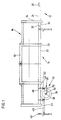
- ein Arbeitsgerät mit einer erfindungsgemäßen Transportvorrichtung in Seitenansicht und
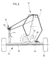
- Fig. 2
- das Arbeitsgerät mit der Transportvorrichtung in Vorderansicht.
- Ein in Figur 1 gezeigtes Arbeitsgerät 10 stützt sich mittels einer erfindungsgemäßen Transportvorrichtung 12 beweglich auf dem Boden ab.
- Bei dem Arbeitsgerät 10 handelt es sich in diesem Fall um eine sogenannte Pick-up, die an die Vorderseite eines Feldhäckslers angebaut werden kann. Das Arbeitsgerät 10 ist nur in Umrissen wiedergegeben und enthält wenigstens einen Rahmen 14, einen Aufbau 16 und eine Querstange 18, die normalerweise als Unfallschutz dient. Ein derartiges Arbeitsgerät 10 weist z. B. eine Breite von ca. 4 m auf und muß während der Fahrt auf öffentlichen Straßen hinter einem Fahrzeug hergezogen werden.
- Der Rahmen 14 besteht aus einem Längsrohr 20, das sich über die gesamte Länge des Arbeitsgeräts 10 erstreckt, und aus auf dieses aufgeschweißten Querstegen 22, die zueinander einen Abstand belassen. Der Querschnitt des Längsrohrs 20 ist vorzugsweise vieleckig, er kann aber auch rund sein.
- Der Aufbau 16, der eine Schnecke, Zinken und Leitbleche enthalten kann, ist auf den Rahmen 14 aufgeschweißt oder aufgeschraubt und enthält die funktionalen Elemente des Arbeitsgeräts 10.
- Die Querstange 18 erstreckt sich über die gesamte Länge des Aufbaus 16 und befindet sich an dessen seitlichem Abschluß mit Bezug auf die Längsachse des Arbeitsgeräts 10.
- Die Transportvorrichtung 12 setzt sich aus einer Verbindungsstange 24 und einem Fahrgestell 26 zusammen, die im folgenden erläutert werden.
- Die Verbindungsstange 24 ist in diesem Ausführungsbeispiel geradlinig ausgeführt, sie könnte aber ebenso gekrümmt sein. Ihre Länge ist so gewählt, daß sie sich von unterhalb des Rahmens 14 bis zu einem nicht gezeigten Zugmaul an einem Fahrzeug erstreckt und dabei genügend Freiraum zwischen dem Arbeitsgerät 10 und dem Fahrzeug beim Wenden beläßt. An dem vorderen Ende der Verbindungsstange 24 ist eine Zugöse 28 vorgesehen, die sich vorzugsweise innerhalb des Umfangs der Verbindungsstange 24 hält. An dem der Zugöse 28 gegenüberliegenden Endbereich ist die Verbindungsstange 24 derart profiliert, daß sie in das Längsrohr 20 einschiebbar ist, das in seinem Aufnahmebereich somit eine Halterung 30 für die Verbindungsstange 24 bildet. In dem Bereich der Halterung 30 ist mindestens ein Sicherungselement 32 vorgesehen, das sich durch fluchtende Öffnungen in der Halterung 30 und der Verbindungsstange 24 erstreckt und somit zwischen diesen eine formschlüssige Verbindung herstellt. Ist das Längsrohr 20 und somit auch die Halterung 30 und zumindest der darin aufgenommene Endbereich der Verbindungsstange 24 vieleckig ausgebildet, liegt die Verbindungsstange 24 in der Halterung 30 drehfest, so daß die Sicherungselemente 32 nur verhindern, daß die Verbindungsstange 24 aus der Halterung 30 heraus gezogen wird. Die Verbindungsstange 24 könnte aber ebenso seitlich an die Halterung 30 angeschraubt werden. Ist die Verbindungsstange 24 über ihre gesamte Länge geradlinig, d. h. zylindrisch ausgebildet und steht auch die Zugöse 28 nicht radial über, und ist darüberhinaus in der Halterung 30 genügend Freiraum vorhanden, kann die Verbindungsstange 24 vollkommen in die Halterung 30 und somit in das Längsrohr 20 eingeschoben werden, so daß sie nicht mehr über eine Seitenfläche 34 des Arbeitsgeräts 10 übersteht.
- Das Fahrgestell 26 wird insbesondere gebildet von Rädern 36, einer Achse 38 und darüberhinaus von einem Bügel 40, einer Abstellstütze 42, einer Haltevorrichtung 44 und ersten und zweiten Anschlußmitteln 46 und 48. Schließlich kann es ein erstes und ein zweites nicht gezeigtes Paßstück enthalten.
- Die Räder 36 sind weder angetrieben noch lenkbar und können um eine Drehachse 54 rotieren.
- Es können sowohl zwei einzelne oder doppelte Räder 36 als auch zwei Achsen 38 mit vier oder acht Rädern 36 vorgesehen werden.
- Die Achse 38 nimmt an ihren Enden auf nicht gezeigte Weise die Räder 36 drehbar auf und erstreckt sich unterhalb und vorzugsweise über die gesamte Breite des Arbeitsgeräts 10, so daß sich die Räder 36 seitlich davon befinden. Die Achse 38 kann aus einer einfachen Stange oder einem schweißzusammenbau bestehen und hat lediglich die Aufgabe, die beiden Räder 36 drehbar aufzunehmen und mit dem Arbeitsgerät 10 zu verbinden.
- Der Bügel 40 erstreckt sich mehr oder weniger in einer horizontalen Ebene und weist in dieser die Form eines "U" auf, dessen Schenkel endseitig an der Achse 38 vorzugsweise lösbar angreifen. Der Steg des "U" verläuft quer zu dem Arbeitsgerät 10 und kann dazu benutzt werden, das Fahrgestell 26 mit der Hand zu manövrieren. Die Schenkel des Bügels 40 sind so lang, dar das Fahrgestell 26 von einer Bedienungsperson unter das Arbeitsgerät 10 an die gewählte Stelle geschoben werden kann. Der Bügel 40 kann starr an der Achse 38 angreifen oder dort in Hülsen eingeschoben und arretiert werden.
- Die Abstellstütze 42 ist bei diesem Ausführungsbeispiel von herkömmlicher, teleskopartiger und längenveränderlicher Bauweise und durch Schweißen oder eine Schraub-Verbindung auf nicht gezeigte Weise an den Bügel 40 sich vertikal erstreckend angeschlossen. Die Abstellstütze 42 kann auch an dem Bügel 40 schwenkbar angebracht werden und in eine Betriebs- und eine Außerbetriebsstellung geschwenkt werden. Dadurch, daß sich die Abstellstütze 42 seitlich der Drehachse 54 befindet, schwenkt aufgrund des Gewichts des Bügels 40 und der Abstellstütze 42 das Fahrgestell 26 mit Blick auf die Zeichnung entgegen dem Uhrzeigerdrehsinn und stützt sich gegenüber dem Boden auf der Abstellstütze 42 ab. Das Fahrgestell 26 kippt also nicht um, wenn es unter das Arbeitsgerät 10 in die richtige Stellung gebracht ist.
- Auf die Achse 38 ist zudem die sich vertikal erstreckende Haltevorrichtung 44 aufgesetzt, die ebenfalls von herkömmlicher, teleskopartiger und längenveränderlicher Bauweise ist und an ihrem oberen Ende eine Gabel 56 trägt, die in Formschluß mit der Querstange 18 gebracht werden kann. Auf diese Weise stützt sich das Arbeitsgerät 10 über die Gabel 56 und die Haltevorrichtung 44 auf dem Fahrgestell 26 ab und kann nicht aufgrund ihres Übergewichts kippen.
- An der Achse 38 sind die ersten Anschlußmittel 46 in der Form sich horizontal erstreckender Bolzen starr befestigt, und zwar derart, daß sie von oben her von den zweiten Anschlußmitteln 48, die vorzugsweise als Haken oder Gabeln ausgebildet sind, übergriffen werden können. Sobald ein Formschluß zwischen den Anschlußmitteln 46, 48 erzielt ist, werden Stecker in die zweiten Anschlußmittel 48 eingeschoben, die ein Austreten der ersten Anschlußmittel 46 verhindern. Die zweiten Anschlußmittel 48 können an den Querstegen 22 oder dem Aufbau 16 an geeigneter Stelle vorgesehen werden. Es ist zudem abhängig von der Gestaltung des Arbeitsgeräts 10, ob die Anschlußmittel 46, 48 auf beiden Seiten des Arbeitsgeräts 10 vorgesehen werden oder nur auf einer Seite. Dadurch wird jedenfalls das Fahrgestell 26 unverlierbar mit dem Arbeitsgerät 10 verbunden.
- Schließlich kann auf die Oberseite der Achse 38 ein erstes Paßstück aufgesetzt, d. h. geschweißt oder geschraubt werden, das exakt zwischen zwei einander benachbarte Querstege 22 paßt. Das erste Paßstück kann als eine Platte oder als ein Rahmen mit den durch den Abstand der Querstege 22 vorgegebenen Maßen ausgebildet sein.
- Ein zweites Paßstück würde durch den Zwischenraum zwischen zwei benachbarten Querstegen 22 gebildet werden, in den das erste Paßstück genau paßte und somit die Zugkräfte zwischen dem Arbeitsgerät 10 und dem Fahrgestell 26 aufnehmen könnte.
- An der Achse 38 kann schließlich eine Kupplungsvorrichtung 50, die der Halterung 30 nachgebildet ist, angebracht sein, über die die Verbindungsstange 24 anschließbar ist.
- Nach alledem zeigt sich, daß die Transportvorrichtung 12 den Rahmen 14 des Arbeitsgeräts 10 als Verbindung zwischen ihrer Verbindungsstange 24 und ihrem Fahrgestell 26 nutzt und somit ohne einen eigenen Längsaufbau auskommen kann.
- Zum Aufsetzen des Arbeitsgeräts 10 auf die Transportvorrichtung 12 wird das Fahrgestell 26 so positioniert, daß sich die Anschlußmittel 46, 48 und gegebenenfalls die beiden Paßstücke decken und das Fahrgestell 26 mittels der Abstellstütze 42 abgestützt - es sei denn, eine zweite Person steht zur Verfügung, die das Fahrgestell 26 in seiner Stellung hält. Anschließend wird das Arbeitsgerät 10 abgesenkt, bis der Formschluß zwischen ihm und dem Fahrgestell 26 hergestellt ist. Dann werden die Anschlußmittel 46, 48 miteinander verriegelt und die Abstellstütze 42 in ihre Außerbetriebsstellung gebracht. Schließlich wird die Verbindungsstange 24 aus der Halterung 30 gezogen und mittels des Sicherungselements 32 festgelegt. Sofern eine Stütze an der Verbindungsstange 24 oder dem Arbeitsgerät 10 angebracht ist, wird diese bis zum Anhängen des nun fahrbaren Arbeitsgeräts 10 in ihre Betriebsstellung gebracht. Schließlich wird das Arbeitsgerät 10 von dem Fahrzeug getrennt und die Verbindungsstange 24 mit dessen Zugmaul verbunden.
Claims (10)
- Transportvorrichtung (12) für ein Arbeitsgerät (10) mit einer Verbindungsstange (24) und einem Fahrgestell (26), die zum Anschluß an einen Rahmen (14) des Arbeitsgeräts (10) mittels einer Halterung (30) bzw. an dessen Unterseite mittels Anschlußmitteln (46, 48) geeignet sind, dadurch gekennzeichnet, daß an dem Fahrgestell (26) eine Kupplungsvorrichtung (50) für den Anschluß der Verbindungsstange (24) vorgesehen ist.
- Transportvorrichtung nach Anspruch 1, gekennzeichnet durch eine Ausbildung der Verbindungsstange (24) als Deichsel einenends derart, daß sie in eine als Rohr ausgebildete Halterung (30) einschiebbar ist.
- Transportvorrichtung nach Anspruch 1 oder 2, gekennzeichnet durch eine Länge und Form der Verbindungsstange (24) derart, daß sie in der Halterung nicht oder nicht wesentlich über eine Seitenfläche (34) des Arbeitsgeräts (10) hinausragend aufgenommen werden kann.
- Transportvorrichtung nach einem oder mehreren der vorherigen Ansprüche, dadurch gekennzeichnet, daß das Fahrgestell (26) aus einer Räder (36) tragenden Achse (38) und mit der Achse (38) verbundenen ersten Anschlußmitteln (46) besteht, wobei die ersten Anschlußmittel (46) mit zweiten Anschlußmitteln (48) zusammenpassen und dem Anschluß der Achse (38) an den Rahmen (14) dienen.
- Transportvorrichtung nach Anspruch 4, dadurch gekennzeichnet, daß an der Achse (38) ein erstes Paßstück vorgesehen ist, das in ein zweites Paßstück an dem Arbeitsgerät (10) einfügbar ist.
- Transportvorrichtung nach einem oder mehreren der vorherigen Ansprüche, dadurch gekennzeichnet, daß das Fahrgestell (26) eine Abstellstütze (42) aufweist, die das Fahrgestell (26) seitlich des Drehpunkts der Räder (36) auf dem Boden abstützt.
- Transportvorrichtung nach Anspruch 6, dadurch gekennzeichnet, daß die Abstellstütze (42) in eine Außerbetriebsstellung bringbar ist.
- Transportvorrichtung nach Anspruch 6 oder 7, dadurch gekennzeichnet, daß die Abstellstütze (42) an einem sich von dem Fahrgestell (26) seitlich wegerstreckenden, vorzugsweise lösbaren Bügel (40) angebracht ist.
- Transportvorrichtung nach einem oder mehreren der vorherigen Ansprüche, dadurch gekennzeichnet, daß an dem Fahrgestell (26) eine Haltevorrichtung (44) vorgesehen ist, die im Seitenbereich des Arbeitsgeräts (10) angreift und dieses gegen ein Kippen um seine Längsachse sichert.
- Transportvorrichtung nach Anspruch 9, dadurch gekennzeichnet, daß die Haltevorrichtung (44) höhenverstellbar ist.
Applications Claiming Priority (2)
| Application Number | Priority Date | Filing Date | Title |
|---|---|---|---|
| DE4113299A DE4113299A1 (de) | 1991-04-24 | 1991-04-24 | Transportvorrichtung |
| DE4113299 | 1991-04-24 |
Publications (2)
| Publication Number | Publication Date |
|---|---|
| EP0510500A1 EP0510500A1 (de) | 1992-10-28 |
| EP0510500B1 true EP0510500B1 (de) | 1995-11-08 |
Family
ID=6430216
Family Applications (1)
| Application Number | Title | Priority Date | Filing Date |
|---|---|---|---|
| EP92106473A Expired - Lifetime EP0510500B1 (de) | 1991-04-24 | 1992-04-15 | Transportvorrichtung |
Country Status (5)
| Country | Link |
|---|---|
| US (1) | US5316338A (de) |
| EP (1) | EP0510500B1 (de) |
| AT (1) | ATE129846T1 (de) |
| DE (2) | DE4113299A1 (de) |
| IE (1) | IE921323A1 (de) |
Families Citing this family (6)
| Publication number | Priority date | Publication date | Assignee | Title |
|---|---|---|---|---|
| EP0820033B1 (de) * | 1996-07-19 | 2004-10-13 | Esselte | Banddruckgerät |
| FR2763782B1 (fr) * | 1997-05-30 | 1999-07-16 | Abc Equip Snc | Equipement ayant une forme prismatique allongee monte en travers sur une machine agricole et transformable pour son transport en long |
| FR2804576B1 (fr) * | 2000-02-08 | 2002-11-22 | Idass Sa | Dispositif de transport pour engins agricoles |
| DE10121039B4 (de) * | 2001-04-28 | 2014-08-21 | Deere & Company | Transportwagen für einen Erntebergungsvorsatz |
| WO2017139892A1 (en) | 2016-02-18 | 2017-08-24 | Seedmaster Manufacturing Ltd. | Implement operating apparatus |
| CA2964610C (en) | 2016-04-19 | 2022-08-09 | Seedmaster Manufacturing Ltd. | Agricultural implement and ramp attachment system |
Family Cites Families (12)
| Publication number | Priority date | Publication date | Assignee | Title |
|---|---|---|---|---|
| DE1090893B (de) * | 1957-01-23 | 1960-10-13 | Jakob Frueh | Landwirtschaftlicher Anhaengegeraetetraeger |
| FR1395536A (fr) * | 1963-03-26 | 1965-04-16 | Polyculteur attelé | |
| DE2204962A1 (de) * | 1972-02-03 | 1973-08-09 | Fries Gmbh Heinrich De | Transportvorrichtung fuer grossbehaelter |
| DD121469A1 (de) * | 1975-10-11 | 1976-08-05 | ||
| BE861976R (nl) * | 1977-02-04 | 1978-06-19 | Paul Geerinck | Aanhangwagentje |
| AT353106B (de) * | 1977-08-19 | 1979-10-25 | Bauer & Co Gmbh Reform Werke | Selbstfahrende, insbesondere landwirtschafliche arbeitsmaschine mit wechselaufbau |
| US4384445A (en) * | 1982-01-19 | 1983-05-24 | Sperry Corporation | Mechanism for releasably clamping a wheel assembly to a header cutterbar |
| US4385483A (en) * | 1982-01-19 | 1983-05-31 | Sperry Corporation | Transporting a crop harvesting header |
| DE3418721A1 (de) * | 1984-05-19 | 1985-11-21 | Agro-Industrie-Projekt GmbH, 7441 Schlaitdorf | Selbstfahrender geraetetraeger |
| DE8517625U1 (de) * | 1985-06-15 | 1987-01-22 | Reutter, Josef, 8701 Geroldshausen | Landwirtschaftliches Ackerbearbeitungsgerät |
| SU1579838A1 (ru) * | 1988-06-06 | 1990-07-23 | Предприятие П/Я В-8209 | Прицеп дл легкового автомобил |
| US5040825A (en) * | 1989-10-25 | 1991-08-20 | E-Z Trail, Inc. | Combine header transport |
-
1991
- 1991-04-24 DE DE4113299A patent/DE4113299A1/de active Granted
-
1992
- 1992-04-15 EP EP92106473A patent/EP0510500B1/de not_active Expired - Lifetime
- 1992-04-15 DE DE59204224T patent/DE59204224D1/de not_active Expired - Fee Related
- 1992-04-15 AT AT92106473T patent/ATE129846T1/de not_active IP Right Cessation
- 1992-04-23 IE IE132392A patent/IE921323A1/en not_active Application Discontinuation
- 1992-04-23 US US07/872,875 patent/US5316338A/en not_active Expired - Fee Related
Non-Patent Citations (1)
| Title |
|---|
| : Prospekt "Wetherell, Combine Head Transport" * |
Also Published As
| Publication number | Publication date |
|---|---|
| DE4113299A1 (de) | 1992-11-12 |
| DE59204224D1 (de) | 1995-12-14 |
| IE921323A1 (en) | 1992-11-04 |
| US5316338A (en) | 1994-05-31 |
| DE4113299C2 (de) | 1993-06-24 |
| EP0510500A1 (de) | 1992-10-28 |
| ATE129846T1 (de) | 1995-11-15 |
Similar Documents
| Publication | Publication Date | Title |
|---|---|---|
| EP0059409A2 (de) | Kraftfahrzeug, insbesondere Ackerschlepper | |
| DE2845801A1 (de) | Zugstangenvorrichtung fuer einen teilweise an einer zugeordneten zugmaschine abgestuetzten sattelhaenger | |
| DE3316128C2 (de) | ||
| DE2513413A1 (de) | Verfahren zur umwandlung eines geraeterahmens aus einem vorwaertsfahrenden erntebetriebszustand in einen seitwaertsfahrenden transportzustand | |
| EP0510500B1 (de) | Transportvorrichtung | |
| DE3632767A1 (de) | Kreiselheuwerbungsmaschine | |
| DE3883486T2 (de) | Anpassung der Anhängekupplung. | |
| DE1482111A1 (de) | Anbauvorrichtung fuer den Seitenanbau von landwirtschaftlichen Geraeten an einen Ackerschlepper | |
| EP0571794B1 (de) | Landwirtschaftliche Arbeitsmaschine, besonders Kreiselheuwender | |
| DE1966495C2 (de) | Schlepper für die Landwirtschaft | |
| DE4114681A1 (de) | Bodenbearbeitungsgeraet mit abrollenden werkzeugen | |
| DE3801895A1 (de) | Vorrichtung an der frontseite eines ackerschleppers zum anheben eines zusatzgewichttraegers in eine transportstellung | |
| DE948098C (de) | Dreipunktaufhaengung fuer schleppergezogene landwirtschaftliche Geraete mit zwei durch Seitenstreben am Schlepper abgestuetzten Unterlenkern und einem Oberlenker | |
| DE6939693U (de) | Geraeterahmen, insbesondere fuer bodenbearbeitungsgeraete | |
| DE8104256U1 (de) | Zusammengeschlossene geraetekombination fuer die landwirtschaft | |
| DE20012446U1 (de) | Landwirtschaftliche Maschine | |
| EP4118944B1 (de) | Dreipunktgetragenes, landwirtschaftliches anbaugerät | |
| DE2353172C3 (de) | Selbstfahrender Mähdrescher Deere & Co, Mohne, HL (VStAi.), Niederlassung Deere & Co. European Office, 6800 Mannheim | |
| DE6940840U (de) | Geraet, insbesondere zur bodenbearbeitung mit mindestens zwei tragrahmen | |
| DE884881C (de) | Mit einem mittleren, zugleich angetriebenen und lenkbaren Vorderrad ausgebildeter Dreirad-Schlepper, besonders fuer die Landwirtschaft | |
| DE3333915C2 (de) | ||
| DE3701877A1 (de) | Tragrahmen fuer landwirtschaftliche maschinen und einrichtungen | |
| EP2091315A1 (de) | Bodenbearbeitungsgerät mit grosser arbeitsbreite | |
| EP0094442A1 (de) | Bodenbearbeitungsmaschine für die Ankupplung an einen Schlepper | |
| DE1482176C (de) | Heuwerbungsmaschine |
Legal Events
| Date | Code | Title | Description |
|---|---|---|---|
| PUAI | Public reference made under article 153(3) epc to a published international application that has entered the european phase |
Free format text: ORIGINAL CODE: 0009012 |
|
| AK | Designated contracting states |
Kind code of ref document: A1 Designated state(s): AT BE CH DE FR GB IT LI NL |
|
| 17P | Request for examination filed |
Effective date: 19930424 |
|
| 17Q | First examination report despatched |
Effective date: 19940420 |
|
| GRAA | (expected) grant |
Free format text: ORIGINAL CODE: 0009210 |
|
| AK | Designated contracting states |
Kind code of ref document: B1 Designated state(s): AT BE CH DE FR GB IT LI NL |
|
| PG25 | Lapsed in a contracting state [announced via postgrant information from national office to epo] |
Ref country code: IT Free format text: LAPSE BECAUSE OF FAILURE TO SUBMIT A TRANSLATION OF THE DESCRIPTION OR TO PAY THE FEE WITHIN THE PRESCRIBED TIME-LIMIT;WARNING: LAPSES OF ITALIAN PATENTS WITH EFFECTIVE DATE BEFORE 2007 MAY HAVE OCCURRED AT ANY TIME BEFORE 2007. THE CORRECT EFFECTIVE DATE MAY BE DIFFERENT FROM THE ONE RECORDED. Effective date: 19951108 Ref country code: BE Effective date: 19951108 Ref country code: NL Free format text: LAPSE BECAUSE OF FAILURE TO SUBMIT A TRANSLATION OF THE DESCRIPTION OR TO PAY THE FEE WITHIN THE PRESCRIBED TIME-LIMIT Effective date: 19951108 |
|
| REF | Corresponds to: |
Ref document number: 129846 Country of ref document: AT Date of ref document: 19951115 Kind code of ref document: T |
|
| REF | Corresponds to: |
Ref document number: 59204224 Country of ref document: DE Date of ref document: 19951214 |
|
| GBT | Gb: translation of ep patent filed (gb section 77(6)(a)/1977) |
Effective date: 19951216 |
|
| ET | Fr: translation filed | ||
| NLV1 | Nl: lapsed or annulled due to failure to fulfill the requirements of art. 29p and 29m of the patents act | ||
| PG25 | Lapsed in a contracting state [announced via postgrant information from national office to epo] |
Ref country code: AT Effective date: 19960415 |
|
| PG25 | Lapsed in a contracting state [announced via postgrant information from national office to epo] |
Ref country code: CH Effective date: 19960430 Ref country code: LI Effective date: 19960430 |
|
| PLBE | No opposition filed within time limit |
Free format text: ORIGINAL CODE: 0009261 |
|
| STAA | Information on the status of an ep patent application or granted ep patent |
Free format text: STATUS: NO OPPOSITION FILED WITHIN TIME LIMIT |
|
| 26N | No opposition filed | ||
| REG | Reference to a national code |
Ref country code: CH Ref legal event code: PL |
|
| PGFP | Annual fee paid to national office [announced via postgrant information from national office to epo] |
Ref country code: GB Payment date: 19980323 Year of fee payment: 7 |
|
| PG25 | Lapsed in a contracting state [announced via postgrant information from national office to epo] |
Ref country code: GB Free format text: LAPSE BECAUSE OF NON-PAYMENT OF DUE FEES Effective date: 19990415 |
|
| PGFP | Annual fee paid to national office [announced via postgrant information from national office to epo] |
Ref country code: FR Payment date: 19990421 Year of fee payment: 8 |
|
| PGFP | Annual fee paid to national office [announced via postgrant information from national office to epo] |
Ref country code: DE Payment date: 19990616 Year of fee payment: 8 |
|
| GBPC | Gb: european patent ceased through non-payment of renewal fee |
Effective date: 19990415 |
|
| PG25 | Lapsed in a contracting state [announced via postgrant information from national office to epo] |
Ref country code: FR Free format text: LAPSE BECAUSE OF NON-PAYMENT OF DUE FEES Effective date: 20001229 |
|
| PG25 | Lapsed in a contracting state [announced via postgrant information from national office to epo] |
Ref country code: DE Free format text: LAPSE BECAUSE OF NON-PAYMENT OF DUE FEES Effective date: 20010201 |
|
| REG | Reference to a national code |
Ref country code: FR Ref legal event code: ST |