EP0504768A1 - Alpin-Skischuh mit einem auf der Hinterschale schwenkbaren Energieaufnahmebügel - Google Patents
Alpin-Skischuh mit einem auf der Hinterschale schwenkbaren Energieaufnahmebügel Download PDFInfo
- Publication number
- EP0504768A1 EP0504768A1 EP92104465A EP92104465A EP0504768A1 EP 0504768 A1 EP0504768 A1 EP 0504768A1 EP 92104465 A EP92104465 A EP 92104465A EP 92104465 A EP92104465 A EP 92104465A EP 0504768 A1 EP0504768 A1 EP 0504768A1
- Authority
- EP
- European Patent Office
- Prior art keywords
- stirrup
- rod
- rear part
- shell
- energy
- Prior art date
- Legal status (The legal status is an assumption and is not a legal conclusion. Google has not performed a legal analysis and makes no representation as to the accuracy of the status listed.)
- Withdrawn
Links
Images

Classifications
-
- A—HUMAN NECESSITIES
- A43—FOOTWEAR
- A43B—CHARACTERISTIC FEATURES OF FOOTWEAR; PARTS OF FOOTWEAR
- A43B5/00—Footwear for sporting purposes
- A43B5/04—Ski or like boots
- A43B5/0427—Ski or like boots characterised by type or construction details
- A43B5/048—Rear-entry skiboots
-
- A—HUMAN NECESSITIES
- A43—FOOTWEAR
- A43B—CHARACTERISTIC FEATURES OF FOOTWEAR; PARTS OF FOOTWEAR
- A43B5/00—Footwear for sporting purposes
- A43B5/04—Ski or like boots
- A43B5/0427—Ski or like boots characterised by type or construction details
- A43B5/0452—Adjustment of the forward inclination of the boot leg
- A43B5/0454—Adjustment of the forward inclination of the boot leg including flex control; Dampening means
- A43B5/0456—Adjustment of the forward inclination of the boot leg including flex control; Dampening means with the actuator being disposed at the rear side of the boot
Definitions
- the present invention relates to an alpine ski boot comprising a rigid shell of which a shell bottom is surmounted by a rod at least partially articulated on the latter around a transverse axis, which rod comprising at least a front part and a rear part , or rear cover, to allow the passage of the foot in the open position, a rod closing assembly forming a collar on the lower leg, being constituted by a clamping system at least partially surrounding the rod to be tensioned by a tensioning lever fixed on one of the constituent parts of said rod, means for controlling the flexion in amplitude and in forward force being produced on a rear part of the rod.
- Such a shoe is more particularly intended for footwear from above and shows anti-tilting means towards the rear produced in the form of a stop, disposed at the upper part of the heel.
- the adjustment of the front bending, in amplitude and in force, is in fact carried out by modification of the position of a cursor between the two lips of the rear notch, which cursor is adjustable in translation by screw means.
- the device for controlling and adjusting the front bending is here arranged on an element, in fact the rear extension of the bottom of the hull, obtained by molding in one piece, from a single material. It is therefore necessary to choose a material having both qualities of resistance with regard to the bottom of the shell and relative elasticity with regard to the extension of said bottom of the shell. This shows a difficulty in finding an ideal compromise to obtain a shell whose bottom is comfortable and the top elastic elastically reliable.
- an alpine ski boot comprising a rigid shell, the bottom of the shell of which is surmounted by a rod at least partially articulated on the latter around a transverse axis, and comprising at least a front part and a rear part, or rear cover, to allow the passage of the foot in the open position, a closure assembly of the rod forming a collar on the lower leg, being constituted by a clamping system at least partially surrounding the rod to be tensioned by a tensioning lever fixed on one of the front and rear parts constituting said rod, means for controlling the flexion in amplitude and in forward force being produced on the posterior part of the rod, characterized in that the means for controlling the flexion in amplitude, and in force are constituted by an energy stirrup integral with the rear part of the rod, interposed between the latter and the bottom of the shell and capable of being pivoted by said rear part relative to said bottom of the shell, in a movement directed in the postero-anterior
- the abutment zones cooperate with one another after free pivoting at a predetermined angle of the rod relative to the bottom of the shell, corresponding to the start of bending control of said rod, by reaction of said energy stirrup against the rear part of the rod.
- the flexibility of the energy stirrup is specifically controllable because, because of its independence, as regards the embodiment, it allows the use of specific materials preferably having very good qualities. 'elasticity. In addition, because of the small volume of this element, the choice of a more expensive material does not strike the cost price of the shoe.
- the energy stirrup pivots by driving the rear part of the rod in a postero-anterior movement or antero-posterior, according to a stroke of the stirrup stop zone, delimited respectively by the upper stop zone of the bottom of the shell acting in the postero-anterior direction, corresponding to the start of the flexion check, and by a zone fixed lower stop of the bottom of the shell corresponding to a lower posterior part of the heel, the fixed upper and lower stop zones of said bottom of the shell being angularly spaced at a predetermined angle, corresponding to a maximum opening angle of the rear part of the upper to allow putting on.
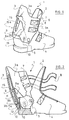
- the shoe shown in FIGS. 1 to 11 is of the rear entry type.
- the ski boot has a rod 1 consisting of a front part 2, a rear part 3, and a shell bottom 4 on which the rear part 3 of the rod 1 is connected by via a transverse axis 5 of articulation.
- the shoe shown also comprises several systems for tightening 6 and closing the rod 1 on the lower leg of the skier, each comprising, in a manner known per se, a tensioning lever 7 which subjects in tension a flexible link such as a cable loop 8 partially surrounding the front part 2 of the rod 1 to connect each tensioner 7 fixed on a wing 3a of the rear part 3, or rear cover, to anchor points (not shown) arranged on the other wing 3a of the same part 3, including in passing the front part 2, with a view to bringing them together.
- a tensioning lever 7 which subjects in tension a flexible link such as a cable loop 8 partially surrounding the front part 2 of the rod 1 to connect each tensioner 7 fixed on a wing 3a of the rear part 3, or rear cover, to anchor points (not shown) arranged on the other wing 3a of the same part 3, including in passing the front part 2, with a view to bringing them together.
- the shoe comprises means for controlling the flexion in amplitude and in forward force which are produced on the rear part 3 of the upper 1.
- these means consist of a shell-shaped energy stirrup 9, two lateral wings 9a of which at least partially overlap, in its rear part, the bottom of the shell 4, this stirrup 9 being itself capped by the lateral wings 3a of the rear part 3 of the rod 1 against which it is pressed integrally so as to be driven in pivoting relative to said bottom of the shell 4, in a postero-anterior or antero-posterior movement around two axes 10 set back behind the transverse articulation axis 5 of the rear part 3 of said rod 1 on the bottom of the shell 5.
- These axes 10 constitute connections between the wings 9a of the stirrup 9 and those 3a of the rear part 3 of the rod 1 thus secured to each other.
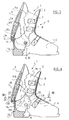
- the stop 11 then cooperates with a complementary stop 12 of the stirrup 9 after a free pivoting at a predetermined angle of the rod 1 and more precisely of its rear part 3 relative to the bottom of the shell 4.
- connection 10a between the stirrup 9 and the rear part 3 of the rod 1 which is movable in translation relative, at least, to the hinge pin 5 or to the stop 11, which are fixed in position on the bottom of the shell 4.
- the connection 10 is produced by means of a connection pin 10 which is fixedly positioned on the rear part 3 of the rod 1 and which cooperates with an oblong lumen 10b obtained in the energy bracket 9 and in which it can slide.
- the stops 12 and 11 are respectively produced in the lower part 9b of the energy stirrup 9 and in the upper posterior zone of the bottom of the shell 4 corresponding to the heel, and constitute projections approximately at right angles of complementary shapes but oriented in opposite directions head to tail, in order to be braced one on the other by mutual support.
- the energy stirrup is also capable of pivoting in an anteroposterior movement according to a stroke of the stop 12 of the stirrup 9 limited by a lower stop 13 of the bottom of the shell 4 corresponding to a lower posterior part of the heel, such as for example the upper edge of the sole of the shoe.
- This lower stop 13 is constituted by a horizontal shoulder obtained by molding with the bottom of the shell 4.
- the stops 11 and 13 respectively upper and lower of the bottom of the shell 4 thus defined are angularly spaced relative to the axis 5 at a certain angle, substantially defining the maximum opening angle of the rear part 3 of the rod 1 in view of footwear (fig. 2).
- a flange 14 is produced projecting outwards from the lower part 9b of said stirrup 9 constituting a support shoulder of the rear part 3 of the rod 1, during the opening of the latter.
- the energy stirrup 9 also has at its rear part, substantially in its median zone, a vertical notch 15 open in a flared manner upwards in this example, capable of being deformed by bringing together the edge lips 15a during a forward bending.
- the notch 15 is directed opposite the securing means 10 constituted by the axes of the stirrup 9 acting in the lower zone 3b of the rear part 3 of the rod 1.
- the stirrup 9 is then locked in pivoting forwards on the upper stop 11 of the bottom of the shell 4, and from this moment, the rear part 3 requests in bending before the stirrup 9 which, by a resistant effect, elastically deforms by simultaneous bringing together of the lips 15a of the notch 15 and buckling of these.
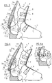
- this differs essentially from the previous ones in that the energy stirrup 9A pivots, relative to the bottom of the shell 4, around a connecting axis merging with the transverse axis 5 of articulation of the rear part 3 of the rod 1 corresponding substantially to the malleoli, this for the purpose of simplification of embodiment.
- the abutment of the energy stirrup 9B is formed by end edge portions 15c of each of its wings 16,17 capable of cooperating with the area of upper stop of the bottom of the shell 4, constituted in this case by two complementary shoulders 18 obtained on lateral wings 4a of the bottom of the shell 4 in correspondence with the edge portions 15 of the wings 16, 17 of the energy stirrup 9B.
- the energy stirrup 9B is secured to the rear part 3 of the rod 1, whether in an antero-posterior or postero-anterior direction, by the intermediate of a tenon 19 engaged in a corresponding notch 20 made in the lower zone of the rear part 3 of the rod 1.
- the energy stirrup 9C is secured to the rear part 3 of the rod 1 in the antero-posterior or postero-anterior directions by means of a means of effective assembly for example a rivet 21 connecting the lower zones 9b, 3b respectively of the stirrup 9C and of the rear part 3 of the rod 1.
- the energy stirrup 9 is obtained with a vertical notch 15 open upward to improve its flexibility and locate its deformable areas. It goes without saying that the stirrup can also be provided as a whole deformable; in this case, the deformable zones are simply located in a more or less random manner on the wings 9a and on the middle part of the energy stirrup 9.
- the energy stirrup 9 can also be provided to work more in bending in its lower part, unlike the previous embodiments; for this purpose, for example, as shown in FIG. 9, the energy stirrup 9D is secured to the rear part 3 of the rod 1 in its upper zone 9c and its vertical notch 15 is open downwards in its lower zone 9b.
- the abutment of the energy stirrup 9D is constituted by end edge portions 15d of each of its wings 16d, 17d which come to cooperate with the upper abutment zone of the bottom of the shell 4 such that two shoulders 18 obtained on the lateral wings 4a of the latter.
- the energy stirrup 9D can be linked to the rear part 3 of the rod 1 by means of different assembly means which can be, for example, a rivet 21 or a set of tenons 19-notch 20 as illustrated in Figures 6 and 7.
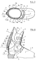
- the stirrup 9 and the rear part 3 of the rod 1 are connected to each other by means of a movable link 10a in which the axis 10 is adjustable on said rear part 3 in its relative position between the articulation axis 5 and the stop 11.
- the axis 10 is provided with a notched shoulder 25 intended to cooperate with a oblong slot 26 with notched edges obtained in the rear part 3 of the rod.
- This arrangement of the link 10a thus makes it possible to vary the ratio of the lever arms determined by the position of the axis 10 with the stop 11 and the articulation axis 5 and, intrinsically, the amplitude of the pivoting imposed on the stirrup 9 by the rod 1, when the rear part 3 of the latter bends in the direction F1. It results from such an embodiment that the control of flexion can, from a stirrup 9 and a rear part 3 of given rod, be modifiable in amplitude and in effort.
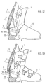
- the shoe shown by way of example is of the rear entry type: it is obvious that the invention is not limited to a such a shoe and may relate to a shoe of the "mixed entry” type, FIG. 12, or of the "top entry” type, FIG. 13.
- the stirrup 9 is mounted on the rear part 3 of the upper 1 in the same way as in the previous examples and thus makes it possible to control in amplitude and in effort the bending of said rear part 3 of the rod towards the front. It is obvious that the energy stirrup 9 can, according to the desired behavior of the shoe, alone provide control of the flexion of the upper 1 of the shoe.
- stirrup 9 can be associated with another device or means for controlling flexion, of a known type, which acts at the level of the front part 2 of the rod 1 relative to the bottom of the shell 4; the efforts resisting the bending of the rod 1 towards the front are then distributed between the rear part 3 of the latter which tends to pull the lower leg of the skier towards the rear, and between the front part 2 which tends to push back said lower leg.
- the energy stirrup 9, 9A, 9B, 9C can be obtained by molding plastic material in a single piece.
Landscapes
- Health & Medical Sciences (AREA)
- General Health & Medical Sciences (AREA)
- Physical Education & Sports Medicine (AREA)
- Footwear And Its Accessory, Manufacturing Method And Apparatuses (AREA)
Applications Claiming Priority (2)
| Application Number | Priority Date | Filing Date | Title |
|---|---|---|---|
| FR9103668A FR2674106A1 (fr) | 1991-03-21 | 1991-03-21 | Chaussure de ski alpin a etrier d'energie articule sur le capot arriere. |
| FR9103668 | 1991-03-21 |
Publications (1)
| Publication Number | Publication Date |
|---|---|
| EP0504768A1 true EP0504768A1 (de) | 1992-09-23 |
Family
ID=9411150
Family Applications (1)
| Application Number | Title | Priority Date | Filing Date |
|---|---|---|---|
| EP92104465A Withdrawn EP0504768A1 (de) | 1991-03-21 | 1992-03-16 | Alpin-Skischuh mit einem auf der Hinterschale schwenkbaren Energieaufnahmebügel |
Country Status (4)
| Country | Link |
|---|---|
| US (1) | US5353528A (de) |
| EP (1) | EP0504768A1 (de) |
| JP (1) | JPH0576401A (de) |
| FR (1) | FR2674106A1 (de) |
Cited By (2)
| Publication number | Priority date | Publication date | Assignee | Title |
|---|---|---|---|---|
| AT402363B (de) * | 1993-08-19 | 1997-04-25 | Koeflach Sportgeraete Gmbh | Ski-, berg-, eislauf- oder rollschuh mit einer kunststoffschale sowie verfahren zur herstellung desselben |
| FR2758092A1 (fr) * | 1997-01-08 | 1998-07-10 | Burton Corp | Ensemble de fixation pour monoski |
Families Citing this family (9)
| Publication number | Priority date | Publication date | Assignee | Title |
|---|---|---|---|---|
| FR2733125B1 (fr) * | 1995-04-19 | 1997-07-04 | Salomon Sa | Chaussure avec controle de flexion de la tige |
| FR2740011B1 (fr) * | 1995-10-20 | 1997-12-12 | Salomon Sa | Chaussure a tige ajustable |
| FR2752147B1 (fr) * | 1996-08-06 | 1998-10-09 | Salomon Sa | Chaussure de sport |
| FR2767034B1 (fr) * | 1997-08-05 | 1999-09-10 | Salomon Sa | Chaussure de sport a flexibilite determinee |
| DE10234913B4 (de) | 2002-07-31 | 2005-11-10 | Adidas International Marketing B.V. | Schuhsohle |
| US7401419B2 (en) | 2002-07-31 | 2008-07-22 | Adidas International Marketing B.V, | Structural element for a shoe sole |
| DE102005006267B3 (de) | 2005-02-11 | 2006-03-16 | Adidas International Marketing B.V. | Schuhsohle und Schuh |
| DE102006015649B4 (de) | 2006-04-04 | 2008-02-28 | Adidas International Marketing B.V. | Schuh |
| EP2572599B1 (de) * | 2011-09-26 | 2015-04-22 | Rossignol Lange S.R.L. | Schale für Skischuh mit Spoiler |
Citations (4)
| Publication number | Priority date | Publication date | Assignee | Title |
|---|---|---|---|---|
| DE3530243A1 (de) * | 1985-08-23 | 1987-03-05 | Josef Lederer | Skistiefel |
| FR2619684A1 (fr) * | 1987-09-02 | 1989-03-03 | Salomon Sa | Chaussure de ski alpin a tige articulee |
| EP0350023A2 (de) * | 1988-07-07 | 1990-01-10 | TECNICA SpA | Vorrichtung zum Einstellen der Biegsamkeit von Schischuhen |
| EP0380444A1 (de) * | 1989-01-27 | 1990-08-01 | Lange International S.A. | Skischuh |
Family Cites Families (17)
| Publication number | Priority date | Publication date | Assignee | Title |
|---|---|---|---|---|
| GB836755A (en) * | 1957-12-09 | 1960-06-09 | Goodrich Co B F | Improvements in and relating to polymers |
| US3521385A (en) * | 1968-05-02 | 1970-07-21 | Melvin W Dalebout | Ski boot |
| CH512204A (de) * | 1969-12-23 | 1971-09-15 | Rieker & Co Dr Justus | Skistiefel |
| US3619914A (en) * | 1970-02-13 | 1971-11-16 | Lange & Co | Boot tensioning device |
| US3713231A (en) * | 1970-06-11 | 1973-01-30 | Hope Kk | Ski boot |
| CH587668A5 (de) * | 1974-11-28 | 1977-05-13 | Salomon & Fils F | |
| FR2305948A1 (fr) * | 1975-04-03 | 1976-10-29 | Trappeur | Chaussures de ski perfectionnees |
| FR2330345A1 (fr) * | 1975-11-04 | 1977-06-03 | Trappeur | Chaussure de ski perfectionnee |
| US4078322A (en) * | 1976-08-04 | 1978-03-14 | Engineered Sports Products, Inc. | Ski boot |
| US4095356A (en) * | 1976-10-15 | 1978-06-20 | Scott Usa, Inc. | Boot with pivoted upper |
| FR2454767A2 (fr) * | 1978-06-16 | 1980-11-21 | Salomon & Fils F | Chaussure de ski |
| US4565017A (en) * | 1984-09-28 | 1986-01-21 | Ottieri Enterprises | Ski boot |
| US4691454A (en) * | 1984-09-28 | 1987-09-08 | Ottieri Enterprises | Ski boot closure system |
| US4669202A (en) * | 1984-09-28 | 1987-06-02 | Ottieri Enterprises | Ski boot |
| IT1214138B (it) * | 1987-09-15 | 1990-01-10 | Nordica Spa | Dispositivo di bloccaggio del tallone, particolarmente per scarponi da sci. |
| EP0374056B1 (de) * | 1988-12-13 | 1994-06-01 | Salomon S.A. | Alpinskischuh der Bauart mit rückwärtigem Einstieg |
| FR2652240B1 (fr) * | 1989-09-28 | 1992-01-24 | Salomon Sa | Dispositif de reglage de la position d'un palonnier par rapport a la tige d'une chaussure. |
-
1991
- 1991-03-21 FR FR9103668A patent/FR2674106A1/fr active Granted
-
1992
- 1992-03-16 EP EP92104465A patent/EP0504768A1/de not_active Withdrawn
- 1992-03-17 JP JP4060433A patent/JPH0576401A/ja not_active Withdrawn
-
1993
- 1993-11-12 US US08/150,797 patent/US5353528A/en not_active Expired - Fee Related
Patent Citations (4)
| Publication number | Priority date | Publication date | Assignee | Title |
|---|---|---|---|---|
| DE3530243A1 (de) * | 1985-08-23 | 1987-03-05 | Josef Lederer | Skistiefel |
| FR2619684A1 (fr) * | 1987-09-02 | 1989-03-03 | Salomon Sa | Chaussure de ski alpin a tige articulee |
| EP0350023A2 (de) * | 1988-07-07 | 1990-01-10 | TECNICA SpA | Vorrichtung zum Einstellen der Biegsamkeit von Schischuhen |
| EP0380444A1 (de) * | 1989-01-27 | 1990-08-01 | Lange International S.A. | Skischuh |
Cited By (4)
| Publication number | Priority date | Publication date | Assignee | Title |
|---|---|---|---|---|
| AT402363B (de) * | 1993-08-19 | 1997-04-25 | Koeflach Sportgeraete Gmbh | Ski-, berg-, eislauf- oder rollschuh mit einer kunststoffschale sowie verfahren zur herstellung desselben |
| FR2758092A1 (fr) * | 1997-01-08 | 1998-07-10 | Burton Corp | Ensemble de fixation pour monoski |
| US6027136A (en) * | 1997-01-08 | 2000-02-22 | The Burton Corporation | System for preventing toe-edge travel of a hi-back |
| US6283495B1 (en) | 1997-01-08 | 2001-09-04 | The Burton Corporation | System for preventing toe-edge travel of a hi-back |
Also Published As
| Publication number | Publication date |
|---|---|
| FR2674106B1 (de) | 1995-02-10 |
| US5353528A (en) | 1994-10-11 |
| FR2674106A1 (fr) | 1992-09-25 |
| JPH0576401A (ja) | 1993-03-30 |
Similar Documents
| Publication | Publication Date | Title |
|---|---|---|
| EP0644730B1 (de) | Ski- oder schlittschuh | |
| EP0278281B1 (de) | Schischuh | |
| EP0486940B1 (de) | Alpinskischuh | |
| FR2640516A1 (fr) | Fixation de securite pour ski destinee a maintenir, de facon declenchable, l'avant d'une chaussure montee sur le ski | |
| FR2583272A1 (fr) | Chaussure de ski alpin | |
| EP0895727B1 (de) | Sportschuh mit bestimmter Biegsamkeit | |
| EP0504768A1 (de) | Alpin-Skischuh mit einem auf der Hinterschale schwenkbaren Energieaufnahmebügel | |
| CH663329A5 (fr) | Chaussure de ski. | |
| EP0521282A1 (de) | Skischuh mit Schwenksperre für den Schaft | |
| FR2617380A1 (fr) | Chaussure comportant un dispositif de reglage de l'inclinaison de l'axe d'articulation de la tige sur la coque | |
| FR2722421A1 (fr) | Element de fixation de ski alpin | |
| FR2672189A1 (fr) | Chaussure de ski a capot arriere articule sur le bras de coque. | |
| EP0634197B1 (de) | Bindungselement für einen alpinen Ski | |
| EP0504769B1 (de) | Alpin-Skischuh mit einer am Schalenunterteil schwenkbaren Energiedämpfungsklappe | |
| EP0699399A1 (de) | Schischuh | |
| EP0638341B1 (de) | Ski-Stopper | |
| EP1358916A1 (de) | Schuh für Betreiben eines Gleitsport oder Snowboardbindung mit Klemmlappen | |
| CH667977A5 (fr) | Chaussure de ski a entree arriere. | |
| EP0664968A1 (de) | Schischuh mit angelenkten Schaftvorderteil | |
| EP0648439B1 (de) | Schischuh | |
| EP0193686A1 (de) | Rückhaltevorrichtung für einen Schuh auf einem Ski | |
| EP0712586A1 (de) | Schischuh | |
| FR2583271A1 (fr) | Chaussure de ski alpin | |
| EP0436444B1 (de) | Skischuh aus Kunststoff | |
| FR2617381A1 (fr) | Chaussure, notamment de ski alpin a tige articulee |
Legal Events
| Date | Code | Title | Description |
|---|---|---|---|
| PUAI | Public reference made under article 153(3) epc to a published international application that has entered the european phase |
Free format text: ORIGINAL CODE: 0009012 |
|
| AK | Designated contracting states |
Kind code of ref document: A1 Designated state(s): CH DE FR IT LI |
|
| 17P | Request for examination filed |
Effective date: 19930311 |
|
| 17Q | First examination report despatched |
Effective date: 19930803 |
|
| STAA | Information on the status of an ep patent application or granted ep patent |
Free format text: STATUS: THE APPLICATION IS DEEMED TO BE WITHDRAWN |
|
| 18D | Application deemed to be withdrawn |
Effective date: 19950912 |