EP0504768A1 - Alpine ski boot having an articulated movement clamp on the rear shell - Google Patents
Alpine ski boot having an articulated movement clamp on the rear shell Download PDFInfo
- Publication number
- EP0504768A1 EP0504768A1 EP92104465A EP92104465A EP0504768A1 EP 0504768 A1 EP0504768 A1 EP 0504768A1 EP 92104465 A EP92104465 A EP 92104465A EP 92104465 A EP92104465 A EP 92104465A EP 0504768 A1 EP0504768 A1 EP 0504768A1
- Authority
- EP
- European Patent Office
- Prior art keywords
- stirrup
- rod
- rear part
- shell
- energy
- Prior art date
- Legal status (The legal status is an assumption and is not a legal conclusion. Google has not performed a legal analysis and makes no representation as to the accuracy of the status listed.)
- Withdrawn
Links
Images

Classifications
-
- A—HUMAN NECESSITIES
- A43—FOOTWEAR
- A43B—CHARACTERISTIC FEATURES OF FOOTWEAR; PARTS OF FOOTWEAR
- A43B5/00—Footwear for sporting purposes
- A43B5/04—Ski or like boots
- A43B5/0427—Ski or like boots characterised by type or construction details
- A43B5/048—Rear-entry skiboots
-
- A—HUMAN NECESSITIES
- A43—FOOTWEAR
- A43B—CHARACTERISTIC FEATURES OF FOOTWEAR; PARTS OF FOOTWEAR
- A43B5/00—Footwear for sporting purposes
- A43B5/04—Ski or like boots
- A43B5/0427—Ski or like boots characterised by type or construction details
- A43B5/0452—Adjustment of the forward inclination of the boot leg
- A43B5/0454—Adjustment of the forward inclination of the boot leg including flex control; Dampening means
- A43B5/0456—Adjustment of the forward inclination of the boot leg including flex control; Dampening means with the actuator being disposed at the rear side of the boot
Landscapes
- Health & Medical Sciences (AREA)
- General Health & Medical Sciences (AREA)
- Physical Education & Sports Medicine (AREA)
- Footwear And Its Accessory, Manufacturing Method And Apparatuses (AREA)
Abstract
Description
La présente invention concerne une chaussure de ski alpin comportant une coque rigide dont un bas de coque est surmonté d'une tige au moins partiellement articulée sur ce dernier autour d'un axe transversal, laquelle tige comprenant au moins une partie antérieure et une partie postérieure, ou capot arrière, pour permettre le passage du pied en position d'ouverture, un ensemble de fermeture de la tige formant collier sur le bas de jambe, étant constitué par un système de serrage entourant au moins partiellement la tige pour être mis en tension par un levier tendeur fixé sur l'une des parties constitutives de ladite tige, des moyens de contrôle de la flexion en amplitude et en effort vers l'avant étant réalisés sur une partie arrière de la tige.The present invention relates to an alpine ski boot comprising a rigid shell of which a shell bottom is surmounted by a rod at least partially articulated on the latter around a transverse axis, which rod comprising at least a front part and a rear part , or rear cover, to allow the passage of the foot in the open position, a rod closing assembly forming a collar on the lower leg, being constituted by a clamping system at least partially surrounding the rod to be tensioned by a tensioning lever fixed on one of the constituent parts of said rod, means for controlling the flexion in amplitude and in forward force being produced on a rear part of the rod.
Différentes solutions ont déjà été proposées afin de réaliser de tels moyens de contrôle de la flexion.Various solutions have already been proposed in order to achieve such means of controlling flexion.
Notamment dans la demande de brevet européen no 350 023, il est décrit une chaussure de ski dont le bas de coque comporte une extension constituant deux parties symétriques séparées par une entaille à l'arrière définissant deux lèvres, alors qu'à sa partie avant l'extension est constituée par deux pans se croisant par chevauchement.In particular in European patent application No. 350 023 there is disclosed a ski boot whose shell base comprises an extension forming two symmetrical parts separated by a notch at the back defining two lips, whereas its front portion the extension is formed by two sections crossing each other by overlapping.
Une telle chaussure est plus particulièrement destinée au chaussage par le dessus et montre des moyens d'anti-basculement vers l'arrière réalisés sous forme d'une butée, disposée à la partie supérieure du talon.Such a shoe is more particularly intended for footwear from above and shows anti-tilting means towards the rear produced in the form of a stop, disposed at the upper part of the heel.
Le réglage de la flexion avant, en amplitude et en effort, est en fait réalisée par modification de la position d'un curseur entre les deux lèvres de l'entaille arrière, lequel curseur est réglable en translation par des moyens à vis.The adjustment of the front bending, in amplitude and in force, is in fact carried out by modification of the position of a cursor between the two lips of the rear notch, which cursor is adjustable in translation by screw means.
Le dispositif de contrôle et de réglage de la flexion avant est ici disposé sur un élément, en fait l'extension arrière du bas de coque, obtenu de moulage d'une seule pièce, à partir d'un matériau unique. Il y a donc nécessité de choisir un matériau ayant à la fois des qualités de résistance pour ce qui concerne le bas de coque et d'élasticité relative en ce qui concerne l'extension dudit bas de coque. Il ressort de cela une difficulté à trouver un compromis idéal pour obtenir une coque dont le bas soit confortable et le haut fiable élastiquement.The device for controlling and adjusting the front bending is here arranged on an element, in fact the rear extension of the bottom of the hull, obtained by molding in one piece, from a single material. It is therefore necessary to choose a material having both qualities of resistance with regard to the bottom of the shell and relative elasticity with regard to the extension of said bottom of the shell. This shows a difficulty in finding an ideal compromise to obtain a shell whose bottom is comfortable and the top elastic elastically reliable.
De plus, une telle technique entraîne également des difficultés de démoulage dues essentiellement à la hauteur des extensions et au chevauchement à obtenir à la partie avant.In addition, such a technique also leads to demoulding difficulties due essentially to the height of the extensions and the overlap to be obtained at the front part.
Par ailleurs, ce type de chaussure, du fait de cette construction est difficile à chausser car l'on doit écarter toute sa partie supérieure pour introduire le pied, à plus forte raison du fait que le collier est bloqué dans sa position antéropostérieure, comme évoqué ci-dessus.Furthermore, this type of shoe, because of this construction is difficult to put on because one has to spread all of its upper part to introduce the foot, all the more so because the collar is locked in its anteroposterior position, as mentioned. above.
Pour remédier au manque d'ouverture arrière de la chaussure, il est également connu un brevet suisse no 375 526 proposant une chaussure de ski alpin à chaussage par l'arrière, et dans laquelle le débattement angulaire d'un-capot arrière, l'un des éléments constitutifs de la tige, est limité vers l'avant par un élément de retenue réalisé en saillie à la partie inférieure dudit capot arrière, et coopère avec un rebord du talon sur le bas de coque.To remedy the lack of rear opening of the boot, it is also known a Swiss patent n o 375 526 proposing an alpine ski boot with rear boot, and in which the angular movement of a rear hood, the 'one of the constituent elements of the upper, is limited towards the front by a retaining element projecting from the lower part of said rear cover, and cooperates with a rim of the heel on the bottom of the shell.
On comprend aisément que de tels moyens limiteurs de la flexion ne sauraient pas être précis car ils la limitent globalement, sans contrôle spécifique vers l'avant.It is easily understood that such bending limiting means cannot be precise because they limit it overall, without specific control forwards.
La présente invention a pour but de remédier à ces inconvénients et concerne à cet effet une chaussure de ski alpin comportant une coque rigide dont un bas de coque est surmonté d'une tige au moins partiellement articulée sur ce dernier autour d'un axe transversal, et comprenant au moins une partie antérieure et une partie postérieure, ou capot arrière, pour permettre le passage du pied en position d'ouverture, un ensemble de fermeture de la tige formant collier sur le bas de jambe, étant constitué par un système de serrage entourant au moins partiellement la tige pour être mis en tension par un levier tendeur fixé sur l'une des parties antérieure et postérieure constitutives de ladite tige, des moyens de contrôle de la flexion en amplitude et en effort vers l'avant étant réalisés sur la partie postérieure de la tige, caractérisée en ce que les moyens de contrôle de la flexion en amplitude, et en effort sont constitués parun étrier d'énergie solidaire de la partie postérieure de la tige, interposé entre cette dernière et le bas de coque et susceptible d'être entraîné en pivotement par ladite partie postérieure par rapport audit bas de coque, dans un mouvement dirigé dans le sens postéro-antérieur, selon une course délimitée par une zone de butée fixe ménagée sur le bas de coque à sa partie supérieure apte à coopérer avec une zone de butée complémentaire mobile de l'étrier lorsque la tige 1 est fermée sur le bas de jambe du skieur en position de pratique du ski.The aim of the present invention is to remedy these drawbacks and to this end relates to an alpine ski boot comprising a rigid shell, the bottom of the shell of which is surmounted by a rod at least partially articulated on the latter around a transverse axis, and comprising at least a front part and a rear part, or rear cover, to allow the passage of the foot in the open position, a closure assembly of the rod forming a collar on the lower leg, being constituted by a clamping system at least partially surrounding the rod to be tensioned by a tensioning lever fixed on one of the front and rear parts constituting said rod, means for controlling the flexion in amplitude and in forward force being produced on the posterior part of the rod, characterized in that the means for controlling the flexion in amplitude, and in force are constituted by an energy stirrup integral with the rear part of the rod, interposed between the latter and the bottom of the shell and capable of being pivoted by said rear part relative to said bottom of the shell, in a movement directed in the postero-anterior direction, according to a stroke delimited by a fixed abutment zone formed on the bottom of the shell at its upper part capable of cooperating with a mobile complementary abutment zone of the stirrup when the
Selon une variante de réalisation de l'invention, les zones de butée coopèrent entre elles après un pivotement libre selon un angle prédéterminé de la tige par rapport au bas de coque, correspondant à un début de contrôle de flexion de ladite tige, par réaction dudit étrier d'énergie contre la partie postérieure de la tige.According to an alternative embodiment of the invention, the abutment zones cooperate with one another after free pivoting at a predetermined angle of the rod relative to the bottom of the shell, corresponding to the start of bending control of said rod, by reaction of said energy stirrup against the rear part of the rod.
On comprend bien que, selon cette caractéristique, la flexibilité de l'étrier d'énergie est spécifiquement contrôlable car, du fait de son indépendance, quant à la réalisation, elle autorise l'emploi de matériaux spécifiques présentant de préférence de très bonnes qualités d'élasticité. De plus, du fait du faible volume de cet élément, le choix d'un matériau plus coûteux ne grève pas le prix de revient de la chaussure.It is well understood that, according to this characteristic, the flexibility of the energy stirrup is specifically controllable because, because of its independence, as regards the embodiment, it allows the use of specific materials preferably having very good qualities. 'elasticity. In addition, because of the small volume of this element, the choice of a more expensive material does not strike the cost price of the shoe.
Selon une autre caractéristique de l'invention, l'étrier d'énergie pivote par entraînement de la partie postérieure de la tige dans un mouvement postéroantérieur ou antéro-postérieur, selon une course de la zone de butée de l'étrier, délimitée respectivement par la zone de butée supérieure du bas de coque agissant dans le sens postéro-antérieur, correspondant au début du contrôle de flexion, et par une zone de butée inférieure fixe du bas de coque correspondant à une partie postérieure inférieure du talon, les zones de butée fixes supérieure et inférieure dudit bas de coque étant espacées angulairement selon un angle prédéterminé, correspondant à un angle d'ouverture maximum de la partie postérieure de la tige pour permettre le chaussage.According to another characteristic of the invention, the energy stirrup pivots by driving the rear part of the rod in a postero-anterior movement or antero-posterior, according to a stroke of the stirrup stop zone, delimited respectively by the upper stop zone of the bottom of the shell acting in the postero-anterior direction, corresponding to the start of the flexion check, and by a zone fixed lower stop of the bottom of the shell corresponding to a lower posterior part of the heel, the fixed upper and lower stop zones of said bottom of the shell being angularly spaced at a predetermined angle, corresponding to a maximum opening angle of the rear part of the upper to allow putting on.
D'autres caractéristiques apparaîtront au cours de la description qui va suivre, donnée à titre d'exemple, et qui fera mieux comprendre comment l'invention peut être réalisée en regard des dessins annexés sur lesquels :
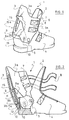
- la figure 1 est une vue en perspective d'une chaussure de ski partiellement découpée dans sa zone arrière pourvue de moyens de contrôle de la flexion selon l'invention ;
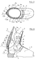
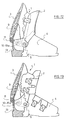
- les figures 2, 3 et 4 sont des vues de côté d'une chaussure selon la figure 1, vue en coupe partielle, montrant respectivement celle-ci en position ouverte, en position fermée, et en flexion avant;
- la figure 4a représente un détail de réalisation des moyens de contrôle de la flexion de la chaussure illustrée aux figures 1 à 4;
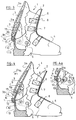
- la figure 5 est une vue de côté et en coupe partielle d'une chaussure selon une variante de réalisation des moyens de contrôle de la flexion ;
- la figure 6 est une vue de côté et en coupe partielle d'une chaussure selon une autre variante de réalisation des moyens de contrôle de la flexion ;
- la figure 7 est une vue de dessus en coupe selon la ligne VII VII de la chaussure de la figure 6 ;
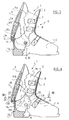
- les figures 8, 9 et 11 sont des vues de côté et en coupe partielle de chaussures selon d'autres variantes de réalisation des moyens de contrôle de la flexion ;
- les figures 12 et 13 sont des vues de côtés d'autres types de chaussures ; la figure 12 montrant une chaussure dont la partie antérieure de la tige est articulée sur le bas de coque, et la figure 13 illustrant une chaussure du type à ouverture par le dessus.
- Figure 1 is a perspective view of a ski boot partially cut in its rear area provided with flexure control means according to the invention;
- Figures 2, 3 and 4 are side views of a shoe according to Figure 1, partial sectional view, respectively showing the latter in the open position, in the closed position, and in forward bending;
- Figure 4a shows a detail of the means for controlling the flexion of the shoe illustrated in Figures 1 to 4;
- Figure 5 is a side view in partial section of a shoe according to an alternative embodiment of the flexure control means;
- Figure 6 is a side view in partial section of a shoe according to another alternative embodiment of the flexure control means;
- Figure 7 is a top view in section along line VII VII of the shoe of Figure 6;
- Figures 8, 9 and 11 are side views and partial section of shoes according to other alternative embodiments of the flexure control means;
- Figures 12 and 13 are side views of other types of shoes; FIG. 12 showing a shoe whose front part of the upper is articulated on the bottom of the shell, and FIG. 13 illustrating a shoe of the type with opening from above.
A titre d'exemple, mais non limitatif, la chaussure représentée sur les figures 1 à 11 est du type à entrée par l'arrière.By way of example, but not limiting, the shoe shown in FIGS. 1 to 11 is of the rear entry type.
Conformément à l'invention, la chaussure de ski présente une tige 1 constituée d'une partie antérieure 2, d'une partie postérieure 3, et d'un bas de coque 4 sur lequel la partie postérieure 3 de la tige 1 est reliée par l'intermédiaire d'un axe transversal 5 d'articulation.According to the invention, the ski boot has a
La chaussure représentée comporte également plusieurs systèmes de serrage 6 et de fermeture de la tige 1 sur le bas de jambe du skieur, comprenant chacun, d'une manière connue en soi, un lever tendeur 7 qui assujettit en tension un lien souple tel qu'une boucle à câble 8 entourant partiellement la partie antérieure 2 de la tige 1 pour relier chaque tendeur 7 fixé sur une aile 3a de la partie postérieure 3, ou capot arrière, à des points d'ancrage (non représentés) disposés sur l'autre aile 3a de la même partie 3, englobant au passage la partie antérieure 2, en vue de leur rapprochement.The shoe shown also comprises several systems for tightening 6 and closing the
Selon l'invention, la chaussure comporte des moyens de contrôle de la flexion en amplitude et en effort vers l'avant qui sont réalisés sur la partie postérieure 3 de la tige 1.According to the invention, the shoe comprises means for controlling the flexion in amplitude and in forward force which are produced on the
Comme cela est représenté sur les figures 1 à 4, ces moyens sont constitués par un étrier d'énergie 9 en forme de coquille dont deux ailes latérales 9a chevauchant au moins partiellement, dans sa partie arrière, le bas de coque 4, cet étrier 9 étant lui-même coiffé par les ailes latérales 3a de la partie postérieure 3 de la tige 1 contre laquelle il est plaqué de manière solidaire pour être entraîné en pivotement par rapport audit bas de coque 4, dans un mouvement postéroantérieur ou antéro-postérieur autour de deux axes 10 situés en retrait postérieurement à l'axe transversal d'articulation 5 de la partie postérieure 3 de ladite tige 1 sur le bas de coque 5. Ces axes 10 constituent des liaisons entre les ailes 9a de l'étrier 9 et celles 3a de la partie postérieure 3 de la tige 1 ainsi solidarisées entre elles.As shown in FIGS. 1 to 4, these means consist of a shell-
Dans un mouvement postéro-antérieur, lorsque la tige 1 est refermée sur le bas de jambe (fig. 3), l'étrier d'énergie 9 est entraîné en pivotement par la partie postérieure 3, de laquelle il est solidaire par les axes 10 précités, selon une course délimitée par une butée 11 ménagée sur le bas de coque 4 à sa partie supérieure au niveau du talon.In a postero-anterior movement, when the
La butée 11 coopère alors avec une butée complémentaire 12 de l'étrier 9 après un pivotement libre selon un angle prédéterminé de la tige 1 et plus précisément de sa partie postérieure 3 par rapport au bas de coque 4.The
A partir de cette position, où les butées 11 et 12 coopèrent entre elles, il correspond un début de contrôle de la flexion de la tige 1 s'exerçant dans le sens F1, par réaction de l'étrier 9 dans le sens inverse F2 contre la partie postérieure 3 de la tige 1 (fig. 4).From this position, where the stops 11 and 12 cooperate with each other, there corresponds a start of control of the bending of the
Cette réaction de l'étrier 9 est provoquée par le pivotement de la partie postérieure 3 de la tige 1 dans le sens postéro-antérieur, lequel pivotement génère celui de l'étrier 9 dans le sens antéro-postérieur du fait de la retenue de ce dernier contre la butée 11 et de sa liaison par les axes 10 avec ladite partie postérieure 3. Comme cela découle de l'évidence, pour autoriser le pivotement de l'étrier 9 dans le sens antéro-postérieur, l'ajustement de l'étrier 9 avec la partie postérieure 3 et le bas de coque 4, qui est pourvu de la butée 11, est prévu relativement libre, par exemple avec des jeux relatifs entre ladite butée 11 et la butée complémentaire 12 et/ou entre les axes de liaison 10 et au moins l'étrier 9 ou la partie postérieure 3 de la tige 1. Il est également possible, tel que cela est illustré schématiquement à la figure 4a, de prévoir une liaison 10a entre l'étrier 9 et la partie postérieure 3 de la tige 1 qui soit mobile en translation par rapport, au moins, à l'axe d'articulation 5 ou à la butée 11, lesquels sont fixes en position sur le bas de coque 4. Dans le cas présent, la liaison 10 est réalisée au moyen d'un axe de liaison 10 qui est positionné de manière fixe sur la partie postérieure 3 de la tige 1 et qui coopère avec une lumière oblongue 10b obtenue dans l'étrier d'énergie 9 et dans laquelle il peut coulisser.This reaction of the
Les butées 12 et 11 sont respectivement réalisées dans la partie inférieure 9b de l'étrier d'énergie 9 et dans la zone postérieure supérieure du bas de coque 4 correspondant au talon, et constituent des saillies approximativement à angle droit de formes complémentaires mais orientées dans des directions opposées de manière tête bêche, afin d'être en arc-boutement l'une sur l'autre par appui mutuel.The
Comme le montrent également les figures 1 à 4, l'étrier d'énergie est également susceptible de pivoter dans un mouvement antéro-postérieur selon une course de la butée 12 de l'étrier 9 limitée par une butée inférieure 13 du bas de coque 4 correspondant à une partie postérieure inférieure du talon, tel que par exemple le rebord supérieur de la semelle de la chaussure.As also shown in FIGS. 1 to 4, the energy stirrup is also capable of pivoting in an anteroposterior movement according to a stroke of the
Cette butée inférieure 13 est constituée par un épaulement horizontal obtenu de moulage avec le bas de coque 4.This
Les butées 11 et 13 respectivement supérieure et inférieure du bas de coque 4 ainsi définies sont espacées angulairement par rapport à l'axe 5 selon un certain angle, définissant sensiblement l'angle d'ouverture maximum de la partie postérieure 3 de la tige 1 en vue du chaussage (fig. 2).The
De manière à permettre l'entraînement de l'étrier d'énergie 9 au moins dans le sens antéro-postérieur de la partie postérieure 3 de la tige 1, un rebord 14 est réalisé en saillie vers l'extérieur à la partie inférieure 9b dudit étrier 9 constituant un épaulement d'appui de la partie postérieure 3 de la tige 1, au cours de l'ouverture de celle-ci.In order to allow the drive of the
L'étrier d'énergie 9 comporte également à sa partie postérieure, sensiblement dans sa zone médiane, une échancrure verticale 15 ouverte de manière évasée vers le haut dans cet exemple, apte à se déformer par rapprochement des lèvres de bordure 15a lors d'une flexion avant. L'échancrure 15 est dirigée à l'opposé des moyens de solidarisation 10 constitués par les axes de l'étrier 9 agissant dans la zone inférieure 3b de la partie postérieure 3 de la tige 1. L'étrier 9 est alors bloqué en pivotement vers l'avant sur la butée supérieure 11 du bas de coque 4, et à partir de ce moment, la partie postérieure 3 sollicite en flexion avant l'étrier 9 qui, par un effet résistant, se déforme élastiquement par rapprochement simultané des lèvres 15a de l'échancrure 15 et flambage de celles-ci.The
Dans l'exemple de réalisation décrit ci-dessus, le fait de disposer les axes 10 de l'étrier 9 en retrait par rapport à l'axe transversal 5 de la partie postérieure 3 sur le bas de coque 4, présente l'avantage de ne pas nécessiter un contact intime entre l'étrier 9 et l'intérieur de la partie postérieure 3 de la tige 1, et permet d'éviter un manque d'énergie en début de flexion, dû au jeu. En fait, de par la position des axes 10 de l'étrier d'énergie 9 par rapport à l'axe 5, on obtient dès la mise en contact des butées 11,12, respectivement du bas de coque 4 et de l'étrier 9, un basculement de ce dernier vers l'arrière provoquant avantageusement un rattrapage de jeu immédiat pouvant exister entre ledit étrier 9 et la partie postérieure 3 de la tige 1.In the embodiment described above, having the
Selon une variante de réalisation représentée sur la figure 5, celle-ci diffère essentiellement des précédentes en ce que l'étrier d'énergie 9A pivote, par rapport au bas de coque 4, autour d'un axe de liaison se confondant avec l'axe transversal 5 d'articulation de la partie postérieure 3 de la tige 1 correspondant sensiblement aux malléoles, ceci dans un but de simplification de réalisation.According to an alternative embodiment shown in FIG. 5, this differs essentially from the previous ones in that the
Selon une autre variante de réalisation représentée sur les figures 6 et 7, la butée de l'étrier d'énergie 9B est constituée par des parties de bordure d'extrémité 15c de chacune de ses ailes 16,17 aptes à coopérer avec la zone de butée supérieure du bas de coque 4, constituée en l'occurrence par deux épaulements complémentaires 18 obtenus sur des ailes latérales 4a du bas de coque 4 en correspondance des parties de bordure 15 des ailes 16, 17 de l'étrier d'énergie 9B.According to another alternative embodiment shown in FIGS. 6 and 7, the abutment of the energy stirrup 9B is formed by
Egalement selon ce mode de réalisation représenté sur les figures 6 et 7, l'étrier d'énergie 9B est solidarisé de la partie postérieure 3 de la tige 1, que ce soit dans un sens antéro-postérieur ou postéro-antérieur, par l'intermédiaire d'un tenon 19 engagé dans une entaille 20 correspondante réalisée dans la zone inférieure de la partie postérieure 3 de la tige 1.Also according to this embodiment shown in FIGS. 6 and 7, the energy stirrup 9B is secured to the
De cette manière, l'on assure un meilleur suivi de l'étrier 9B par rapport à la partie postérieure 3 de la tige 1.In this way, better monitoring of the stirrup 9B is ensured relative to the
Selon une autre variante de réalisation représentée sur la figure 8, l'étrier d'énergie 9C est solidarisé de la partie postérieure 3 de la tige 1 dans les sens antéro-postérieur ou postéro-antérieur par l'intermédiaire d'un moyen d'assemblage effectif par exemple un rivet 21 reliant les zones inférieures 9b, 3b respectivement de l'étrier 9C et de la partie postérieure 3 de la tige 1.According to another alternative embodiment shown in FIG. 8, the
Comme cela a été décrit en référence aux figures 1 à 8 qui précèdent, l'étrier d'énergie 9 est obtenu avec une échancrure verticale 15 ouverte vers le haut pour améliorer sa flexibilité et localiser ses zones déformables. Il va de soi que l'étrier peut aussi être prévu déformable dans son ensemble ; dans ce cas, les zones déformables se situent simplement d'une manière plus ou moins aléatoire sur les ailes 9a et sur la partie médiane de l'étrier d'énergie 9.As described with reference to Figures 1 to 8 above, the
Encore, l'étrier d'énergie 9 peut également être prévu pour travailler davantage en flexion dans sa partie inférieure, à l'inverse des modes de réalisation précédents ; à cet effet, par exemple, tel que cela est représenté à la figure 9, l'étrier d'énergie 9D est solidarisé de la partie postérieure 3 de la tige 1 dans sa zone supérieure 9c et son échancrure verticale 15 est ouverte vers le bas dans sa zone inférieure 9b. Dans la présente construction, la butée de l'étrier d'énergie 9D est constituée pardes parties de bordure d'extrémité 15d de chacune de ses ailes 16d, 17d qui viennent coopérer avec la zone de butée supérieure du bas de coque 4 telle que deux épaulements 18 obtenus sur les ailes latérales 4a de ce dernier. Il est bien entendu que l'étrier d'énergie 9D peut être lié à la partie postérieure 3 de la tige 1 à l'aide de différents moyens d'assemblage qui peuvent être par exemple un rivet 21 ou un ensemble tenon 19-entaille 20 tel qu'illustré aux figures 6 et 7.Again, the
Dans la variante de réalisation de l'invention illustrée aux figures 10 et 11, l'étrier 9 et la partie postérieure 3 de la tige 1 sont reliés entre eux par l'intermédiaire d'une liaison mobile 10a dans laquelle l'axe 10 est réglable sur ladite partie postérieure 3 dans sa position relative entre l'axe d'articulation 5 et la butée 11. A cet effet, dans cet exemple de construction, l'axe 10 est pourvu d'un épaulement cranté 25 destiné à coopérer avec une lumière oblongue 26 à bords crantés obtenue dans la partie postérieure 3 de tige. Cet aménagement de la liaison 10a permet ainsi de varier le rapport des bras de levier déterminés par la position de l'axe 10 avec la butée 11 et l'axe d'articulation 5 et, intrinsèquement, l'amplitude du pivotement imposé à l'étrier 9 par la tige 1, lorsque la partie postérieure 3 de celle-ci fléchit dans le sens F1. Il résulte d'une telle réalisation que le contrôle de la flexion peut, à partir d'un étrier 9 et d'une partie postérieure 3 de tige donnés, être modifiable en amplitude et en effort.In the variant embodiment of the invention illustrated in FIGS. 10 and 11, the
Il est entendu que des variantes de construction peuvent être mises en oeuvre sans pour cela sortir du cadre de l'invention. On peut notamment associer à l'étrier d'énergie 9 un moyen ou dispositif de réglage spécifique de sa flexibilité indépendamment de l'aménagement d'une liaison 10a réglable en position telle que celle qui vient d'être décrite aux figures 10 et 11 qui précèdent. Le moyen ou dispositif de réglage (non représenté) est, par exemple, un curseur monté coulissant dans l'échancrure verticale 15 de l'étrier d'énergie 9.It is understood that construction variants can be implemented without departing from the scope of the invention. One can in particular associate with the
Enfin, dans la description de l'invention en référence aux figures 1 à 11, la chaussure montrée à titre d'exemple, est du type à entrée par l'arrière : il est évident que l'invention n'est pas limitée à une telle chaussure et peut concerner une chaussure du type à "entrée mixte", figure 12, ou du type à "entrée par le dessus", figure 13. Dans ces chaussures, l'étrier 9 est monté sur la partie postérieure 3 de la tige 1 de la même manière que dans les exemples précédents et permet ainsi de contrôler en amplitude et en effort la flexion de ladite partie postérieure 3 de la tige vers l'avant. Il est évident que l'étrier d'énergie 9 peut, selon le comportement souhaité de la chaussure, assurer à lui seul le contrôle de la flexion de la tige 1 de la chaussure. Egalement, l'étrier 9 peut être associé à un autre dispositif ou moyen de contrôle de la flexion, d'un type connu, qui agit au niveau de la partie antérieure 2 de la tige 1 par rapport au bas de coque 4 ; les efforts résistants à la flexion de la tige 1 vers l'avant sont alors répartis entre la partie postérieure 3 de cette dernière qui tend à tirer le bas de jambe du skieur vers l'arrière, et entre la partie antérieure 2 qui tend à repousser ledit bas de jambe.Finally, in the description of the invention with reference to Figures 1 to 11, the shoe shown by way of example, is of the rear entry type: it is obvious that the invention is not limited to a such a shoe and may relate to a shoe of the "mixed entry" type, FIG. 12, or of the "top entry" type, FIG. 13. In these shoes, the
Avantageusement, et quel que soit le mode de réalisation choisi, l'étrier d'énergie 9, 9A, 9B, 9C peut être obtenu par moulage de matière plastique de manière monobloc.Advantageously, and whatever the embodiment chosen, the
Il est entendu que des variantes de construction peuvent être mises en oeuvre sans pour cela sortir du cadre de l'invention.It is understood that construction variants can be implemented without departing from the scope of the invention.
Claims (12)
caractérisée en ce que les moyens de contrôle de la flexion en amplitude et en effort sont constitués par un étrier d'énergie (9, 9A, 9B, 9C, 9D) solidaire de la partie postérieure (3) de la tige (1), interposé entre cette dernière (3) et le bas de coque (4) et susceptible d'être entraîné en pivotement par ladite partie postérieure (3) par rapport audit bas de coque (4), dans un mouvement dirigé dans le sens postéro-antérieur, selon une course délimitée par une zone de butée fixe (11, 18) ménagée sur le bas de coque (4) à sa partie supérieure apte à coopérer avec une zone de butée complémentaire mobile (12, 15c, 15d) de l'étrier (9, 9A, 9b, 9C, 9D) lorsque la tige (1) est fermée sur le bas de jambe du skieur en position de pratique du ski.Alpine ski boot comprising a rigid shell of which a shell bottom (4) is surmounted by a rod (1) at least partially articulated on the latter around a transverse axis (5), and comprising at least one front part ( 2) and a rear part (3) to allow the passage of the foot in the open position, a rod closing assembly (1) forming a collar on the lower leg, consisting of a tightening system (6) surrounding at least partially the rod (1) to be tensioned by a tensioning lever (7) fixed on one of the front (2) and rear (3) parts constituting said rod (1), means for controlling the bending in amplitude and in forward force being carried out on the rear part (3) of the rod (1),
characterized in that the means for controlling the flexion in amplitude and in force consist of an energy stirrup (9, 9A, 9B, 9C, 9D) integral with the rear part (3) of the rod (1), interposed between the latter (3) and the bottom of the shell (4) and capable of being pivoted by said rear part (3) relative to said bottom of shell (4), in a movement directed in the postero-anterior direction , along a stroke delimited by a fixed stop zone (11, 18) formed on the bottom of the shell (4) at its upper part capable of cooperating with a mobile complementary stop zone (12, 15c, 15d) of the stirrup (9, 9A, 9b, 9C, 9D) when the rod (1) is closed on the lower leg of the skier in the ski practice position.
Applications Claiming Priority (2)
| Application Number | Priority Date | Filing Date | Title |
|---|---|---|---|
| FR9103668A FR2674106A1 (en) | 1991-03-21 | 1991-03-21 | ALPINE SKI BOOT WITH ENERGY CALIPER ARTICULATED ON THE REAR HOOD. |
| FR9103668 | 1991-03-21 |
Publications (1)
| Publication Number | Publication Date |
|---|---|
| EP0504768A1 true EP0504768A1 (en) | 1992-09-23 |
Family
ID=9411150
Family Applications (1)
| Application Number | Title | Priority Date | Filing Date |
|---|---|---|---|
| EP92104465A Withdrawn EP0504768A1 (en) | 1991-03-21 | 1992-03-16 | Alpine ski boot having an articulated movement clamp on the rear shell |
Country Status (4)
| Country | Link |
|---|---|
| US (1) | US5353528A (en) |
| EP (1) | EP0504768A1 (en) |
| JP (1) | JPH0576401A (en) |
| FR (1) | FR2674106A1 (en) |
Cited By (2)
| Publication number | Priority date | Publication date | Assignee | Title |
|---|---|---|---|---|
| AT402363B (en) * | 1993-08-19 | 1997-04-25 | Koeflach Sportgeraete Gmbh | Ski, mountain, ice-skating or roller-skating shoe with a plastic shell and method for producing the said shoe |
| FR2758092A1 (en) * | 1997-01-08 | 1998-07-10 | Burton Corp | FIXING ASSEMBLY FOR MONOSKI |
Families Citing this family (9)
| Publication number | Priority date | Publication date | Assignee | Title |
|---|---|---|---|---|
| FR2733125B1 (en) * | 1995-04-19 | 1997-07-04 | Salomon Sa | SHOE WITH ROD BENDING CONTROL |
| FR2740011B1 (en) * | 1995-10-20 | 1997-12-12 | Salomon Sa | ADJUSTABLE SHOE SHOE |
| FR2752147B1 (en) * | 1996-08-06 | 1998-10-09 | Salomon Sa | SPORTS SHOE |
| FR2767034B1 (en) * | 1997-08-05 | 1999-09-10 | Salomon Sa | SPORT SHOE WITH DETERMINED FLEXIBILITY |
| US7401419B2 (en) | 2002-07-31 | 2008-07-22 | Adidas International Marketing B.V, | Structural element for a shoe sole |
| DE102005006267B3 (en) | 2005-02-11 | 2006-03-16 | Adidas International Marketing B.V. | Shoe sole e.g. for sport shoe, has heel which has bowl or edge having form corresponding to heel of foot and underneath bowl and or edge of heel side panels which are connected to separate rear side panel |
| DE10234913B4 (en) | 2002-07-31 | 2005-11-10 | Adidas International Marketing B.V. | sole |
| DE102006015649B4 (en) | 2006-04-04 | 2008-02-28 | Adidas International Marketing B.V. | shoe |
| EP2572599B1 (en) * | 2011-09-26 | 2015-04-22 | Rossignol Lange S.R.L. | Shell of a ski boot with spoiler |
Citations (4)
| Publication number | Priority date | Publication date | Assignee | Title |
|---|---|---|---|---|
| DE3530243A1 (en) * | 1985-08-23 | 1987-03-05 | Josef Lederer | Ski boot |
| FR2619684A1 (en) * | 1987-09-02 | 1989-03-03 | Salomon Sa | ALPINE SKI BOOT WITH ARTICULATED UPPER |
| EP0350023A2 (en) * | 1988-07-07 | 1990-01-10 | TECNICA SpA | Adjustment device of the flexibility for ski boots |
| EP0380444A1 (en) * | 1989-01-27 | 1990-08-01 | Lange International S.A. | Ski boot |
Family Cites Families (17)
| Publication number | Priority date | Publication date | Assignee | Title |
|---|---|---|---|---|
| GB836755A (en) * | 1957-12-09 | 1960-06-09 | Goodrich Co B F | Improvements in and relating to polymers |
| US3521385A (en) * | 1968-05-02 | 1970-07-21 | Melvin W Dalebout | Ski boot |
| CH512204A (en) * | 1969-12-23 | 1971-09-15 | Rieker & Co Dr Justus | Ski boots |
| US3619914A (en) * | 1970-02-13 | 1971-11-16 | Lange & Co | Boot tensioning device |
| US3713231A (en) * | 1970-06-11 | 1973-01-30 | Hope Kk | Ski boot |
| CH587668A5 (en) * | 1974-11-28 | 1977-05-13 | Salomon & Fils F | |
| FR2305948A1 (en) * | 1975-04-03 | 1976-10-29 | Trappeur | Ski boot made by injection moulding - has L-shaped metallic stiffener with curved section introduced during moulding |
| FR2330345A1 (en) * | 1975-11-04 | 1977-06-03 | Trappeur | ADVANCED SKI BOOTS |
| US4078322A (en) * | 1976-08-04 | 1978-03-14 | Engineered Sports Products, Inc. | Ski boot |
| US4095356A (en) * | 1976-10-15 | 1978-06-20 | Scott Usa, Inc. | Boot with pivoted upper |
| FR2454767A2 (en) * | 1978-06-16 | 1980-11-21 | Salomon & Fils F | SKI BOOT |
| US4669202A (en) * | 1984-09-28 | 1987-06-02 | Ottieri Enterprises | Ski boot |
| US4565017A (en) * | 1984-09-28 | 1986-01-21 | Ottieri Enterprises | Ski boot |
| US4691454A (en) * | 1984-09-28 | 1987-09-08 | Ottieri Enterprises | Ski boot closure system |
| IT1214138B (en) * | 1987-09-15 | 1990-01-10 | Nordica Spa | HEEL LOCKING DEVICE, ESPECIALLY FOR SKI BOOTS. |
| ATE106200T1 (en) * | 1988-12-13 | 1994-06-15 | Salomon Sa | REAR ENTRY ALPINE SKI BOOT |
| FR2652240B1 (en) * | 1989-09-28 | 1992-01-24 | Salomon Sa | DEVICE FOR ADJUSTING THE POSITION OF A LEVER RELATIVE TO THE UPPER OF A SHOE. |
-
1991
- 1991-03-21 FR FR9103668A patent/FR2674106A1/en active Granted
-
1992
- 1992-03-16 EP EP92104465A patent/EP0504768A1/en not_active Withdrawn
- 1992-03-17 JP JP4060433A patent/JPH0576401A/en not_active Withdrawn
-
1993
- 1993-11-12 US US08/150,797 patent/US5353528A/en not_active Expired - Fee Related
Patent Citations (4)
| Publication number | Priority date | Publication date | Assignee | Title |
|---|---|---|---|---|
| DE3530243A1 (en) * | 1985-08-23 | 1987-03-05 | Josef Lederer | Ski boot |
| FR2619684A1 (en) * | 1987-09-02 | 1989-03-03 | Salomon Sa | ALPINE SKI BOOT WITH ARTICULATED UPPER |
| EP0350023A2 (en) * | 1988-07-07 | 1990-01-10 | TECNICA SpA | Adjustment device of the flexibility for ski boots |
| EP0380444A1 (en) * | 1989-01-27 | 1990-08-01 | Lange International S.A. | Ski boot |
Cited By (4)
| Publication number | Priority date | Publication date | Assignee | Title |
|---|---|---|---|---|
| AT402363B (en) * | 1993-08-19 | 1997-04-25 | Koeflach Sportgeraete Gmbh | Ski, mountain, ice-skating or roller-skating shoe with a plastic shell and method for producing the said shoe |
| FR2758092A1 (en) * | 1997-01-08 | 1998-07-10 | Burton Corp | FIXING ASSEMBLY FOR MONOSKI |
| US6027136A (en) * | 1997-01-08 | 2000-02-22 | The Burton Corporation | System for preventing toe-edge travel of a hi-back |
| US6283495B1 (en) | 1997-01-08 | 2001-09-04 | The Burton Corporation | System for preventing toe-edge travel of a hi-back |
Also Published As
| Publication number | Publication date |
|---|---|
| JPH0576401A (en) | 1993-03-30 |
| US5353528A (en) | 1994-10-11 |
| FR2674106B1 (en) | 1995-02-10 |
| FR2674106A1 (en) | 1992-09-25 |
Similar Documents
| Publication | Publication Date | Title |
|---|---|---|
| EP0644730B1 (en) | Boot for skiing and the like | |
| EP0278281B1 (en) | Ski boot | |
| EP0486940B1 (en) | Alpine ski boot | |
| FR2640516A1 (en) | SAFETY FASTENING FOR SKI INTENDED TO MAINTAIN, IN A RELIABLE MANNER, THE FRONT OF A SKI-FITTED SHOE | |
| FR2583272A1 (en) | ALPINE SKI SHOE | |
| EP0895727B1 (en) | Sportsshoe with determined flexibility | |
| EP0504768A1 (en) | Alpine ski boot having an articulated movement clamp on the rear shell | |
| CH663329A5 (en) | SKI BOOT. | |
| EP0521282A1 (en) | Skiboot with pivot locking device of the upper quarter | |
| FR2617380A1 (en) | Boot including a device for adjusting the tilt of the axis of articulation of the upper on the shell | |
| FR2722421A1 (en) | ALPINE SKI FIXING ELEMENT | |
| EP0634197B1 (en) | Alpine ski binding | |
| EP0504769B1 (en) | Alpine ski boot having an articulated movement damper on the bottom shell | |
| EP0699399A1 (en) | Skiboot | |
| FR2672189A1 (en) | SKI SHOE WITH REAR HOOD JOINED ON HULL ARM. | |
| EP1358916A1 (en) | A sport shoe for practising a gliding sport or snowboard binding with snap fastener flaps | |
| CH667977A5 (en) | SKI SHOE WITH REAR ENTRY. | |
| EP0664968B1 (en) | Skiboot with hinged forepart of the cuff | |
| EP0648439B1 (en) | Ski boot | |
| FR2632871A1 (en) | SKI SHOE WITH AUTOMATIC CLOSURE | |
| EP0193686A1 (en) | Restraining device for a shoe at a ski | |
| EP0712586A1 (en) | Skiboot | |
| FR2583271A1 (en) | Alpine ski boot | |
| FR2609378A1 (en) | FOOTWEAR AND FIXATION OF BACKGROUND SKI | |
| EP2959949B1 (en) | Device for accommodating a shoe on a snow gliding device |
Legal Events
| Date | Code | Title | Description |
|---|---|---|---|
| PUAI | Public reference made under article 153(3) epc to a published international application that has entered the european phase |
Free format text: ORIGINAL CODE: 0009012 |
|
| AK | Designated contracting states |
Kind code of ref document: A1 Designated state(s): CH DE FR IT LI |
|
| 17P | Request for examination filed |
Effective date: 19930311 |
|
| 17Q | First examination report despatched |
Effective date: 19930803 |
|
| STAA | Information on the status of an ep patent application or granted ep patent |
Free format text: STATUS: THE APPLICATION IS DEEMED TO BE WITHDRAWN |
|
| 18D | Application deemed to be withdrawn |
Effective date: 19950912 |