EP2959949B1 - Device for accommodating a shoe on a snow gliding device - Google Patents
Device for accommodating a shoe on a snow gliding device Download PDFInfo
- Publication number
- EP2959949B1 EP2959949B1 EP15001672.3A EP15001672A EP2959949B1 EP 2959949 B1 EP2959949 B1 EP 2959949B1 EP 15001672 A EP15001672 A EP 15001672A EP 2959949 B1 EP2959949 B1 EP 2959949B1
- Authority
- EP
- European Patent Office
- Prior art keywords
- bow
- footing
- seat
- connecting element
- arch
- Prior art date
- Legal status (The legal status is an assumption and is not a legal conclusion. Google has not performed a legal analysis and makes no representation as to the accuracy of the status listed.)
- Not-in-force
Links
Images


Classifications
-
- A—HUMAN NECESSITIES
- A63—SPORTS; GAMES; AMUSEMENTS
- A63C—SKATES; SKIS; ROLLER SKATES; DESIGN OR LAYOUT OF COURTS, RINKS OR THE LIKE
- A63C10/00—Snowboard bindings
- A63C10/02—Snowboard bindings characterised by details of the shoe holders
- A63C10/08—Toe or heel stirrups; Clamps
-
- A—HUMAN NECESSITIES
- A63—SPORTS; GAMES; AMUSEMENTS
- A63C—SKATES; SKIS; ROLLER SKATES; DESIGN OR LAYOUT OF COURTS, RINKS OR THE LIKE
- A63C10/00—Snowboard bindings
- A63C10/16—Systems for adjusting the direction or position of the bindings
- A63C10/20—Systems for adjusting the direction or position of the bindings in longitudinal or lateral direction relative to the board
-
- A—HUMAN NECESSITIES
- A63—SPORTS; GAMES; AMUSEMENTS
- A63C—SKATES; SKIS; ROLLER SKATES; DESIGN OR LAYOUT OF COURTS, RINKS OR THE LIKE
- A63C10/00—Snowboard bindings
- A63C10/16—Systems for adjusting the direction or position of the bindings
- A63C10/22—Systems for adjusting the direction or position of the bindings to fit the size of the shoe
-
- A—HUMAN NECESSITIES
- A63—SPORTS; GAMES; AMUSEMENTS
- A63C—SKATES; SKIS; ROLLER SKATES; DESIGN OR LAYOUT OF COURTS, RINKS OR THE LIKE
- A63C10/00—Snowboard bindings
- A63C10/24—Calf or heel supports, e.g. adjustable high back or heel loops
-
- A—HUMAN NECESSITIES
- A63—SPORTS; GAMES; AMUSEMENTS
- A63C—SKATES; SKIS; ROLLER SKATES; DESIGN OR LAYOUT OF COURTS, RINKS OR THE LIKE
- A63C10/00—Snowboard bindings
- A63C10/02—Snowboard bindings characterised by details of the shoe holders
- A63C10/04—Shoe holders for passing over the shoe
Definitions
- the invention relates to the field of equipment for the practice of sliding sports, especially on snow. It is particularly directed to the interface between the user's foot and a gliding board. It proposes for this purpose a reception device of a foot or a shoe on a gliding machine.
- Such sets are, for example, intended for snowboarding or snowboarding.
- reception devices able to receive, each, a shoe of the user.
- These reception devices comprise a seat portion intended to be fixed relative to the gliding board. This portion of the seat is adapted to receive the sole of the shoe. It is in particular by the seat that is applied to the gliding machine, at least in majority, the weight exerted by the user.
- the known reception devices also include means for maintaining the shoe. On the one hand, they comprise parts providing lateral support of the shoe and, on the other hand, at least one attachment of said shoe to the seat, for example, by links.
- the assembly thus offers a home for the boot that is able to hold it sufficiently in position relative to the gliding machine and to authorize a transmission of forces applied by the user for the control of the machine, for example when 'a catch of edges.
- the arch may have a concave shape, partially surrounding the heel of the foot or the shoe.
- the arch extends from a lateral edge of the seat, towards the other lateral edge, by traversing the rear part of the reception device so as to offer a cohesion element with the foot, generally at least by the back of the foot joint.
- the hoop is not intended to deform.
- This rigidity provides a good support of the shoe but can be inconvenient for the user to use, especially during lateral or forward movements.
- the hoop creates areas of hard contact with the shoe and more particularly when tilting the shoe around a longitudinal axis to the attachment, which can be a source of discomfort.
- this design limits foot movement relative to the board.
- the surfer wants more freedom of movement to get more ease and control of his jumps.
- this design induces high stresses on the structure of the binding.
- the fasteners circling the shoe by the top of the instep are exposed at high stresses.
- the hoop is also strongly stressed, particularly in flexion, during the forward movements of the surfer.
- One goal is to provide a home device offering more freedom of movement for the foot or the shoe compared to the seat.
- Another goal is to offer a comfortable home device.
- Another object of the invention is to provide a robust home device.
- the invention proposes a device for receiving a foot or a shoe on a gliding apparatus comprising: a seat which extends in a longitudinal direction from a rear end to a front end, and in width, from a first edge to a second edge, and a hoop extending towards the rear end of the seat, the hoop being connected to the seat by a connecting system comprising first and second points of grip, these attachment points providing rigidity ensuring maintenance and mechanical consistency between the seat and the arch so that the hoop is self-supporting.
- the docking device is characterized in that the connecting system comprises at least one connecting element connecting a rear lateral portion of the bow to the seat so as to limit a relative movement of spacing between the rear lateral portion. of the arch and the seat, while allowing the relative movement of approach between the rear side of the arch and the seat.
- a movement is authorized between the seat and the rear part of the arch so that these parts can accommodate variations of solicitations of the foot or the shoe. At the same time, this capacity is limited so as not to penalize the maintenance and preserve the structure of the reception device.
- connection between the hoop and the seat is less rigid, at least in a limited operating phase clearance, so that it is less constrained and it is thus preserved the risk of rupture.
- the connecting elements provide flexibility in the behavior by allowing an energy twist or not the foot around an axis longitudinal of the device. The realization of figures of style is then facilitated.
- Another aspect of the present invention relates to a gliding apparatus comprising at least one docking device as described above.
- the longitudinal direction of the reception device means the direction corresponding to the length of the foot or the shoe of the user and directed in the direction marked "x".
- this direction "x" is generally directed obliquely relative to the longitudinal direction of the gliding machine, including a surfboard.
- width means a direction directed perpendicular to the longitudinal direction and corresponding to a width dimension of the foot or the shoe of the user. This direction is illustrated at the "y” mark.
- the terms “height” or “vertical direction” denote a dimension directed according to the height of the user in the rest position and corresponds to the direction marked "z”.
- a first piece is, according to the present description, considered "integral" with another piece when these two pieces are linked for at least one degree of freedom, it being understood that the pieces may not be linked for other degrees of freedom.
- freedom For example, a part may have freedom of movement in rotation along an axis relative to another part and be linked in translation in another direction.
- a part is fixed in one direction when its mobility is prohibited relative to another part in said direction. This does not necessarily imply that the part is also fixed in other directions, in translation or in rotation.
- the term "fixed" in one direction does not necessarily imply a complete embedding of two pieces.
- the front part of the device is a part directed more towards the distal end of the shoe or the foot of the user, that is to say towards the toes.
- the term “rear” refers to parts directed towards the rear end of the foot or shoe at the heel.
- the adjective “median” or “median” refers to an area in the middle of the dimension in the longitudinal direction of a room.
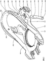
- the figure 1 generally presents an embodiment of the reception device 1 of the invention to report on a gliding board 10.
- the receiving device 1 comprises a seat 100, an upper face 101 is adapted to cooperate with the foot or the user's shoe via the sole. Opposite the upper face 101, a lower face 102 is intended to come into contact with an upper face 11 of the gliding board 10.
- the seat 100 generally comprises a front end 103 and an end. back 104 for example spotted at figures 3 and 5 . These ends 103, 104 are joined, substantially in the longitudinal direction "x".
- the seat is delimited laterally by a first - 105 - and a second edge 106.
- Known relative fastening means between the gliding board 10 and the seat 100 are provided.
- the reception device 1 comprises different elements of retention of the foot / shoe inside the device.
- a hoop 200 is formed so as to extend laterally relative to the seat 100 and to the rear part of the seat and therefore, the device.
- the arch is designed to surround the heel and lateral (lateral and medial) edges of the shoe.
- the hoop 200 is joined to the seat 100 via a first and a second attachment point 108.
- the first point of attachment 107 corresponds to the triangulated connection between a lateral portion 201 of the arch 200 and a lateral portion 105 of the seat 100.
- the attachment points 107, 108 are formed at the front part of the seat 100, that is to say, in front of its median zone, towards the front end. 103.
- the first 107 and second attachment points 108 participate in a connection system between the seat 100 and the arch 200 providing rigidity ensuring the maintenance and mechanical consistency between these two parts.
- the seat 100 and the hoop 200 form a single monolithic piece, connected at the points of attachment 107, 108.
- the hoop can be a separate part of the seat.
- the arch is attached by being fixed on the seat by appropriate fastening means.
- the arch forms a closed loop shaped to follow the morphology of the shoe.
- Each arch comprises two lateral arms extending towards the rear of the device and connected by a curved part in its rear part.
- the invention proposes a capacity for relative movements of the rear part of the arch 200 and the seat 100.
- the connection system is therefore configured to allow this relative deflection.
- the arch 200 extends rearwardly and is included in a plane inclined relative to the plane of the seat, at an angle of between 15 and 45 °.
- This inclination makes it possible to increase the length of the lateral portions 201 of the arch which facilitates their bending around an axis substantially connecting the points of attachment 107, 108.
- this bending deformation can be likened to a rotation around an axis directed according to the dimension "y" of the device and centered on the center of the first 107 and second attachment points 108.
- the movement results in a relative movement of spacing or approximation between the rear part of the arch and the seat. This relative movement is substantially vertical.
- connection system may comprise additional links or the points of attachment 107, 108 may be made in several parts.
- the reception device 1 comprises, in the illustrated examples, links before 410 reported at the seat 100 through attachment zones 109 and allowing the establishment of a holding element of the front of the foot of the shoe, at the toes.
- rear links 420 are reported at the level of the seat allowing the establishment of an element of holding the instep of the shoe.
- the links 410 and 420 are complementary to hold the user's shoe in position at two distinct zones along the longitudinal dimension of the reception device 1.
- another element holding the shoe in position is constituted by a rear support element 300 extending along the height dimension of the receiving device 1 so as to extend the hoop 200 in this direction and serve as additional support element of the back of the boot on the docking device 1.
- the rear support element 300 has a substantially casing shape adapted to match the shape of the rear of the boot. the shoe. It is articulated relative to the arch 200 via a first - 301 - and a second articulation zones 302 diagrammatically shown in FIG. Figures 1 and 2 .
- the element 300 bears on the arch 200.
- the rear support element 300 is equipped with a stop 303 adapted to be applied on a portion of the arch 200 in a maximum position of pivot backwards.
- the rear support element 300 is pivotally mounted relative to the seat 100 and not with respect to the hoop 200.
- connection system placed between the seat 100 and the arch 200 allows a residual freedom of movement and in particular a relative movement allowing a bringing closer of the rear part of the arch 200 to the seat 100 is a spacing, of opposite direction in the same direction of movement, which due to the low angles used, corresponds to a displacement on an angular sector substantially comparable to a vertical translation between the rear part of the arch 200 and the rear part of the seat 100.
- the relative movement of spacing or approximation is, according to the invention, limited in its race so, in particular, not to allow excessive spacing of the rear part of the arch 200 relative to the seat 100.
- the latter benefits from a phase in which the arch 200 substantially follows these lateral movements or forward, and a phase during which the rear part of the arch 200 n is more able to be removed from the seat 100 so as to avoid too large spacing may penalize the holding of the shoe and to avoid too much stress on the points of attachment 107, 108 between the seat 100 and the arch 200.
- connecting elements 500 two embodiments of which are illustrated in the figures.
- connection system thus comprises, at the level of at least one edge 105, 106, a connecting element 500 connecting a rear lateral portion 207, 208 of the arch to the seat so as to limit a relative movement of spacing between the rear lateral portion of the arch and the seat, while allowing the relative movement of approximation between the rear lateral part of the arch and the seat.
- the connecting element 500 disposed on each side of the seat 100 is an isolated element.
- the connecting element 500 is coupled to a compressible element 600.
- each connecting element 500 is shown each situated on an edge 105, 106 different from the seat 100. More particularly, the connecting elements 500 may be situated in the rear part of the first and second edges 106 of the In this way, each connecting element 500 also cooperates with a rear lateral portion 207, 208 of the arch 200.
- the connecting element 500 is configured to allow, according to a limited range of movement, the displacement of the rear part of the arch 200 relative to the seat 100 by changing the configuration of the elements 500.
- configuration change means a deformation of the connecting element 500, a movement of the element 500 or any other change in shape or position of the element 500 to achieve a limitation of the deflection.
- the configuration change of the connecting element 500 allowing the movement is however limited so that only a relative mobility race between the arch 200 and the seat 100 is possible.
- the element 500 is in the form of a tab, for example an elongate piece of a polymeric material and in particular polyurethane or polycarbonate, said tab being mounted firstly on the arch 200 and secondly on the seat 100.
- the connecting elements are cooperating by areas where connections are made.
- a tab making a connecting element 500 is secured to a rear lateral portion 207, 208 of the arch 200 so as to link their displacement in the direction of the desired relative movement between the seat 100 and the seat. arch 200, namely the spacing or the approximation.
- this fixing in position is carried out by means of a shaft 205 passing through a hole 504 located at a first end 501 of the connecting element 500 in the form of a tab and cooperating with a bearing made in FIG. 200.
- the displacement of the rear portion of the arch 200 causes the same displacement of the leg 500 when the tab is not requested.
- the tab can also rotate around the shaft 205.
- the connecting element is rotatably mounted on the hoop. This allows less constrain the connecting element during the deformation of the arch.
- FIG. 7 This configuration is more particularly visible with reference to the second embodiment and in particular to the figure 7 , the mounting of the connecting element 500 being similar between the two illustrated embodiments.
- the arch 200 has in this case, at each of these side portions 201, 202 a slot 204 substantially oriented in the direction in height corresponding to the direction "z".
- This slot 204 passes right through, the arch 200 at the hole 206 forming the bearing of the shaft 205 so that the first end 501 of the connecting element 500 can be inserted inside the 200 to be held by the shaft 205.
- the latter can, for example, be in the form of a screw whose head performs a blocking of one side of the arch 200 and cooperating with a member of opposite mounting, performing the function of a nut.
- the vertical slot 204 of each lateral portion 201, 202 of the arch 200 has edges along its height so as to provide lateral guidance of the connecting element 500.
- the connecting element 500 has a mobility relative to the seat 100. More particularly, in the examples, the tab forming the connecting element 500 and having a substantially elongated shape in the direction "z", has a second end 502 adapted to be inserted into a housing 110 formed within an edge 105 or 106 of the seat 100 in which the second end 502 has a mobility capacity, in the direction of the relative movement between the arch 200 and the seat 100.
- housing 110 is visible in the exploded view of the figure 7 at which the housing 110 is directed along the height of the host device 1 and has an upper opening placed opposite the slot 204. This upper opening is intended to be traversed by the connecting element 500 In this example, the housing 110 passes right through the seat 100 and forms a slot.
- the housing 110 is dimensioned to guide the connecting element 500, and more particularly its second end 502, during the displacement of the connecting element resulting from the deformation of the arch.
- the second end 502 can then slide in a guide direction, substantially vertical in this example.
- the connecting element is able to move by sliding relative to the seat, during the relative movement of spacing or bringing together the rear lateral portion of the arch and the seat.
- the connecting element 500 is assembled to the entire host device 1 through a lower opening of the housing 110 opening on the lower face 102 of the seat. This lower opening is located opposite the upper opening opposite the arch 200.
- the element 500 can be threaded into the housing 110, on the side of the underside of the seat , so as to pass through said housing 110.
- the element 500 is then placed so that its first end 501 is introduced into the slot 204 of the arch 200.
- the first end 501 is then fixed to the arch by the shaft 205. In these cases, it is therefore between the seat 100 and the connecting element 500 that the relative freedom of movement between the seat 100 and the rear part of the arch 200 is produced.
- the connecting element 500 has a stop element 503, an exemplary embodiment of which is illustrated in perspective at the figure 7 and in section in the two embodiments illustrated at the level of figures 4 and 6 .
- the stop element 503 may be in the form of a projecting protuberance on one and / or the other of the faces of the second end 502 of the tab forming the element of FIG. link 500.
- a protuberance of circular section forming a stud on the surface of the tab may be suitable.
- the stop element 503 cooperates with an abutment surface 111 which is equipped with the seat 100 and in particular, in the illustrated embodiments, the housing 110 of the seat 100.
- the housing 110 defines an internal clearance volume of the second end 502 of the connecting element 500 but includes, at its opening facing the arch 200, a narrowing of section whose width the opening is slightly greater than the average thickness of the tab but less than the width at the stop element 503.
- the section narrowing allows the passage of most of the connecting element 500 except for the stop member 503 which corresponds to an upper width.
- the second end 502 of the connecting element 500 can move downwards but is blocked in translation upwards by the abutment surface 111 on which stops the stop element 503.
- the upper face 11 of the gliding device defines an abutment surface for the flap so that the deflection of the second end 502 of the connecting element 500 is also bounded in this direction.
- the first end 501 of the connecting element 500 is able to be secured to the arch 200 while its second end 502 is able to be secured to the seat 100.
- a connecting element 500 equips each edge 105, 106 of the seat 100.
- the connecting elements 500 are symmetrically arranged in the longitudinal direction of the reception device 1, direction "x". In this way, they realize a mobile connection allowing not only a movement of spacing or approximation only by rotation along the axis "y" but they can also perform a torsion movement in which a connecting element 500 located on an edge 105 or 106 is mobilized in the approximation direction while the other connecting element 500 on the other edge 106 or 105 is mobilized away or is held in position.
- connection element 500 fixed relative to the arch 200 and movable relative to the seat 100.
- This configuration can be reversed within the scope of the present invention by fixing the connecting element 500 relative to the seat 100 and allowing relative freedom of movement between the first end 501 of the element 500 and the arch 200.
- the two ends 501, 502 of the connecting element 500 can have a relative freedom of movement limited with respect to the arch 200 and the seat 100 respectively.
- housing design corresponding to the housing 110 described for the seat 100 can be reproduced at the arch 200 so as to establish, at this level, a corresponding freedom of movement.
- each connecting element 500 passes through a slot 204 of the arch and through a housing 110 of the seat also corresponding to a slot.
- a connecting element 500 may, for example, be in a laterally open housing, which may facilitate its implementation. It can be a plate comprising an oblong hole in which a pawn is lodged.
- the bounded deflection offered by the connecting element 500 is not achieved by a relative displacement of the connecting element 500 and the seat 100 or the arch 200 but by a deformation of the connecting element 500.
- this deformation means a modification of the shape of the connecting element 500, in particular by bending or buckling following compression in the direction of the relative movement of the arch 200 towards the seat 100.
- the connecting element 500 is dimensioned so as to allow this deformation by bending or buckling.
- the connecting element may be, for example, a substantially elongate tab and thin in a material capable of such deformation.
- the connecting element 500 has a capacity for elastic deformation, in particular in compression during the approach phase with respect to the seat 100.
- the connecting element 500 can, in this case, case, be a block of elastomeric material or rubber, a spring, in particular a compressible coil spring, or a block of foam.
- the ends 501, 502 of the connecting element 500 may each be fixed or secured respectively to the arch 200 and the seat 100.
- the connecting element 500 does not deform or little extension. This allows to provide rigidity in the linkage in tension and thus limit the spacing of the rear portion of the arch relative to the seat.
- FIG. 5 to 7 a variant of the invention vis-à-vis the embodiment of the Figures 1 to 4 is presented.
- the overall configuration of the reception device 1 is similar to that presented previously.
- the connecting elements 500 are there in a form equivalent to that of the Figures 1 to 4 .
- the connecting element 500 equipping each edge of the seat 100 is coupled to a compressible element 600.
- One objective of the compressible element 600 is to provide damping in the relative movement of movement between the 200 and the seat 100.
- the rigidity of the compressible element 600 is chosen to be smaller than that of the tab 500.
- the tab 500 is characterized by a Young's modulus between 500 MPa and 3 000 MPa in tension.
- Concerning the compressible element 600 it serves as a stop when the connection between the arch and the seat. It is characterized by a Young's modulus less than 1000 MPa. Play can be provided between the compressible element and the hoop so as to increase the travel stroke during the approach between the hoop and the seat.
- the compressible element 600 may furthermore have a hardness of 50 to 70 shore A and preferably 60 shore A.
- the compressible element 600 is intimately coupled to the connecting element 500, this case not being limiting.
- the compressible element 600 is in the form of a sleeve defining an internal passage 602 directed in the longitudinal direction of the element 500 and configured so that the element 500 can be introduced into the passage 602.
- L compressible element 600 is positioned to be in contact, on the one hand, at a lower face of the arch 200, and secondly, at an upper face of the seat 100.
- the element compressible is also placed at the slot 204 of the arch 200 and the seat 110 of the seat 100 which are the places of the connections of the connecting element 500 with the seat 100 and the arch 200.
- the sleeve forming the compressible element 600 completely surrounds the element 500 but this case is not limiting.
- an open "U" sleeve could be suitable.
- the compressible element 600 can protect it from the weather.
- the figures show a compressible element 600 provided with beads 601 having the function of spring turns making it possible to achieve a compressive end of travel of the compressible element 600 when the beads 601 are contiguous.
- the movement in the direction of approach can be limited by the compressible element 600.
- the materials used for the arch 200 and the seat 100 are polymers such as polyamide or polycarbonate.
- the docking device so as to define, for the rear part of the rollbar, a rest position corresponding to a position in which no stress is applied on the part of the user.
- This rest position is configured to allow on the one hand a spreading movement of the hoop 200 according to a first defined course and on the other hand an approaching of the hoop 200 towards the seat 100 according to a second predefined course.
- the device is designed to obtain an asymmetrical stroke in relation to the direction of the deformation of the arch, whether during the relative spacing of a rear lateral part of the arch and the seat or whether for their relative approximation.
- the first distance course is smaller than the second approach course.
- the first stroke is weak and results, in the illustrated examples, a clearance between the stop member 503 and the abutment surface 111, when the rear portion of the arch is in the rest position.
- the first separation stroke may be zero. In this case, the design does not allow any deformation tending to spread a rear lateral portion of the arch of the seat.
- the rest position corresponds to the inclination of the hoop relative to the seat, determined by the attachment points 107, 108, independently of the connecting elements 500. allow relative mobility both in extension and in compression around the rest position.
- the upward movement can be limited to a maximum of 10 mm and preferably at 5 mm.
- the downward displacement of the central point of the length of the arch 200 can be limited to 20 mm and preferably to 15 mm.
- the midpoint of the arch may be closer to the seat than to deviate from it.
- stop elements 503 and abutment surface 111 as well as the configuration of the compressible element 600 possibly present which will determine the values of the stroke.
- the construction proposes a hoop 200 self-supported by at least one point of attachment 107, 108.
- the rear portion 203 of the hoop can deform substantially vertically by bending the lateral portions 201, 202 of the arch.
- the docking device incorporates a stop mechanism comprising a connecting element and a stop in the seat.
- This stop mechanism serves to limit the bending of a side portion 201, 202 of the hoop in one direction, in the direction of the spacing of the rear portion of the seat.
- This limitation preserves the structure of the host device because in this sense, it is highly stressed, especially at the points of attachment.
- the connecting element is secured in a spacing direction, both with the seat and the bow, when the rear lateral part of the bow and the seat are spaced a certain distance, in the purpose of limiting the upward movement.
- the docking device is designed to allow greater travel in the other direction, in the direction of bringing the rear portion of the seat. In this sense, the structure is a little less constrained and therefore accepts more deformation.
- the compressible element 600 may advantageously have an elastic behavior. This makes it possible to apply an elastic return to the arch to bring it back to a position of equilibrium of rest described previously.
- the behavior of the reception device is dynamic and improves the feelings of holding the shoe for the user. This helps him to find a more stable equilibrium position.
- the compressible element 600 connecting the seat 100 and the arch 200 is configured to exert a force tending to oppose the approach between the seat 100 and the arch 200 by elastic deformation.
- connecting elements 500 and / or compressible elements 600 separate from the seat / bow subset facilitates the customization of the behavior of the host device and its repair. Indeed, one can adapt the flexibility, the damping or the stroke of use of the device by easily changing a connecting element or an element compressible. For example, elements made of a material with different mechanical properties can be used. Similarly, it is possible to modify the location of the stop elements 503, which modifies the travel path. On the other hand, if an item is damaged, it is easy to change without having to replace the massive parts of the docking device. Maintenance is more economical.
- the present invention can easily integrate into a host device 1 without requiring additional parts.
- the shaft 205 used to secure the link member 500 at the hoop 200 can also be used to articulate the rear support member 300 on the hoop 200 and to secure the back links 420.
- example of this mutualized embodiment is particularly visible in sectional views 4 and 6 at which the shaft 205 crosses in the direction "y" the entire width of the assembled device at the arch 200. L use of the same shaft 205 to fix the connecting element 500, the rear links 420 and / or the rear support element 300 optimizes the design by making the device more economical to achieve.
- the connecting element 500 is a cable, a strap or a wire fixed on a lateral rear part of the arch and on the seat. In this case, we obtain a limitation of the deformation of the rear part of the arch in the direction of its spacing vis-à-vis the seat while allowing its approximation.
- the receiving device comprises a connecting element on each side.
- a connecting element on each side.
- asymmetrical behavior is favored with pivoting of the hoop about a longitudinal axis in one direction only.
- An object of the invention is to provide flexibility to the surfer by allowing him more movement in the shoe while ensuring sufficient support.
- the additional movements are vertical movements of the heel of the shoe and lateral movements of the back of the shoe. These last degrees of freedom are similar to a rotation around a longitudinal axis of the shoe at the level of the sole.
- the receiving device must be designed so that the lateral portions of the arch surrounding the heel can have a relative vertical movement relative to each other.
- the vertical relative movement of the lateral parts of the rollbar is obtained either by sliding of a connecting element in relation to the seat or the rollbar, or by deformation of the connecting element .
- an alternative solution to the embodiments described above is to cut the hoop at the rear portion 203.
- the right side of the hoop is not connected to the left side of the hoop, at the rear part of the arch.
- the device is provided with flexibility since the two lateral parts may have relative movement with respect to each other.
- the two distinct lateral parts are connected at the level of the rear part of the hoop by a flexible and / or compressible element. This allows to always get this flexibility in torsion but it brings better hold, additional support.
- the lateral parts of the arch are rigidly connected to the seat, with a connection of the embedding type, or may also include a connecting system providing a little flexibility, for example, by using a similar system to the first two embodiments described.
- the invention is not limited to these embodiments. It is possible to combine these embodiments.
Description
L'invention concerne le domaine des équipements pour la pratique de sports de glisse, et notamment sur neige. Elle s'adresse plus particulièrement à l'interface entre le pied de l'utilisateur et une planche de glisse. Elle propose à cet effet un dispositif d'accueil d'un pied ou d'une chaussure sur un engin de glisse.The invention relates to the field of equipment for the practice of sliding sports, especially on snow. It is particularly directed to the interface between the user's foot and a gliding board. It proposes for this purpose a reception device of a foot or a shoe on a gliding machine.
De tels ensembles sont, par exemple, destinés à la pratique du snowboard ou surf sur neige.Such sets are, for example, intended for snowboarding or snowboarding.
Des solutions connues proposent des dispositifs d'accueil aptes à recevoir, chacun, une chaussure de l'utilisateur. Ces dispositifs d'accueil comportent une partie d'assise destinée à être fixée relativement à la planche de glisse. Cette partie d'assise est adaptée pour recevoir la semelle de la chaussure. C'est en particulier par l'assise qu'est appliqué sur l'engin de glisse, au moins majoritairement, le poids exercé par l'utilisateur. Les dispositifs d'accueil connus comportent par ailleurs des moyens permettant de maintenir la chaussure. D'une part, ils comprennent des parties assurant un maintien latéral de la chaussure et, d'autre part, au moins une attache de ladite chaussure à l'assise, par exemple, par des liens. L'ensemble offre ainsi un accueil de la chaussure apte à la maintenir suffisamment en position relativement à l'engin de glisse et à autoriser une transmission d'efforts appliqués par l'utilisateur pour le contrôle de l'engin, par exemple, lors d'une prise de carres.Known solutions propose reception devices able to receive, each, a shoe of the user. These reception devices comprise a seat portion intended to be fixed relative to the gliding board. This portion of the seat is adapted to receive the sole of the shoe. It is in particular by the seat that is applied to the gliding machine, at least in majority, the weight exerted by the user. The known reception devices also include means for maintaining the shoe. On the one hand, they comprise parts providing lateral support of the shoe and, on the other hand, at least one attachment of said shoe to the seat, for example, by links. The assembly thus offers a home for the boot that is able to hold it sufficiently in position relative to the gliding machine and to authorize a transmission of forces applied by the user for the control of the machine, for example when 'a catch of edges.
Le maintien latéral est important dans ce cadre, et les techniques connues mettent en oeuvre un arceau apte à entourer en partie la base de la chaussure au-delà de l'assise. L'arceau peut présenter une forme concave, entourant partiellement le talon du pied ou de la chaussure. L'arceau s'étend depuis un bord latéral de l'assise, vers l'autre bord latéral, en parcourant la partie arrière du dispositif d'accueil de sorte à offrir un élément de cohésion avec le pied, généralement au moins par l'arrière de l'articulation du pied.Lateral support is important in this context, and known techniques implement a hoop able to partially surround the base of the shoe beyond the seat. The arch may have a concave shape, partially surrounding the heel of the foot or the shoe. The arch extends from a lateral edge of the seat, towards the other lateral edge, by traversing the rear part of the reception device so as to offer a cohesion element with the foot, generally at least by the back of the foot joint.
Pour une transmission efficace des efforts de l'utilisateur à l'engin, on recherche actuellement une rigidité forte entre assise et arceau. Aussi, avec les conceptions actuelles, l'arceau n'est pas prévu pour se déformer. Cette rigidité apporte un bon maintien de la chaussure mais peut être gênante pour l'utilisateur à l'usage, notamment lors des mouvements latéraux ou vers l'avant. De plus, en étant rigide, l'arceau crée des zones de contact dur avec la chaussure et plus particulièrement lors du basculement de la chaussure autour d'un axe longitudinal à la fixation, ce qui peut être une source d'inconfort. D'autre part, cette conception limite les mouvements du pied relativement à la planche. Or, pour certaines pratiques, notamment pour la réalisation de figures acrobatiques, le surfeur souhaite davantage de liberté de mouvement pour obtenir plus d'aisance et de maîtrise de ses sauts.For effective transmission of the efforts of the user to the machine, we are currently looking for a strong rigidity between seat and hoop. Also, with the current designs, the hoop is not intended to deform. This rigidity provides a good support of the shoe but can be inconvenient for the user to use, especially during lateral or forward movements. In addition, being rigid, the hoop creates areas of hard contact with the shoe and more particularly when tilting the shoe around a longitudinal axis to the attachment, which can be a source of discomfort. On the other hand, this design limits foot movement relative to the board. However, for some practices, especially for performing acrobatic tricks, the surfer wants more freedom of movement to get more ease and control of his jumps.
Par ailleurs, cette conception induit de fortes sollicitations sur la structure de la fixation. Par exemple, les attaches cerclant la chaussure par le dessus du cou de pied sont exposées à des contraintes élevées. L'arceau est également fortement sollicité notamment en flexion, lors des mouvements vers l'avant du surfeur.Moreover, this design induces high stresses on the structure of the binding. For example, the fasteners circling the shoe by the top of the instep are exposed at high stresses. The hoop is also strongly stressed, particularly in flexion, during the forward movements of the surfer.
Quelques fixations prévoient un amortissement latéral de l'arceau mais avec des débattements symétriques très limités. L'arceau conserve encore trop de rigidité. Les documents
Un but est notamment de proposer un dispositif d'accueil offrant davantage de liberté de mouvement pour le pied ou la chaussure par rapport à l'assise.One goal is to provide a home device offering more freedom of movement for the foot or the shoe compared to the seat.
Un autre but est de proposer un dispositif d'accueil confortable.Another goal is to offer a comfortable home device.
Un autre but de l'invention est de proposer un dispositif d'accueil robuste.Another object of the invention is to provide a robust home device.
L'invention propose un dispositif d'accueil d'un pied ou d'une chaussure sur un engin de glisse comprenant : une assise qui s'étend selon une direction longitudinale depuis une extrémité arrière jusqu'à une extrémité avant, et en largeur, d'un premier bord à un deuxième bord, et un arceau s'étendant en direction de l'extrémité arrière de l'assise, l'arceau étant relié à l'assise par un système de liaison comprenant des premier et deuxième points d'accroche, ces points d'accroche offrant une rigidité assurant le maintien et une cohérence mécanique entre l'assise et l'arceau de sorte que l'arceau soit autoporté. Le dispositif d'accueil se caractérise par le fait que le système de liaison comprend au moins un élément de liaison reliant une partie latérale arrière de l'arceau à l'assise de sorte à limiter un mouvement relatif d'écartement entre la partie latérale arrière de l'arceau et l'assise, tout en permettant le mouvement relatif de rapprochement entre la partie latérale arrière de l'arceau et l'assise.The invention proposes a device for receiving a foot or a shoe on a gliding apparatus comprising: a seat which extends in a longitudinal direction from a rear end to a front end, and in width, from a first edge to a second edge, and a hoop extending towards the rear end of the seat, the hoop being connected to the seat by a connecting system comprising first and second points of grip, these attachment points providing rigidity ensuring maintenance and mechanical consistency between the seat and the arch so that the hoop is self-supporting. The docking device is characterized in that the connecting system comprises at least one connecting element connecting a rear lateral portion of the bow to the seat so as to limit a relative movement of spacing between the rear lateral portion. of the arch and the seat, while allowing the relative movement of approach between the rear side of the arch and the seat.
Grâce à l'invention, un débattement est autorisé entre l'assise et la partie arrière de l'arceau si bien que ces parties peuvent accommoder des variations de sollicitations du pied ou de la chaussure. Dans le même temps, cette capacité est limitée pour ne pas pénaliser le maintien et préserver la structure du dispositif d'accueil.Thanks to the invention, a movement is authorized between the seat and the rear part of the arch so that these parts can accommodate variations of solicitations of the foot or the shoe. At the same time, this capacity is limited so as not to penalize the maintenance and preserve the structure of the reception device.
La limitation du mouvement relatif d'écartement entre la partie latérale arrière de l'arceau et l'assise permet de réduire les contraintes exercées sur l'arceau et plus particulièrement au niveau des points d'accroche. En effet, cette zone peut être fortement contrainte en flexion ce qui peut provoquer la rupture de la liaison de l'arceau avec l'assise.The limitation of the relative distance movement between the rear lateral part of the arch and the seat makes it possible to reduce the stresses exerted on the arch and more particularly at the points of attachment. Indeed, this zone can be strongly constrained in flexion which can cause the rupture of the connection of the arch with the seat.
On constate une meilleure application du pied ou de la chaussure sur l'assise lors des mouvements, notamment vers l'avant. En outre, la liaison entre l'arceau et l'assise est moins rigide, au moins suivant une phase de fonctionnement limitée en débattement, si bien qu'elle est moins contrainte et elle se trouve ainsi préservée des risques de rupture.There is a better application of the foot or the shoe on the seat during movements, especially forward. In addition, the connection between the hoop and the seat is less rigid, at least in a limited operating phase clearance, so that it is less constrained and it is thus preserved the risk of rupture.
Sur le plan du pilotage, les éléments de liaison apportent de la souplesse dans le comportement en autorisant une torsion énergisée ou non du pied autour d'un axe longitudinal du dispositif. La réalisation de figures de style est alors facilitée.In terms of driving, the connecting elements provide flexibility in the behavior by allowing an energy twist or not the foot around an axis longitudinal of the device. The realization of figures of style is then facilitated.
Par ailleurs, alors que les appuis latéraux de la chaussure sur l'arceau sont actuellement inconfortables, en butant sur l'arceau, ils sont améliorés avec moins de points durs dans le contact avec l'arceau qui reprend plus globalement et avec une certaine flexibilité ces efforts. Durant ces sollicitations latérales, l'appui de la semelle sur l'assise est préservé.Moreover, while the lateral supports of the shoe on the rollbar are currently uncomfortable, stumbling on the rollbar, they are improved with fewer hard points in the contact with the arch which resumes more generally and with a certain flexibility these efforts. During these lateral stresses, the support of the sole on the seat is preserved.
Selon des aspects avantageux mais non obligatoires de l'invention, une telle butée avant peut incorporer une ou plusieurs des caractéristiques suivantes, prises dans toute combinaison techniquement admissible :
- L'élément de liaison est continuellement solidaire, selon une direction d'écartement ou de rapprochement, de l'assise ou de l'arceau.
- L'élément de liaison est solidaire selon une direction d'écartement, de l'assise et de l'arceau, lorsque la partie latérale arrière de l'arceau et l'assise sont écartées d'une distance déterminée.
- L'élément de liaison est une pièce allongée comprenant une première extrémité, apte à être solidaire de l'arceau, et une deuxième extrémité apte à être solidaire de l'assise.
- L'élément de liaison est une patte ou un câble ou une sangle ou un fil.
- Une extrémité de l'élément de liaison est apte à se déplacer par coulissement par rapport à l'assise ou l'arceau, lors du mouvement relatif de rapprochement entre la partie latérale arrière de l'arceau et l'assise. Selon un mode de réalisation, cette extrémité de l'élément de liaison comprend un élément d'arrêt apte à coopérer avec une surface de butée de l'assise ou de l'arceau de sorte à bloquer l'écartement relatif entre la partie latérale arrière de l'arceau et l'assise.
- L'élément de liaison est monté rotatif sur un arbre fixé sur l'arceau, ledit arbre étant configuré pour relier en outre l'arceau à un lien de tenue de cou de pied de chaussure.
- Le dispositif d'accueil comprend un élément d'appui arrière, ledit élément d'appui arrière étant articulé autour de l'arbre ou relativement à l'assise.
- L'élément de liaison est déformable lors du mouvement relatif de rapprochement entre la partie latérale arrière de l'arceau et l'assise.
- Un élément compressible reliant l'assise et l'arceau et configuré pour exercer un effort tendant à s'opposer au rapprochement entre l'assise et l'arceau par déformation compressible.
- L'assise et l'arceau forment une seule et même pièce monolithique.
- L'élément de liaison est dimensionné de sorte à obtenir une course dissymétrique de la déformation de l'arceau, le point médian de l'arceau pouvant se rapprocher davantage de l'assise que de s'écarter de celle-ci.
- The connecting element is continuously secured, in a direction of spacing or approximation, the seat or the arch.
- The connecting element is secured in a spacing direction, the seat and the arch, when the rear side portion of the arch and the seat are spaced a certain distance.
- The connecting element is an elongated piece comprising a first end, able to be secured to the bow, and a second end adapted to be secured to the seat.
- The connecting element is a tab or a cable or a strap or a wire.
- One end of the connecting element is able to move by sliding relative to the seat or the arch, during the relative movement of approach between the rear lateral part of the arch and the seat. According to one embodiment, this end of the connecting element comprises a stop member adapted to cooperate with an abutment surface of the seat or the hoop so as to block the relative spacing between the rear lateral portion. of the arch and the seat.
- The link member is rotatably mounted on a shaft secured to the hoop, which shaft is configured to further connect the hoop to a shoe instep holding link.
- The reception device comprises a rear support element, said rear support member being hinged around the shaft or relative to the seat.
- The connecting element is deformable during the relative movement of approximation between the rear lateral part of the arch and the seat.
- A compressible element connecting the seat and the hoop and configured to exert a force tending to oppose the approach between the seat and the hoop by compressible deformation.
- The seat and the arch form a single monolithic piece.
- The connecting element is dimensioned so as to obtain an asymmetrical stroke of the deformation of the arch, the midpoint of the arch may be closer to the seat than to deviate from it.
Un autre aspect de la présente invention concerne un engin de glisse comprenant au moins un dispositif d'accueil comme décrit précédemment.Another aspect of the present invention relates to a gliding apparatus comprising at least one docking device as described above.
Les buts, objets, ainsi que les caractéristiques et avantages de l'invention ressortiront mieux de la description détaillée d'un mode de réalisation de l'invention qui est illustré par les dessins d'accompagnement suivants dans lesquels :
- la
figure 1 est une vue en perspective arrière d'un mode de réalisation de l'invention ; - la
figure 2 est une vue en perspective avant de ce mode de réalisation; - la
figure 3 est une vue de profil du mode de réalisation desfigures 1 et 2 ; - la
figure 4 est une vue en coupe selon IV-IV de lafigure 3 ; - la
figure 5 est une vue de profil d'un deuxième mode de réalisation; - la
figure 6 est une vue en coupe selon VI-VI de lafigure 5 ; - la
figure 7 est une vue éclatée de certains composants du dispositif d'accueil du deuxième mode de réalisation.
- the
figure 1 is a rear perspective view of an embodiment of the invention; - the
figure 2 is a front perspective view of this embodiment; - the
figure 3 is a profile view of the embodiment of theFigures 1 and 2 ; - the
figure 4 is a sectional view along IV-IV of thefigure 3 ; - the
figure 5 is a side view of a second embodiment; - the
figure 6 is a sectional view according to VI-VI of thefigure 5 ; - the
figure 7 is an exploded view of some components of the host device of the second embodiment.
Les dessins sont donnés à titre d'exemples et ne sont pas limitatifs de l'invention. Ils constituent des représentations schématiques de principe destinées à faciliter la compréhension de l'invention et ne sont pas nécessairement à l'échelle des applications pratiques.The drawings are given by way of examples and are not limiting of the invention. They constitute schematic representations of principle intended to facilitate the understanding of the invention and are not necessarily at the scale of practical applications.
Avant d'entrer dans le détail des modes de réalisation de l'invention, notamment en référence aux différentes figures, certaines précisions sont données ci-après.Before going into details of the embodiments of the invention, in particular with reference to the various figures, certain details are given below.
D'une manière générale, on entend par direction longitudinale du dispositif d'accueil la direction correspondant à la longueur du pied ou de la chaussure de l'utilisateur et dirigée selon la direction repérée « x ». Lorsque le dispositif d'accueil est monté sur un engin de glisse, cette direction « x » est généralement dirigée de manière oblique relativement à la direction longitudinale de l'engin de glisse, notamment une planche de surf. A moins qu'il n'en soit disposé autrement, on entend par largeur une direction dirigée perpendiculairement à la direction longitudinale et correspondant à une dimension en largeur du pied ou de la chaussure de l'utilisateur. Cette direction est illustrée au repère « y ». Enfin, les termes « hauteur » ou « direction verticale » désignent une dimension dirigée suivant la hauteur de l'utilisateur en position de repos et correspond à la direction repérée « z ».In general, the longitudinal direction of the reception device means the direction corresponding to the length of the foot or the shoe of the user and directed in the direction marked "x". When the docking device is mounted on a gliding machine, this direction "x" is generally directed obliquely relative to the longitudinal direction of the gliding machine, including a surfboard. Unless otherwise stated, width means a direction directed perpendicular to the longitudinal direction and corresponding to a width dimension of the foot or the shoe of the user. This direction is illustrated at the "y" mark. Finally, the terms "height" or "vertical direction" denote a dimension directed according to the height of the user in the rest position and corresponds to the direction marked "z".
Une première pièce, est, selon la présente description, considérée « solidaire » d'une autre pièce lorsque ces deux pièces sont liées pour au moins un degré de liberté, étant entendu que les pièces peuvent ne pas être liées pour d'autres degrés de liberté. Par exemple, une pièce peut disposer d'une liberté de mouvement en rotation suivant un axe par rapport à une autre pièce et être liée en translation suivant une autre direction. De manière analogue, une pièce est fixe dans une direction lorsque sa mobilité est interdite relativement à une autre pièce dans ladite direction. Cela n'implique pas nécessairement que la pièce soit également fixe dans d'autres directions, en translation ou en rotation. Ainsi, le terme « fixe » selon une direction n'implique pas nécessairement un encastrement complet de deux pièces.A first piece is, according to the present description, considered "integral" with another piece when these two pieces are linked for at least one degree of freedom, it being understood that the pieces may not be linked for other degrees of freedom. freedom. For example, a part may have freedom of movement in rotation along an axis relative to another part and be linked in translation in another direction. Similarly, a part is fixed in one direction when its mobility is prohibited relative to another part in said direction. This does not necessarily imply that the part is also fixed in other directions, in translation or in rotation. Thus, the term "fixed" in one direction does not necessarily imply a complete embedding of two pieces.
D'une manière générale, la partie avant du dispositif s'entend d'une partie dirigée plus vers l'extrémité distale de la chaussure ou du pied de l'utilisateur, c'est-à-dire vers les orteils. A l'inverse, le terme « arrière » s'entend de parties dirigées vers l'extrémité arrière du pied ou de la chaussure au niveau du talon. L'adjectif « médian » ou « médiane » s'entend d'une zone située au milieu de la dimension suivant la direction longitudinale d'une pièce.In general, the front part of the device is a part directed more towards the distal end of the shoe or the foot of the user, that is to say towards the toes. Conversely, the term "rear" refers to parts directed towards the rear end of the foot or shoe at the heel. The adjective "median" or "median" refers to an area in the middle of the dimension in the longitudinal direction of a room.
La
Outre cette partie d'appui par le fond de la chaussure, le dispositif d'accueil 1 comporte différents éléments de rétention du pied/chaussure à l'intérieur du dispositif. En particulier, un arceau 200 est formé de sorte à s'étendre latéralement relativement à l'assise 100 et vers la partie arrière de l'assise et donc, du dispositif. L'arceau est conçu de façon à entourer le talon et les bords latéraux (latéral et médial) de la chaussure.In addition to this support part by the bottom of the shoe, the
Au niveau des premier - 105 - et deuxième bords 106, l'arceau 200 est joint à l'assise 100 par l'intermédiaire d'un premier - 107 - et d'un deuxième points d'accroche 108. Dans l'exemple représenté aux différentes figures, le premier point d'accroche 107 correspond à l'assemblage triangulé entre une partie latérale 201 de l'arceau 200 et une partie latérale 105 de l'assise 100.At the first and
Dans les modes de réalisation donnés aux figures, les points d'accroche 107, 108 sont réalisées au niveau de la partie avant de l'assise 100, c'est-à-dire en avant de sa zone médiane, vers l'extrémité avant 103. Les premier - 107 - et deuxième points d'accroche 108 participent à un système de liaison entre l'assise 100 et l'arceau 200 offrant une rigidité assurant le maintien et une cohérence mécanique entre ces deux parties. Dans cet exemple, l'assise 100 et l'arceau 200 forment une seule et même pièce monolithique, reliés au niveau des points d'accroche 107, 108. Alternativement, l'arceau peut être une pièce distincte de l'assise. Dans ce cas, l'arceau est rapporté en étant fixé sur l'assise par des moyens de fixation appropriés. Selon une variante, l'arceau forme une boucle fermée, mise en forme pour suivre la morphologie de la chaussure. Chaque arceau comprend deux bras latéraux s'étendant vers l'arrière du dispositif et reliés par une partie courbée dans sa partie postérieure.In the embodiments given in the figures, the attachment points 107, 108 are formed at the front part of the
L'invention propose une capacité de mouvements relatifs de la partie arrière de l'arceau 200 et de l'assise 100. Le système de liaison est donc configuré pour permettre ce débattement relatif. Dans cet exemple, l'arceau 200 s'étend vers l'arrière et est inclus dans un plan incliné par rapport au plan de l'assise, d'un angle compris entre 15 et 45°. Cette inclinaison permet d'augmenter la longueur des parties latérales 201 de l'arceau ce qui facilite leur flexion autour d'un axe reliant sensiblement les points d'accroche 107, 108. Autrement dit, cette déformation par flexion peut être assimilée à une rotation autour d'un axe dirigé selon la dimension « y » du dispositif et centrée sur le centre des premier - 107 - et deuxième points d'accroche 108. Le débattement se traduit par un mouvement relatif d'écartement ou de rapprochement entre la partie arrière de l'arceau et l'assise. Ce mouvement relatif est sensiblement vertical.The invention proposes a capacity for relative movements of the rear part of the arch 200 and the
Bien entendu, d'autres formes de liaison que celles illustrées entrent dans le cadre de la présente invention. Par ailleurs, les premier - 107 - et deuxième points d'accroche 108 ne sont pas limitatifs et le système de liaison peut comporter des liaisons additionnelles ou les points d'accroche 107, 108 peuvent être réalisés en plusieurs parties.Of course, other forms of connection than those illustrated are within the scope of the present invention. Moreover, the first 107 and second attachment points 108 are not limiting and the connection system may comprise additional links or the points of
Avant d'entrer dans le détail de la coopération entre l'arceau 200 et l'assise 100, il est indiqué que le dispositif d'accueil 1 comporte, dans les exemples illustrés, des liens avant 410 rapportés au niveau de l'assise 100 par l'intermédiaire de zones d'attache 109 et permettant la mise en place d'un élément de tenue de l'avant du pied de la chaussure, au niveau des orteils.Before going into the details of the cooperation between the arch 200 and the
De manière similaire, des liens arrière 420 sont rapportés au niveau de l'assise permettant la mise en place d'un élément de tenue du cou de pied de la chaussure.Similarly,
Les liens 410 et 420 sont complémentaires pour retenir la chaussure de l'utilisateur en position au niveau de deux zones distinctes suivant la dimension longitudinale du dispositif d'accueil 1.The
Dans l'exemple illustré, un autre élément de maintien en position de la chaussure est constitué par un élément d'appui arrière 300 s'étendant suivant la dimension en hauteur du dispositif d'accueil 1 de sorte à prolonger l'arceau 200 dans cette direction et servir d'élément d'appui supplémentaire de l'arrière de la chaussure sur le dispositif d'accueil 1. L'élément d'appui arrière 300 présente une forme sensiblement d'enveloppe apte à épouser la forme de l'arrière de la chaussure. Il est articulé relativement à l'arceau 200 par l'intermédiaire d'une première - 301 - et d'une deuxième zones d'articulation 302 schématisées aux
Pour limiter le basculement vers l'arrière de l'élément d'appui arrière 300 relativement à l'assise 100, l'élément 300 prend appui sur l'arceau 200. Selon le mode de réalisation illustré, l'élément d'appui arrière 300 est équipé d'une butée 303 apte à s'appliquer sur une portion de l'arceau 200 dans une position maximale de pivot vers l'arrière.To limit the rearward pivoting of the
Dans un mode de réalisation non illustré, l'élément d'appui arrière 300 est monté pivotant relativement à l'assise 100 et non par rapport à l'arceau 200.In a non-illustrated embodiment, the
Tel qu'indiqué précédemment, le système de liaison mis en place entre l'assise 100 et l'arceau 200 permet une liberté de mouvement résiduel et en particulier un mouvement relatif permettant soit un rapprochement de la partie arrière de l'arceau 200 vers l'assise 100 soit un écartement, de sens opposé suivant la même direction de mouvement, laquelle du fait des faibles angles mis en oeuvre, correspond à un débattement sur un secteur angulaire sensiblement assimilable à une translation verticale entre la partie arrière de l'arceau 200 et la partie arrière de l'assise 100.As indicated above, the connection system placed between the
Le mouvement relatif d'écartement ou de rapprochement est, selon l'invention, limité dans sa course de sorte, notamment, à ne pas autoriser un écartement trop important de la parte arrière de l'arceau 200 relativement à l'assise 100.The relative movement of spacing or approximation is, according to the invention, limited in its race so, in particular, not to allow excessive spacing of the rear part of the arch 200 relative to the
Ainsi, lors des mouvements de l'utilisateur, ce dernier bénéficie d'une phase suivant laquelle l'arceau 200 suit sensiblement ces mouvements latéraux ou vers l'avant, et d'une phase durant laquelle la partie arrière de l'arceau 200 n'est plus apte à être écarté de l'assise 100 de sorte à éviter les écartements trop importants susceptible de pénaliser la tenue de la chaussure et de sorte à éviter une trop forte sollicitation des points d'accroche 107, 108 entre l'assise 100 et l'arceau 200.Thus, during the movements of the user, the latter benefits from a phase in which the arch 200 substantially follows these lateral movements or forward, and a phase during which the rear part of the arch 200 n is more able to be removed from the
Pour parvenir à un système de liaison réalisant une limitation de la course du mouvement relatif entre l'assise 100 et l'arceau 200, la présente invention met en oeuvre des éléments de liaison 500 dont deux modes de réalisation sont illustrés sur les figures.To achieve a linkage system providing a limitation of the relative movement stroke between the
Le système de liaison comprend ainsi, au niveau d'au moins un bord 105, 106, un élément de liaison 500 reliant une partie latérale arrière 207, 208 de l'arceau à l'assise de sorte à limiter un mouvement relatif d'écartement entre la partie latérale arrière de l'arceau et l'assise, tout en permettant le mouvement relatif de rapprochement entre la partie latérale arrière de l'arceau et l'assise.The connection system thus comprises, at the level of at least one
Dans le cas des
En référence au premier mode de réalisation des
D'une manière générale, l'élément de liaison 500 est configuré pour autoriser, suivant une plage de débattement limité, le déplacement de la partie arrière de l'arceau 200 relativement à l'assise 100 par changement de configuration des éléments 500. Ce changement de configuration s'entend d'une déformation de l'élément de liaison 500, d'un mouvement de l'élément 500 ou de toute autre modification de forme ou de position de l'élément 500 permettant de réaliser une limitation du débattement. Le changement de configuration de l'élément de liaison 500 permettant le débattement est cependant limité de sorte que seule une course de mobilité relative entre l'arceau 200 et l'assise 100 est possible.In general, the connecting
Dans le mode de réalisation des
Ces connexions ne sont pas synonymes d'encastrement selon la présente invention dans le sens où des libertés cinématiques peuvent y être préservées, comme indiqué plus loin. Plus précisément, dans cet exemple, une patte réalisant un élément de liaison 500 est solidarisée à une partie latérale arrière 207, 208 de l'arceau 200 de sorte à lier leur déplacement dans la direction du mouvement relatif souhaité entre l'assise 100 et l'arceau 200, à savoir l'écartement ou le rapprochement.These connections are not synonymous with embedding according to the present invention in the sense that cinematic freedoms can be preserved, as indicated below. More specifically, in this example, a tab making a connecting
Dans l'exemple illustré, cette fixation en position est réalisée par l'intermédiaire d'un arbre 205 traversant un trou 504 situé à une première extrémité 501 de l'élément de liaison 500 sous forme de patte et coopérant avec un palier réalisé dans l'arceau 200. Ainsi, le déplacement de la partie arrière de l'arceau 200 entraine le même déplacement de la patte 500 dès lors que la patte n'est pas sollicitée. Cependant, avec cette construction, la patte peut également tourner autour de l'arbre 205. L'élément de liaison est donc montée rotatif sur l'arceau. Cela permet de moins contraindre l'élément de liaison lors de la déformation de l'arceau.In the illustrated example, this fixing in position is carried out by means of a
Cette configuration est plus particulièrement visible en référence au deuxième mode de réalisation et en particulier à la
Eventuellement, la fente verticale 204 de chaque partie latérale 201, 202 de l'arceau 200 présente des bordures suivant sa hauteur de sorte à réaliser un guidage latéral de l'élément de liaison 500. On comprend, d'une manière générale, que l'objectif de la fixation de l'élément de liaison 500 est de permettre une transmission d'effort suivant la direction du mouvement relatif souhaité. A l'inverse, dans les modes de réalisation des
Le logement 110 est dimensionné pour guider l'élément de liaison 500, et plus particulièrement sa deuxième extrémité 502, lors du déplacement de l'élément de liaison résultant de la déformation de l'arceau. La deuxième extrémité 502 peut alors coulisser selon une direction de guidage, sensiblement verticale dans cet exemple. En conséquence, l'élément de liaison est apte à se déplacer par coulissement par rapport à l'assise, lors du mouvement relatif d'écartement ou de rapprochement entre la partie latérale arrière de l'arceau et l'assise.The
Dans la situation représentée, l'élément de liaison 500 est assemblé à l'ensemble du dispositif d'accueil 1 grâce à une ouverture inférieure du logement 110 débouchant sur la face inférieure 102 de l'assise. Cette ouverture inférieure est située à l'opposé de l'ouverture supérieure en vis-à-vis de l'arceau 200. Ainsi, l'élément 500 peut être enfilé dans le logement 110, du coté de la face inférieure de l'assise, de sorte à traverser ledit logement 110. L'élément 500 est ensuite placé pour que sa première extrémité 501 s'introduise dans la fente 204 de l'arceau 200. La première extrémité 501 est alors fixée à l'arceau par l'arbre 205. Dans ces cas de figure, c'est donc entre l'assise 100 et l'élément de liaison 500 que la liberté de mouvement relatif entre l'assise 100 et la partie arrière de l'arceau 200 est produite.In the situation shown, the connecting
Dans le même temps, cette liberté de mouvement est limitée de sorte à éviter un trop grand écartement relatif entre les deux pièces. A cet effet, l'élément de liaison 500 présente un élément d'arrêt 503 dont un exemple de réalisation est illustré en perspective à la
Dans ces exemples, le logement 110 définit un volume intérieur de débattement de la deuxième extrémité 502 de l'élément de liaison 500 mais comporte, au niveau de son ouverture située en regard de l'arceau 200 un rétrécissement de section dont la largeur de l'ouverture est légèrement supérieure à l'épaisseur moyenne de la patte mais inférieure à la largeur au niveau de l'élément d'arrêt 503. Ainsi, le rétrécissement de section autorise le passage de la majeure partie de l'élément de liaison 500 à l'exception de l'élément d'arrêt 503 qui correspond à une largeur supérieure. Ainsi, la deuxième extrémité 502 de l'élément de liaison 500 peut se mouvoir vers le bas mais se trouve bloquée en translation vers le haut grâce à la surface de butée 111 sur laquelle bute l'élément d'arrêt 503. Vers le bas, on comprend que, une fois le dispositif d'accueil 1 une fois monté sur la planche de glisse, la face supérieure 11 de l'engin de glisse définit une surface de butée pour la patte de sorte que le débattement de la deuxième extrémité 502 de l'élément de liaison 500 se trouve également borné dans ce sens.In these examples, the
Ainsi, la première extrémité 501 de l'élément de liaison 500 est apte à être solidaire de l'arceau 200 alors que sa deuxième extrémité 502 est apte à être solidaire de l'assise 100.Thus, the
Selon un mode de réalisation, un élément de liaison 500 équipe chaque bord 105, 106 de l'assise 100. A titre d'exemple, les éléments de liaison 500 se présentent de manière symétrique selon la direction longitudinale du dispositif d'accueil 1, direction « x ». De cette façon, ils réalisent une liaison mobile permettant non seulement un mouvement d'écartement ou de rapprochement uniquement par rotation suivant l'axe « y » mais ils peuvent aussi réaliser un mouvement de torsion suivant lequel un élément de liaison 500 situé sur un bord 105 ou 106 est mobilisé en direction de rapprochement alors que l'autre élément de liaison 500 situé sur l'autre bord 106 ou 105 est mobilisé en éloignement ou est maintenu en position.According to one embodiment, a connecting
On notera que l'exemple représenté décrit un élément de liaison 500 fixe relativement à l'arceau 200 et mobile relativement à l'assise 100. Cette configuration peut être inversée en restant dans le cadre de la présente invention en fixant l'élément de liaison 500 relativement à l'assise 100 et en autorisant une liberté de mouvement relative entre la première extrémité 501 de l'élément 500 et l'arceau 200.It will be noted that the example shown describes a connecting
Par ailleurs, il est également possible que les deux extrémités 501, 502 de l'élément de liaison 500 présentent une liberté de mouvement relative limitée vis-à-vis respectivement de l'arceau 200 et de l'assise 100. Par exemple, une conception de logement correspondant au logement 110 décrit pour l'assise 100 peut être reproduite au niveau de l'arceau 200 de sorte à y établir, à ce niveau, une liberté de mouvement correspondante.Furthermore, it is also possible for the two ends 501, 502 of the connecting
Dans les exemples décrits, chaque élément de liaison 500 passe à travers une fente 204 de l'arceau et à travers un logement 110 de l'assise correspondant également à une fente. Cette construction n'est pas limitative. Un élément de liaison 500 peut, par exemple, être dans un logement ouvert latéralement, ce qui peut faciliter sa mise en place. Ce peut être une plaque comprenant un trou oblong dans lequel se loge un pion.In the examples described, each connecting
Dans un cas non illustré, le débattement borné offert par l'élément de liaison 500 n'est pas réalisé par un déplacement relatif de l'élément de liaison 500 et de l'assise 100 ou l'arceau 200 mais par une déformation de l'élément de liaison 500.In a non-illustrated case, the bounded deflection offered by the connecting
Dans un premier mode de réalisation, cette déformation s'entend d'une modification de forme de l'élément de liaison 500 en particulier par flexion ou par flambage suite à une compression suivant la direction du mouvement relatif de l'arceau 200 en rapprochement vers l'assise 100. A cet effet, l'élément de liaison 500 est dimensionné de sorte à permettre cette déformation par flexion ou par flambage. L'élément de liaison peut être, par exemple, une patte sensiblement allongée et de faible épaisseur dans un matériau susceptible d'une telle déformation. Dans un autre cas, l'élément de liaison 500 présente une capacité de déformation élastique en particulier en compression lors de la phase de rapprochement vis-à-vis de l'assise 100. Ainsi, l'élément de liaison 500 peut, dans ce cas, être un bloc de matière élastomère ou de caoutchouc, un ressort, en particulier un ressort hélicoïdal compressible, ou un bloc de mousse. Dans ce cas, les extrémités 501, 502 de l'élément de liaison 500 peuvent être chacune fixée ou solidaire respectivement à l'arceau 200 et à l'assise 100. Avantageusement, l'élément de liaison 500 ne se déforme pas ou peu en extension. Cela permet d'apporter de la rigidité dans la liaison en traction et de limiter ainsi l'écartement de la partie arrière de l'arceau par rapport à l'assise.In a first embodiment, this deformation means a modification of the shape of the connecting
En référence aux
Pour obtenir une reprise d'effort satisfaisante lors de l'écartement relatif entre l'arceau et l'assise, la patte 500 se caractérise par un module de Young compris entre 500 MPa et 3 000 MPa en traction. Concernant l'élément compressible 600, celui-ci fait office de butée lors du rapprochement entre l'arceau et l'assise. Il se caractérise par un module de Young inférieur à 1 000 MPa. On peut prévoir du jeu entre l'élément compressible et l'arceau de sorte à augmenter la course de débattement lors du rapprochement entre l'arceau et l'assise. L'élément compressible 600 peut en outre présenter une dureté de 50 à 70 shore A et de préférence de 60 shore A.To obtain a satisfactory recovery of effort during the relative spacing between the arch and the seat, the
Dans le mode de réalisation représenté aux
En outre, les figures représentent un élément compressible 600 doté de bourrelets 601 ayant la fonction de spires de ressort permettant de réaliser une fin de course en compression de l'élément compressible 600 lorsque les bourrelets 601 sont jointifs. Ainsi, le débattement dans la direction de rapprochement peut être limité par l'élément compressible 600.In addition, the figures show a
A titre d'exemple, les matériaux utilisés pour l'arceau 200 et l'assise 100 sont des polymères tels du polyamide ou du polycarbonate.By way of example, the materials used for the arch 200 and the
Par ailleurs, il est possible de configurer le dispositif d'accueil de sorte à définir, pour la partie arrière de l'arceau, une position de repos correspondant à une position dans laquelle aucune sollicitation n'est appliquée de la part de l'utilisateur. Cette position de repos est configurée pour permettre d'une part un mouvement d'écartement de l'arceau 200 suivant une première course définie et d'autre part un rapprochement de l'arceau 200 vers l'assise 100 suivant une deuxième course prédéfinie. Dans ce cas, le dispositif est conçu pour obtenir une course dissymétrique en relation avec la direction de la déformation de l'arceau, que ce soit lors de l'écartement relatif d'une partie latérale arrière de l'arceau et l'assise ou que ce soit pour leur rapprochement relatif.Furthermore, it is possible to configure the docking device so as to define, for the rear part of the rollbar, a rest position corresponding to a position in which no stress is applied on the part of the user. . This rest position is configured to allow on the one hand a spreading movement of the
Préférentiellement, la première course d'écartement est plus faible que la deuxième course de rapprochement. La première course est faible et résulte, dans les exemples illustrés, d'un jeu entre l'élément d'arrêt 503 et la surface de butée 111, quand la partie arrière de l'arceau est en position de repos. En variante, la première course d'écartement peut être nulle. Dans ce cas, la conception n'autorise pas de déformation tendant à écarter une partie latérale arrière de l'arceau de l'assise.Preferably, the first distance course is smaller than the second approach course. The first stroke is weak and results, in the illustrated examples, a clearance between the
Dans l'exemple décrit, la position de repos correspond à l'inclinaison de l'arceau par rapport à l'assise, déterminée par les points d'accroche 107, 108, indépendamment des éléments de liaison 500. Le système de liaison global peut permettre une mobilité relative aussi bien en extension qu'en compression autour de la position de repos. Par exemple, à partir de la position de repos et au niveau du point médian de l'arceau 200 (au milieu de sa dimension suivant la direction longitudinale « x »), le déplacement vers le haut peut être limité au maximum à 10 mm et préférentiellement à 5 mm. De même, à partir de la position de repos, le déplacement vers le bas du point central de la longueur de l'arceau 200 peut être limité à 20 mm et préférentiellement à 15 mm. Ces dimensions permettent d'obtenir un bon compromis entre tenue/résistance et souplesse de mouvement.In the example described, the rest position corresponds to the inclination of the hoop relative to the seat, determined by the attachment points 107, 108, independently of the connecting
Dans ce cas, le point médian de l'arceau peut se rapprocher davantage de l'assise que de s'écarter de celle-ci.In this case, the midpoint of the arch may be closer to the seat than to deviate from it.
Ces latitudes de mouvements permettent un déplacement vertical vers le haut ou vers le bas de la partie arrière de l'arceau mais également un mouvement de rotation autour d'un axe longitudinal de l'embase. Ces degrés libertés procurent la souplesse de mouvement recherchée par le surfeur.These latitudes of movements allow a vertical movement upwards or downwards of the rear part of the arch but also a rotational movement about a longitudinal axis of the base. These degrees of freedom provide the flexibility of movement sought by the surfer.
Ce sont les éléments d'arrêt 503 et de surface de butée 111 ainsi que la configuration de l'élément compressible 600 éventuellement présent qui détermineront les valeurs de la course.It is the
En résumé, selon les modes de réalisation décrits, la construction propose un arceau 200 autoporté par au moins un point d'accroche 107, 108. La partie arrière 203 de l'arceau peut se déformer sensiblement verticalement par flexion des parties latérales 201, 202 de l'arceau. Le dispositif d'accueil intègre un mécanisme de butée comprenant un élément de liaison et une butée dans l'assise. Ce mécanisme de butée permet de limiter la flexion d'une partie latérale 201, 202 de l'arceau dans une direction, dans le sens de l'écartement de la partie arrière de l'assise. Cette limitation préserve la structure du dispositif d'accueil car dans ce sens, elle est fortement sollicitée, notamment au niveau des points d'accroche. Ainsi, l'élément de liaison est solidaire selon une direction d'écartement, à la fois avec l'assise et l'arceau, lorsque la partie latérale arrière de l'arceau et l'assise sont écartées d'une distance déterminée, dans le but de limiter le débattement vers le haut.In summary, according to the embodiments described, the construction proposes a
Par ailleurs, le dispositif d'accueil est conçu pour permettre un plus grand débattement dans l'autre direction, dans le sens de rapprochement de la partie arrière de l'assise. Dans ce sens, la structure est un peu moins contrainte et donc accepte plus de déformation.Furthermore, the docking device is designed to allow greater travel in the other direction, in the direction of bringing the rear portion of the seat. In this sense, the structure is a little less constrained and therefore accepts more deformation.
On peut néanmoins prévoir un mécanisme de butée. Ce peut être réalisé par l'utilisation d'un élément compressible 600 ou par contact entre l'extrémité 502 de l'élément de liaison 500 avec la surface supérieure 11 de la planche.One can nevertheless provide a stop mechanism. This can be achieved by the use of a
L'élément compressible 600 peut avantageusement avoir un comportement élastique. Cela permet appliquer un retour élastique à l'arceau pour le ramener dans une position d'équilibre de repos décrit précédemment. Le comportement du dispositif d'accueil est alors dynamique et améliore les sensations de tenue de la chaussure pour l'utilisateur. Cela l'aide à retrouver une position d'équilibre plus stable. Autrement dit, l'élément compressible 600 reliant l'assise 100 et l'arceau 200 est configuré pour exercer un effort tendant à s'opposer au rapprochement entre l'assise 100 et l'arceau 200 par déformation élastique.The
L'utilisation d'éléments de liaison 500 et/ou d'éléments compressibles 600 distincts du sous-ensemble assise/arceau facilite la personnalisation du comportement du dispositif d'accueil et sa réparation. En effet, on peut adapter la souplesse, l'amortissement ou la course d'utilisation du dispositif en changeant facilement un élément de liaison ou un élément compressible. Par exemple, on peut utiliser des éléments constitués d'un matériau ayant des propriétés mécaniques différentes. De même, on peut modifier l'emplacement des éléments d'arrêt 503, ce qui modifie la course de débattement. D'autre part, si un élément est détérioré, il est facile de le changer sans avoir à remplacer les pièces massives du dispositif d'accueil. L'entretien s'avère alors plus économique.The use of connecting
On notera que la présente invention peut facilement s'intégrer dans un dispositif d'accueil 1 sans nécessiter un surcroît de pièces. Par exemple, l'arbre 205 utilisé pour fixer l'élément de liaison 500 au niveau de l'arceau 200 peut également servir à articuler l'élément d'appui arrière 300 sur l'arceau 200 et à fixer les liens arrière 420. Un exemple de cette réalisation mutualisée est particulièrement visible au niveau des vues en coupe 4 et 6 au niveau desquelles l'arbre 205 traverse selon la direction « y » l'ensemble de la largeur du dispositif assemblé, au niveau de l'arceau 200. L'utilisation du même arbre 205 pour fixer l'élément de liaison 500, les liens arrières 420 et/ou l'élément d'appui arrière 300 permet d'optimiser la conception en rendant le dispositif plus économique à réaliser.Note that the present invention can easily integrate into a
Dans une variante, l'élément de liaison 500 est un câble, une sangle ou un fil fixé sur une partie arrière latérale de l'arceau et sur l'assise. Dans ce cas, on obtient bien une limitation de la déformation de la partie arrière de l'arceau dans le sens de son écartement vis-à-vis de l'assise tout en autorisant son rapprochement.In a variant, the connecting
Dans les modes de réalisation décrits, le dispositif d'accueil comprend un élément de liaison de chaque coté. Dans une variante, il peut n'y a voir qu'un seul coté équipé d'un élément de liaison. Dans ce cas, on privilégie un comportement asymétrique avec un pivotement de l'arceau autour d'un axe longitudinal dans un seul sens.In the embodiments described, the receiving device comprises a connecting element on each side. In a variant, there can be seen only one side equipped with a connecting element. In this case, asymmetrical behavior is favored with pivoting of the hoop about a longitudinal axis in one direction only.
Un objectif de l'invention est d'apporter de la souplesse au surfeur en lui permettant davantage de mouvements au niveau de la chaussure tout en assurant un maintien suffisant. Les mouvements supplémentaires sont des déplacements verticaux du talon de la chaussure et des mouvements latéraux de l'arrière de la chaussure. Ces derniers degrés de liberté s'apparentent à une rotation autour d'un axe longitudinal de la chaussure au niveau de la semelle. Pour obtenir cette souplesse en rotation ou torsion, le dispositif d'accueil doit être conçu de sorte à de ce que les parties latérales de l'arceau entourant le talon puissent avoir un mouvement relatif vertical, l'une par rapport à l'autre.An object of the invention is to provide flexibility to the surfer by allowing him more movement in the shoe while ensuring sufficient support. The additional movements are vertical movements of the heel of the shoe and lateral movements of the back of the shoe. These last degrees of freedom are similar to a rotation around a longitudinal axis of the shoe at the level of the sole. To obtain this flexibility in rotation or torsion, the receiving device must be designed so that the lateral portions of the arch surrounding the heel can have a relative vertical movement relative to each other.
Comme nous l'avons vu précédemment, le mouvement relatif vertical des parties latérales de l'arceau est obtenu soit par coulissement d'un élément de liaison en relation avec l'assise ou l'arceau, soit par déformation de l'élément de liaison.As we have seen previously, the vertical relative movement of the lateral parts of the rollbar is obtained either by sliding of a connecting element in relation to the seat or the rollbar, or by deformation of the connecting element .
Une solution alternative aux modes de réalisation décrits précédemment, consiste à découper l'arceau au niveau de la partie arrière 203. Autrement dit, la partie latérale droite de l'arceau n'est pas reliée à la partie latérale gauche de l'arceau, au niveau de la partie arrière de l'arceau. En conséquence, on apporte de la souplesse au dispositif car les deux parties latérales peuvent avoir un mouvement relatif l'une par rapport à l'autre. Selon une variante, les deux parties latérales distinctes sont reliées au niveau de la partie arrière de l'arceau par un élément souple et/ou compressible. Cela permet d'obtenir toujours cette souplesse en torsion mais cela apporte une meilleure tenue, un maintien supplémentaire. Pour ces deux dernières alternatives, les parties latérales de l'arceau sont reliées à l'assise de manière rigide, avec une liaison de type encastrement, ou peuvent aussi comprendre un système de liaison apportant un peu de souplesse, par exemple, en utilisant un système analogue aux deux premiers modes de réalisation décrits.An alternative solution to the embodiments described above, is to cut the hoop at the
L'invention n'est pas limitée à ces modes de réalisation. Il est possible de combiner ces modes de réalisation.The invention is not limited to these embodiments. It is possible to combine these embodiments.
L'invention n'est pas limitée au mode de réalisation précédemment décrit mais s'étend à tous les modes de réalisation couverts par les revendications annexées.The invention is not limited to the embodiment previously described but extends to all the embodiments covered by the appended claims.
- 1.1.
- Dispositif d'accueilReception device
- 10.10.
- Planche de glisseBoard of glide
- 11.11.
- Face supérieureUpper side
- 100.100.
- AssiseSeated
- 101.101.
- Face supérieureUpper side
- 102.102.
- Face inférieureLower side
- 103.103.
- Extrémité avantFront end
- 104.104.
- Extrémité arrièreRear end
- 105.105.
- Premier bordFirst edge
- 106.106.
- Deuxième bordSecond edge
- 107.107.
- Première point d'accrocheFirst point of attachment
- 108.108.
- Deuxième point d'accrocheSecond point of attachment
- 109.109.
- Zone d'attacheHome area
- 110.110.
- LogementHousing
- 111.111.
- Butéestopper
- 112.112.
- FondBackground
- 200.200.
- Arceauhoop
- 201.201.
- Première partie latéraleFirst side part
- 202.202.
- Deuxième partie latéraleSecond side part
- 203.203.
- Partie arrièreRear part
- 204.204.
- FenteSlot
- 205.205.
- ArbreTree
- 206.206.
- TrouHole
- 207.207.
- Première partie latérale arrièreFirst rear side
- 208.208.
- Deuxième partie latérale arrièreSecond rear side
- 300.300.
- Elément d'appui arrièreRear support element
- 301.301.
- Première zone d'articulationFirst articulation area
- 302.302.
- Deuxième zone d'articulationSecond articulation area
- 303.303.
- Butéestopper
- 410.410.
- Lien avantLink before
- 420.420.
- Lien arrièreRear link
- 500.500.
- Elément de liaisonConnecting element
- 501.501.
- Première extrémitéFirst end
- 502.502.
- Deuxième extrémitéSecond end
- 503.503.
- Elément d'arrêtStop element
- 504.504.
- TrouHole
- 600.600.
- Elément compressibleCompressible element
- 601.601.
- Bourreletbead
- 602.602.
- PassagePassage
Claims (14)
- Accommodating device (1) for accommodating a foot or a shoe on a gliding device, the accommodating device comprising:- a footing (100) which extends in a longitudinal direction from a rear end (104) to a front end (103), and widthwise, from a first edge (105) to a second edge (106),- a bow (200) extending in the direction of the rear end of the footing, the bow being connected to the footing via a connecting system comprising first (107) and second (108) attachment points, these attachment points offering rigidity ensuring retention and mechanical coherence between the footing and the bow so that the bow is self supporting,characterized in that the connecting system comprises at least one connecting element (500) connecting a rear lateral part (207, 208) of the bow to the footing in such a way as to limit relative separation movement between the rear lateral part of the bow and the footing, while at the same time allowing relative closing-together movement between the rear lateral part of the bow and the footing so that these parts can accommodate variations in stress loading by the foot or the shoe.
- Accommodating device (1) according to Claim 1, in which the connecting element is continually secured, in a direction of separation or of closing-together, to the footing or to the bow.
- Accommodating device (1) according to one of the preceding claims, in which the connecting element is secured in a direction of separation, to the footing and to the bow when the rear lateral part of the bow and the footing are separated by a determined distance.
- Accommodating device (1) according to one of the preceding claims, in which the connecting element is an elongate component comprising a first end (501) able to be secured to the bow, and a second end (502) able to be secured to the footing.
- Accommodating device (1) according to one of the preceding claims, in which the connecting element is a tab or a cable or a strap or a filament.
- Accommodating device (1) according to one of the preceding claims, in which one end (502) of the connecting element is able to move in sliding relative to the footing or the bow, during the relative movement of closing-together of the rear lateral part of the bow and the footing.
- Accommodating device (1) according to the preceding claim, in which the end (502) of the connecting element which is able to move in sliding relative to the footing or the bow comprises a stop element (503) able to collaborate with an end-stop surface (111) of the footing or of the bow so as to block relative separation between the rear lateral part of the bow and the footing.
- Accommodating device (1) according to one of the preceding claims, in which the connecting element is mounted with the ability to rotate on a shaft (205) fixed to the bow, the said shaft being configured to also connect the bow (200) to a tie (420) that holds the instep of the shoe.
- Accommodating device (1) according to the preceding claim, comprising a rear bearing element (300), the said rear bearing element being articulated about the shaft (205) or relative to the footing.
- Accommodating device (1) according to one of the preceding claims, in which the connecting element (500) is deformable during the relative closing-together movement of the rear lateral part of the bow and the footing.
- Accommodating device (1) according to one of the preceding claims, comprising a compressible element (600) connecting the footing (100) and the bow (200) and configured to apply a force that tends to oppose the closing-together of the footing (100) and of the bow (200), through elastic deformation.
- Accommodating device (1) according to one of the preceding claims, in which the footing and the bow form one single same monolithic component.
- Accommodating device (1) according to one of the preceding claims, in which the connecting element is dimensioned in such a way as to obtain an asymmetric travel for the deformation of the bow, the midpoint of the bow being able to move further towards the footing than away therefrom.
- Gliding device comprising at least one accommodating device (1) according to one of the preceding claims.
Applications Claiming Priority (1)
| Application Number | Priority Date | Filing Date | Title |
|---|---|---|---|
| FR1401456A FR3022797B1 (en) | 2014-06-27 | 2014-06-27 | DEVICE FOR HOSTING A SHOE ON A SLIDING GEAR |
Publications (2)
| Publication Number | Publication Date |
|---|---|
| EP2959949A1 EP2959949A1 (en) | 2015-12-30 |
| EP2959949B1 true EP2959949B1 (en) | 2018-05-23 |
Family
ID=51303051
Family Applications (1)
| Application Number | Title | Priority Date | Filing Date |
|---|---|---|---|
| EP15001672.3A Not-in-force EP2959949B1 (en) | 2014-06-27 | 2015-06-04 | Device for accommodating a shoe on a snow gliding device |
Country Status (3)
| Country | Link |
|---|---|
| US (1) | US9498699B2 (en) |
| EP (1) | EP2959949B1 (en) |
| FR (1) | FR3022797B1 (en) |
Families Citing this family (1)
| Publication number | Priority date | Publication date | Assignee | Title |
|---|---|---|---|---|
| US9566499B2 (en) * | 2015-02-07 | 2017-02-14 | Daniel C. Sullivan | Binding strap assist mechanism with a torsion spring |
Family Cites Families (4)
| Publication number | Priority date | Publication date | Assignee | Title |
|---|---|---|---|---|
| FR2748214B1 (en) * | 1996-05-02 | 1998-07-31 | Salomon Sa | DEVICE FOR RETAINING A SHOE ON A SNOWBOARD FOR SURFING PRACTICE |
| AT409933B (en) * | 2001-02-02 | 2002-12-27 | Innovationdesigncompany Produk | Snowboard binding |
| US7029023B2 (en) | 2001-07-17 | 2006-04-18 | Fougere Raymond D | Snowboard binding with tensioning member for determining neutral position |
| US7159892B2 (en) * | 2002-12-19 | 2007-01-09 | K-2 Corporation | Snowboard binding with suspension heel loop |
-
2014
- 2014-06-27 FR FR1401456A patent/FR3022797B1/en not_active Expired - Fee Related
-
2015
- 2015-06-04 EP EP15001672.3A patent/EP2959949B1/en not_active Not-in-force
- 2015-06-25 US US14/749,922 patent/US9498699B2/en not_active Expired - Fee Related
Non-Patent Citations (1)
| Title |
|---|
| None * |
Also Published As
| Publication number | Publication date |
|---|---|
| US9498699B2 (en) | 2016-11-22 |
| FR3022797A1 (en) | 2016-01-01 |
| FR3022797B1 (en) | 2017-10-20 |
| US20150375088A1 (en) | 2015-12-31 |
| EP2959949A1 (en) | 2015-12-30 |
Similar Documents
| Publication | Publication Date | Title |
|---|---|---|
| CH645000A5 (en) | SKI BOOT. | |
| FR2857233A1 (en) | Footwear for e.g. motorbike race, has damping unit being inactive when rod and body are relatively displaced within normal rotation range, and being active when rod and body are displaced between normal and extreme rotation ranges | |
| EP0825892B1 (en) | Device for holding a boot on a snowboard | |
| CH670190A5 (en) | ||
| FR2547508A1 (en) | SECURITY FIXING FOR SKI | |
| FR2748214A1 (en) | DEVICE FOR RETAINING A SHOE ON A SLIDING BOARD INTENDED FOR SURFING PRACTICE | |
| EP0933100A1 (en) | Shoe retaining device on a snowboard | |
| CH670191A5 (en) | ||
| FR2802108A1 (en) | DEVICE FOR RETAINING A SHOE ON A SNOWBOARD | |
| WO2001035781A1 (en) | Protective footwear, such as a boot or the like | |
| FR2804039A1 (en) | DEVICE FOR RETAINING A SHOE ON A SPORTS ARTICLE | |
| EP0827700A1 (en) | Sportsshoe with a device for the immobilisation of the pivoting of the cuff | |
| EP2959949B1 (en) | Device for accommodating a shoe on a snow gliding device | |
| FR2793156A1 (en) | DEVICE FOR RETAINING A SHOE ON A SNOWBOARD | |
| EP1104251B1 (en) | Cross-country ski boot | |
| FR2714270A1 (en) | Ski boot with front hood suspended. | |
| CH660976A5 (en) | SECURITY FIXING FOR SKIING. | |
| EP2037847B1 (en) | Prosthetic foot | |
| WO1997018016A1 (en) | Snowboard boot retaining device enabling a boot to tilt sideways relative to the board | |
| FR2617381A1 (en) | FOOTWEAR, ESPECIALLY ALPINE SKI WITH ARTICULATED UPPER | |
| EP1166669B1 (en) | Snowboard boot | |
| FR2518188A1 (en) | Support strap for foot - is pivoted on movable surfboard with detent to return to rest position | |
| FR2769239A1 (en) | DEVICE FOR RETAINING A SHOE ON A SNOWBOARD INTENDED FOR SNOW SURFING | |
| FR2748213A1 (en) | DEVICE FOR RETAINING A SHOE ON A SNOWBOARD FOR SURFING PRACTICE | |
| EP0790008A1 (en) | Sportsshoe with adjustable quarter |
Legal Events
| Date | Code | Title | Description |
|---|---|---|---|
| PUAI | Public reference made under article 153(3) epc to a published international application that has entered the european phase |
Free format text: ORIGINAL CODE: 0009012 |
|
| AK | Designated contracting states |
Kind code of ref document: A1 Designated state(s): AL AT BE BG CH CY CZ DE DK EE ES FI FR GB GR HR HU IE IS IT LI LT LU LV MC MK MT NL NO PL PT RO RS SE SI SK SM TR |
|
| AX | Request for extension of the european patent |
Extension state: BA ME |
|
| 17P | Request for examination filed |
Effective date: 20160629 |
|
| GRAP | Despatch of communication of intention to grant a patent |
Free format text: ORIGINAL CODE: EPIDOSNIGR1 |
|
| RIC1 | Information provided on ipc code assigned before grant |
Ipc: A63C 10/04 20120101ALN20171130BHEP Ipc: A63C 10/24 20120101AFI20171130BHEP |
|
| INTG | Intention to grant announced |
Effective date: 20171215 |
|
| RIC1 | Information provided on ipc code assigned before grant |
Ipc: A63C 10/04 20120101ALN20171201BHEP Ipc: A63C 10/24 20120101AFI20171201BHEP |
|
| GRAS | Grant fee paid |
Free format text: ORIGINAL CODE: EPIDOSNIGR3 |
|
| GRAA | (expected) grant |
Free format text: ORIGINAL CODE: 0009210 |
|
| AK | Designated contracting states |
Kind code of ref document: B1 Designated state(s): AL AT BE BG CH CY CZ DE DK EE ES FI FR GB GR HR HU IE IS IT LI LT LU LV MC MK MT NL NO PL PT RO RS SE SI SK SM TR |
|
| REG | Reference to a national code |
Ref country code: GB Ref legal event code: FG4D Free format text: NOT ENGLISH |
|
| REG | Reference to a national code |
Ref country code: CH Ref legal event code: EP |
|
| REG | Reference to a national code |
Ref country code: IE Ref legal event code: FG4D Free format text: LANGUAGE OF EP DOCUMENT: FRENCH |
|
| REG | Reference to a national code |
Ref country code: AT Ref legal event code: REF Ref document number: 1001067 Country of ref document: AT Kind code of ref document: T Effective date: 20180615 |
|
| REG | Reference to a national code |
Ref country code: DE Ref legal event code: R096 Ref document number: 602015011318 Country of ref document: DE |
|
| REG | Reference to a national code |
Ref country code: FR Ref legal event code: PLFP Year of fee payment: 4 |
|
| REG | Reference to a national code |
Ref country code: NL Ref legal event code: MP Effective date: 20180523 |
|
| REG | Reference to a national code |
Ref country code: LT Ref legal event code: MG4D |
|
| PG25 | Lapsed in a contracting state [announced via postgrant information from national office to epo] |
Ref country code: ES Free format text: LAPSE BECAUSE OF FAILURE TO SUBMIT A TRANSLATION OF THE DESCRIPTION OR TO PAY THE FEE WITHIN THE PRESCRIBED TIME-LIMIT Effective date: 20180523 Ref country code: SE Free format text: LAPSE BECAUSE OF FAILURE TO SUBMIT A TRANSLATION OF THE DESCRIPTION OR TO PAY THE FEE WITHIN THE PRESCRIBED TIME-LIMIT Effective date: 20180523 Ref country code: NO Free format text: LAPSE BECAUSE OF FAILURE TO SUBMIT A TRANSLATION OF THE DESCRIPTION OR TO PAY THE FEE WITHIN THE PRESCRIBED TIME-LIMIT Effective date: 20180823 Ref country code: BG Free format text: LAPSE BECAUSE OF FAILURE TO SUBMIT A TRANSLATION OF THE DESCRIPTION OR TO PAY THE FEE WITHIN THE PRESCRIBED TIME-LIMIT Effective date: 20180823 Ref country code: LT Free format text: LAPSE BECAUSE OF FAILURE TO SUBMIT A TRANSLATION OF THE DESCRIPTION OR TO PAY THE FEE WITHIN THE PRESCRIBED TIME-LIMIT Effective date: 20180523 Ref country code: FI Free format text: LAPSE BECAUSE OF FAILURE TO SUBMIT A TRANSLATION OF THE DESCRIPTION OR TO PAY THE FEE WITHIN THE PRESCRIBED TIME-LIMIT Effective date: 20180523 |
|
| PG25 | Lapsed in a contracting state [announced via postgrant information from national office to epo] |
Ref country code: RS Free format text: LAPSE BECAUSE OF FAILURE TO SUBMIT A TRANSLATION OF THE DESCRIPTION OR TO PAY THE FEE WITHIN THE PRESCRIBED TIME-LIMIT Effective date: 20180523 Ref country code: NL Free format text: LAPSE BECAUSE OF FAILURE TO SUBMIT A TRANSLATION OF THE DESCRIPTION OR TO PAY THE FEE WITHIN THE PRESCRIBED TIME-LIMIT Effective date: 20180523 Ref country code: HR Free format text: LAPSE BECAUSE OF FAILURE TO SUBMIT A TRANSLATION OF THE DESCRIPTION OR TO PAY THE FEE WITHIN THE PRESCRIBED TIME-LIMIT Effective date: 20180523 Ref country code: LV Free format text: LAPSE BECAUSE OF FAILURE TO SUBMIT A TRANSLATION OF THE DESCRIPTION OR TO PAY THE FEE WITHIN THE PRESCRIBED TIME-LIMIT Effective date: 20180523 Ref country code: GR Free format text: LAPSE BECAUSE OF FAILURE TO SUBMIT A TRANSLATION OF THE DESCRIPTION OR TO PAY THE FEE WITHIN THE PRESCRIBED TIME-LIMIT Effective date: 20180824 |
|
| REG | Reference to a national code |
Ref country code: AT Ref legal event code: MK05 Ref document number: 1001067 Country of ref document: AT Kind code of ref document: T Effective date: 20180523 |
|
| PG25 | Lapsed in a contracting state [announced via postgrant information from national office to epo] |
Ref country code: CZ Free format text: LAPSE BECAUSE OF FAILURE TO SUBMIT A TRANSLATION OF THE DESCRIPTION OR TO PAY THE FEE WITHIN THE PRESCRIBED TIME-LIMIT Effective date: 20180523 Ref country code: SK Free format text: LAPSE BECAUSE OF FAILURE TO SUBMIT A TRANSLATION OF THE DESCRIPTION OR TO PAY THE FEE WITHIN THE PRESCRIBED TIME-LIMIT Effective date: 20180523 Ref country code: RO Free format text: LAPSE BECAUSE OF FAILURE TO SUBMIT A TRANSLATION OF THE DESCRIPTION OR TO PAY THE FEE WITHIN THE PRESCRIBED TIME-LIMIT Effective date: 20180523 Ref country code: DK Free format text: LAPSE BECAUSE OF FAILURE TO SUBMIT A TRANSLATION OF THE DESCRIPTION OR TO PAY THE FEE WITHIN THE PRESCRIBED TIME-LIMIT Effective date: 20180523 Ref country code: AT Free format text: LAPSE BECAUSE OF FAILURE TO SUBMIT A TRANSLATION OF THE DESCRIPTION OR TO PAY THE FEE WITHIN THE PRESCRIBED TIME-LIMIT Effective date: 20180523 Ref country code: PL Free format text: LAPSE BECAUSE OF FAILURE TO SUBMIT A TRANSLATION OF THE DESCRIPTION OR TO PAY THE FEE WITHIN THE PRESCRIBED TIME-LIMIT Effective date: 20180523 Ref country code: EE Free format text: LAPSE BECAUSE OF FAILURE TO SUBMIT A TRANSLATION OF THE DESCRIPTION OR TO PAY THE FEE WITHIN THE PRESCRIBED TIME-LIMIT Effective date: 20180523 |
|
| REG | Reference to a national code |
Ref country code: DE Ref legal event code: R097 Ref document number: 602015011318 Country of ref document: DE |
|
| PG25 | Lapsed in a contracting state [announced via postgrant information from national office to epo] |
Ref country code: IT Free format text: LAPSE BECAUSE OF FAILURE TO SUBMIT A TRANSLATION OF THE DESCRIPTION OR TO PAY THE FEE WITHIN THE PRESCRIBED TIME-LIMIT Effective date: 20180523 Ref country code: SM Free format text: LAPSE BECAUSE OF FAILURE TO SUBMIT A TRANSLATION OF THE DESCRIPTION OR TO PAY THE FEE WITHIN THE PRESCRIBED TIME-LIMIT Effective date: 20180523 |
|
| REG | Reference to a national code |
Ref country code: BE Ref legal event code: MM Effective date: 20180630 |
|
| REG | Reference to a national code |
Ref country code: IE Ref legal event code: MM4A |
|
| PG25 | Lapsed in a contracting state [announced via postgrant information from national office to epo] |
Ref country code: LU Free format text: LAPSE BECAUSE OF NON-PAYMENT OF DUE FEES Effective date: 20180604 Ref country code: MC Free format text: LAPSE BECAUSE OF FAILURE TO SUBMIT A TRANSLATION OF THE DESCRIPTION OR TO PAY THE FEE WITHIN THE PRESCRIBED TIME-LIMIT Effective date: 20180523 |
|
| PLBE | No opposition filed within time limit |
Free format text: ORIGINAL CODE: 0009261 |
|
| STAA | Information on the status of an ep patent application or granted ep patent |
Free format text: STATUS: NO OPPOSITION FILED WITHIN TIME LIMIT |
|
| PG25 | Lapsed in a contracting state [announced via postgrant information from national office to epo] |
Ref country code: IE Free format text: LAPSE BECAUSE OF NON-PAYMENT OF DUE FEES Effective date: 20180604 |
|
| 26N | No opposition filed |
Effective date: 20190226 |
|
| PG25 | Lapsed in a contracting state [announced via postgrant information from national office to epo] |
Ref country code: BE Free format text: LAPSE BECAUSE OF NON-PAYMENT OF DUE FEES Effective date: 20180630 Ref country code: SI Free format text: LAPSE BECAUSE OF FAILURE TO SUBMIT A TRANSLATION OF THE DESCRIPTION OR TO PAY THE FEE WITHIN THE PRESCRIBED TIME-LIMIT Effective date: 20180523 |
|
| PGFP | Annual fee paid to national office [announced via postgrant information from national office to epo] |
Ref country code: DE Payment date: 20190521 Year of fee payment: 5 |
|
| PGFP | Annual fee paid to national office [announced via postgrant information from national office to epo] |
Ref country code: FR Payment date: 20190510 Year of fee payment: 5 |
|
| PGFP | Annual fee paid to national office [announced via postgrant information from national office to epo] |
Ref country code: CH Payment date: 20190614 Year of fee payment: 5 |
|
| PG25 | Lapsed in a contracting state [announced via postgrant information from national office to epo] |
Ref country code: AL Free format text: LAPSE BECAUSE OF FAILURE TO SUBMIT A TRANSLATION OF THE DESCRIPTION OR TO PAY THE FEE WITHIN THE PRESCRIBED TIME-LIMIT Effective date: 20180523 |
|
| PG25 | Lapsed in a contracting state [announced via postgrant information from national office to epo] |
Ref country code: MT Free format text: LAPSE BECAUSE OF FAILURE TO SUBMIT A TRANSLATION OF THE DESCRIPTION OR TO PAY THE FEE WITHIN THE PRESCRIBED TIME-LIMIT Effective date: 20180523 |
|
| GBPC | Gb: european patent ceased through non-payment of renewal fee |
Effective date: 20190604 |
|
| PG25 | Lapsed in a contracting state [announced via postgrant information from national office to epo] |
Ref country code: TR Free format text: LAPSE BECAUSE OF FAILURE TO SUBMIT A TRANSLATION OF THE DESCRIPTION OR TO PAY THE FEE WITHIN THE PRESCRIBED TIME-LIMIT Effective date: 20180523 |
|
| PG25 | Lapsed in a contracting state [announced via postgrant information from national office to epo] |
Ref country code: GB Free format text: LAPSE BECAUSE OF NON-PAYMENT OF DUE FEES Effective date: 20190604 |
|
| PG25 | Lapsed in a contracting state [announced via postgrant information from national office to epo] |
Ref country code: PT Free format text: LAPSE BECAUSE OF FAILURE TO SUBMIT A TRANSLATION OF THE DESCRIPTION OR TO PAY THE FEE WITHIN THE PRESCRIBED TIME-LIMIT Effective date: 20180523 |
|
| PG25 | Lapsed in a contracting state [announced via postgrant information from national office to epo] |
Ref country code: CY Free format text: LAPSE BECAUSE OF FAILURE TO SUBMIT A TRANSLATION OF THE DESCRIPTION OR TO PAY THE FEE WITHIN THE PRESCRIBED TIME-LIMIT Effective date: 20180523 Ref country code: MK Free format text: LAPSE BECAUSE OF NON-PAYMENT OF DUE FEES Effective date: 20180523 Ref country code: HU Free format text: LAPSE BECAUSE OF FAILURE TO SUBMIT A TRANSLATION OF THE DESCRIPTION OR TO PAY THE FEE WITHIN THE PRESCRIBED TIME-LIMIT; INVALID AB INITIO Effective date: 20150604 |
|
| PG25 | Lapsed in a contracting state [announced via postgrant information from national office to epo] |
Ref country code: IS Free format text: LAPSE BECAUSE OF FAILURE TO SUBMIT A TRANSLATION OF THE DESCRIPTION OR TO PAY THE FEE WITHIN THE PRESCRIBED TIME-LIMIT Effective date: 20180923 |
|
| REG | Reference to a national code |
Ref country code: DE Ref legal event code: R119 Ref document number: 602015011318 Country of ref document: DE |
|
| REG | Reference to a national code |
Ref country code: CH Ref legal event code: PL |
|
| PG25 | Lapsed in a contracting state [announced via postgrant information from national office to epo] |
Ref country code: LI Free format text: LAPSE BECAUSE OF NON-PAYMENT OF DUE FEES Effective date: 20200630 Ref country code: FR Free format text: LAPSE BECAUSE OF NON-PAYMENT OF DUE FEES Effective date: 20200630 Ref country code: CH Free format text: LAPSE BECAUSE OF NON-PAYMENT OF DUE FEES Effective date: 20200630 |
|
| PG25 | Lapsed in a contracting state [announced via postgrant information from national office to epo] |
Ref country code: DE Free format text: LAPSE BECAUSE OF NON-PAYMENT OF DUE FEES Effective date: 20210101 |