EP0827700A1 - Sportsshoe with a device for the immobilisation of the pivoting of the cuff - Google Patents
Sportsshoe with a device for the immobilisation of the pivoting of the cuff Download PDFInfo
- Publication number
- EP0827700A1 EP0827700A1 EP97113364A EP97113364A EP0827700A1 EP 0827700 A1 EP0827700 A1 EP 0827700A1 EP 97113364 A EP97113364 A EP 97113364A EP 97113364 A EP97113364 A EP 97113364A EP 0827700 A1 EP0827700 A1 EP 0827700A1
- Authority
- EP
- European Patent Office
- Prior art keywords
- rod
- cam
- immobilization
- zone
- rotary cam
- Prior art date
- Legal status (The legal status is an assumption and is not a legal conclusion. Google has not performed a legal analysis and makes no representation as to the accuracy of the status listed.)
- Ceased
Links
Images


Classifications
-
- A—HUMAN NECESSITIES
- A43—FOOTWEAR
- A43B—CHARACTERISTIC FEATURES OF FOOTWEAR; PARTS OF FOOTWEAR
- A43B5/00—Footwear for sporting purposes
- A43B5/04—Ski or like boots
- A43B5/0427—Ski or like boots characterised by type or construction details
- A43B5/0452—Adjustment of the forward inclination of the boot leg
- A43B5/0454—Adjustment of the forward inclination of the boot leg including flex control; Dampening means
- A43B5/0456—Adjustment of the forward inclination of the boot leg including flex control; Dampening means with the actuator being disposed at the rear side of the boot
-
- A—HUMAN NECESSITIES
- A43—FOOTWEAR
- A43B—CHARACTERISTIC FEATURES OF FOOTWEAR; PARTS OF FOOTWEAR
- A43B5/00—Footwear for sporting purposes
- A43B5/04—Ski or like boots
- A43B5/0427—Ski or like boots characterised by type or construction details
- A43B5/047—Ski or like boots characterised by type or construction details provided with means to improve walking with the skiboot
- A43B5/0474—Ski or like boots characterised by type or construction details provided with means to improve walking with the skiboot having a walk/ski position
Definitions
- the present invention relates to a so-called "rigid shell” sports shoe having a base of shell surmounted by a rod capable of pivoting in both directions, antero-posterior and postero-anterior, and relates to an immobilization device with respect to the active shell base for both directions of pivoting of the rod by means of a rotary actuator situated on the latter, and relates in particular to an adjustable immobilization device intended to modify the capacity of bending of the upper in at least one direction, depending on the use of the shoe envisaged at a time.
- the device for immobilizing the rod relative to the shell base is active for one at less of its pivoting directions via a stop zone obtained on the hull base.
- the device is provided with a rotary operating member provided with a rotary cam which acts on a movable element intended, for a given angular position of the cam, to cooperate with the zone abutment of the shell base, and for another given position of the cam, to disengage from said stop zone.
- the movable member cooperates with the abutment area of the shell base, the upper of the shoe is systematically blocked towards the rear, i.e.
- the immobilization device described can therefore modify the ability to pivot the rod between a ski practice position, with or without forward bending ability according to the predetermined construction, and an on-rebound position where the rod is free to pivot.
- Such an immobilization device is satisfactory if the user sticks to the only flexural capacity. forward of the rod which is determined in advance.
- forward of the rod which is determined in advance.
- An object of the present invention is to overcome this drawback of the sports shoes described above, and for this purpose proposes a device for immobilizing the upper of a sports shoe which either suitable for a given angular position of a rotary cam controlled by means of a rotary maneuver, to immobilize the upper of the shoe in the postero-anterior direction in order to skiing while simultaneously providing said rod with a certain bending capacity in the direction postero-anterior before blocking, and, for another given angular position of the cam, always guaranteeing the immobilization of the rod in the antero-anterior direction, by providing at the same time as the rod, another capacity for bending or even eliminating the latter.
- the invention provides, for a position of constant immobilization of the rod in the anteroposterior direction, two possible immobilization positions in the postero-anterior direction determining two different flexural capacities of said rod.
- Another object of the invention is to allow the release of the rod in pivoting in the direction antero-posterior in view, for example, of facilitating walking or putting on and taking off, in bringing the rotary cam into at least one intermediate angular position situated between the positions previous angular immobilization of the rod, and this leaving the rod a certain capacity to flexion in the postero-anterior direction.
- the rigid shell sports shoe has, as in the state of the technique constituted by document EP 521 282, a shell base surmounted by a rod capable of pivot in both directions, antero-posterior and postero-anterior, the rod being provided in its zone dorsal, of an immobilization device with respect to the active shell base for at least one of its pivoting direction, via a stop zone obtained on said shell base.
- the immobilizer is provided with an operating member provided with a rotary cam which acts on a movable element intended to cooperate, for a given angular position of the cam, with the area of hull base stop.
- the sports shoe is characterized by the fact that the immobilization device comprises a second mobile element which is actuable by means of the rotary cam and which is intended for cooperate with a second stop zone obtained on the shell base for at least one position given angularity of the cam.
- the cooperation of this second mobile element with this second zone stop is intended to provide immobilization of the rod for one of its two directions of pivoting, while the cooperation of the first movable element with the first stop zone provides immobilization of the rod for the other of its two directions of pivoting.
- the simultaneous implementation of the two movable elements with the two stop zones causes thus immobilizing the upper of the shoe in both directions of pivoting and implementing of a single mobile element with its stop zone only causes the immobilization of the rod in a pivoting direction.
- the simultaneous disengagement, or retraction, of the two elements moving causes the rod to be released in both directions of pivoting, while the disengagement of one of the movable elements only causes the release of the rod in a direction of pivoting.
- the rotary cam of the immobilization device is constituted by a plate which, centered on the operating member, comprises at least one circular probing surface having a high working area and a low working area, and the two movable elements of the device cooperate with this feeler surface by means of a feeler member of which they are provided respectively.
- the feelers of the mobile elements come into contact of the probing surface of the cam at a distance from each other, each on one of the working zones high and low, at opposite points relative to the axis of rotation of the operating member.
- the plate constituting the rotary cam has two probing surfaces, one on each side, parallel to each other, and having, each, a high work area and a low work area, each moving element coming cooperate with one of the two probing surfaces by means of its probing member.
- the plate constituting the cam rotary has a single probing surface having, on 360 °, two bosses in the form of arcs of circle of the same height and different lengths defining between them two slots which their are symmetrically opposite with respect to the axis of rotation of the cam and therefore of the maneuver, the bosses constituting the upper work area and the slots the work area low.
- the two abutment zones of the shell base are obtained and located in the heel part thereof, each stop zone being intended to ensure, in cooperation with one of the two movable elements of the immobilizer and for at least one given angular position of the rotary cam, immobilization of the rod in one of its directions pivoting.
- the two abutment zones of the shell base are formed, one by a vertical notch open upwards and delimited by flexible edges for its porto-anterior immobilization, and the other by its shoulder for its antero-posterior immobilization.
- the abutment zone formed by the notch is located above that formed by the shoulder. It is covered by the dorsal area of the stem and is intended for cooperate with one of the movable elements which can, as desired, under the action of the rotary cam and for determined angular positions thereof, to retract from said notch or to be inserted between its flexible edges thereby providing a certain possibility of postero-anterior pivoting of the rod or its immobilization in this direction.
- the flexible edges of the latter can be bring them closer to each other by elastic deformation under the pushing effect of the dorsal area of the rod which covers it and which describes an engaging trajectory on the heel part of the hull base to the place of said notch.
- the notch thus constitutes the abutment zone of the shell base capable of immobilizing the rod in the postero-anterior direction, and, depending on the angular position given to the rotary cam by means of the operating member, the abutment zone also capable of authorizing some possibility of bending of the rod in the postero-anterior direction.
- the shoulder constituting the second stop zone is located below and transversely to the latter, also on the heel part of the shell base, and it is the second movable element of the immobilization device, that is to say the one not associated functionally with the notch, which is intended to cooperate with.
- this movable element bears on the shoulder under the action of the rotary cam, for a position angular given thereof, and in particular when the rod is urged to bend in the antero-posterior direction.
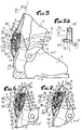
- the shoe 1 designated overall, and shown in Figures 1 to 3 is of the "front entry" type.
- This shoe 1 consists of a so-called rigid shell having a shell base 2 provided a sole 6, and surmounted by a rod 3 capable of pivoting thereon in the anteroposterior direction indicated by arrow 20, and postero-anterior indicated by arrow 21, by rotation around lateral connections 4, 4 ', preferably located in correspondence with the articulation of the wearer's ankle, not represented.
- An immobilizer 10 located on the dorsal area 5 of the rod 3 is provided with a rotary actuator 11, accessible from the outside of the boot shell, to which two movable elements 12, 13, are subject to displacement by means of a rotary cam (not represented) with which it is provided.
- Two abutment zones 14 and 15 are obtained in the heel part 16 of the shell base 2 in correspondence of the movable elements 12, 13, of the immobilization device 10. In this way, these elements 12, 13, can come to cooperate, after a displacement generated by the rotary cam, with the abutment zones 14 and 15 for at least one given angular position of the rotary cam, i.e. the operating member 11 which is provided with it.
- These abutment zones 14 and 15 are oriented so as to oppose the pivoting of the rod 3 in the antero-posterior 20 and / or postero-anterior direction 21, when the element 12 and / or 13 cooperates with.
- the rod 3 is then free to pivot with a certain amplitude, in the two posterior-anterior 21 and antero-posterior directions 20, around its connections 4, 4 ', with respect to the shell base 2.
- the shoe 1 is with a great flexibility of upper 3 which is favorable for facilitating walking and / or putting on and taking off for example.
- the abutment zone 14, covered by the dorsal zone 5 of the rod 3 is constituted by a vertical notch obtained in the heel part 16 of the shell base 2.
- This vertical notch 14, open upwards, is delimited by flexible edges 14 '.
- These are intended to reciprocally approach each other by elastic deformation, as indicated by the arrows 22, under the pushing effect of the dorsal zone 5 of the rod 3, when the said rod 3 pivots in the postero-anterior direction 21 around its connections 4, 4 ′, and when the movable element 12 is not inserted between them; it is understood that the force applied to the rod 3 must be greater than the resistant one opposed by the flexible edges 14 'to obtain a some bending.
- Lateral cutouts 17, 17 ′ can optionally be made in the base of shell 2, relatively in front of the heel part 16 thereof, in order to reduce the resistance to bending of the edges 14 ′ of the notch and therefore giving the upper 3 of the shoe a certain flexibility in the anteroposterior direction which is possible under low effort. It's obvious that the extent and shape of such lateral cutouts 17, 17 ', are provided by construction, during the definition of the structure of the hull base 2, as a function of the initial damping desired at rod level 3.
- the second stop zone 15 is located below and is presented in the form of a transverse shoulder approximately perpendicular to the notch 14.
- the second movable element 13 of the immobilizing device 10 is intended to cooperate with this shoulder 15 by bearing on it under the action of the rotary cam (not shown) of the immobilizer 10 only when the rod 3 is urged to pivot in the antero-posterior direction 20.
- FIG. 5 figure 1
- figure 6 figure 2
- figure 7 figure 3.
- the cam rotary 30 consists of a plate comprising, on each face, a probing surface 31, 32, as shown in Figure 5a. These probing surfaces 31 and 32 are mutually parallel and each have a 360 ° upper work area 33 and a lower work area 34. so, the upper 33 and lower 34 work zones are located, angularly with respect to the axis of rotation 30 '( Figure 5a) of the rotary cam 30, in the same place.
- the passage from a high work area 33 to a low work area 34 is achieved by means of a ramp progressive and angularly extends over approximately 90 °.
- the movable elements 12, 13, are each provided with a feeler 12 ', 13', and are subjected to the action of a spring 18 ensuring their permanent maintenance in contact with said surfaces 31 and 32.
- the mobile element 12 is pivotally mounted on an axis 19 passing through a part of the dorsal zone 5 of the rod 3 near the abutment zone 15, and the element mobile 12 is slidably mounted in a guide 22 obtained in said zone 5 in correspondence with the abutment zone 14 of the shell base 2.
- each 90 ° rotation of the cam 30 by means of the operation 11 causes the displacement of at least one of the movable elements 12 and 13 relative to a stop zone 14 or 15, and intrinsically modifies the immobilization and / or pivoting conditions of the rod 3 relative to the shell base 2.
- the two mobile elements 12 and 13 are used on the stop zones 14 and 15 by means of the rotary cam 30 which is placed in a position angular given allowing them to cooperate with said zones 14 and 15. More specifically, the member probing 12 ′ of the movable element 12 is in contact with the upper working area 33 of the surface of probing 32 of the cam 30 and the probing member 13 'of the movable element 13 is in contact with the area working position 34 of the probing surface 31 of the cam 30. In this position for adjusting the immobilization device 10, the rod 3 is therefore immobilized in pivoting around its connections 4, 4 ', relative to the shell base 2, whether in the antero-posterior 20 or postero-anterior direction 21.
- the upper 3 of the shoe is therefore always prevented from pivot in the antero-posterior direction 20 but able to flex in the antero-posterior direction 21 when an effort applied to it in this direction is sufficient to overcome resistance to deformation opposed to it by the flexible edges 14 ′ of the notch 14.
- the upper 3 of the shoe is then free to pivot in both directions, anteroposterior 20 and posterior anterior 21, it being understood that for bend in the direction 21 the force applied to it must be at least greater than that, resistant, than it oppose the flexible edges 14 ′ of the notch 40 on which the dorsal zone 5 of said lean rod 3.
- the plate 40 constituting the rotary cam comprises a single probing surface 41 circular having, on 360 °, two bosses 42 and 43, and the two movable elements 12, 13, are each rocker mounted on an axis 19.
- These bosses 42 and 43 in the form of arcs of a circle are provided. of the same height and different lengths, and define between them slots 44 and 45 which are symmetrically opposite with respect to the axis of rotation 40 ′ of the cam 40.
- the bosses 42 and 43 constitute the upper work area, and the slots 44 and 45 the low work area.
- the bosses 42, 43, and the slots 44, 45 are also spaced apart.
- FIGS. 8 and 8a show the immobilization device 10 in a position adjustment where the rotary cam 40 has the two slots 44 and 45, which constitute its area of low work, in cooperation with the feelers 12 ′, 13 ′, mobile elements 12 and 13.
- FIGS. 10 and 10a for another given angular position of the cam 40, these are the two bosses 42 and 43, which constitute the upper working area, which cooperate with the probing members 12 ', 13, mobile elements 12 and 13.
- Figures 9 and 9a show the cooperation a boss 43 and a slot 45 with the feelers 12 'and 13' of the movable elements 12 and 13 for yet another given angular position of the cam 40.
- FIG. 8 illustrates the immobilizer 10 in the adjustment positions which correspond to those described respectively with reference to Figures 1, 2 and 3 above.
- the upper 3 of the shoe is immobilized in both directions of pivoting 20 and 21 relative to the shell base, in FIG. 9 in the anteroposterior direction 20 only with a release in the opposite direction 21, and in FIG. 10 with a release in its two directions of pivoting 20 and 21.
- the cam 40 can be brought into an angular position where the boss 43 cooperates with the probing 13 'of element 13, and the slot 45 with the probing member 12' of element 12.
- the rod 3 is released in pivoting in the anteroposterior direction 20, and remains prevented from pivoting in the postero-anterior direction 20.
- the movable elements 12, 13, can either be provided rocked or sliding, and kept in contact with the feeler surface 31, 32, 41, of the rotary cam 30, 40, by means of a spring 18 or by any other equivalent element.
- the stop zones 14 and 15 can easily be produced by the simple arrangement of a notch 14 which is used the bottom to constitute the abutment zone 15 as shown in FIGS. 8 to 10.
Abstract
Description
La présente invention concerne une chaussure de sport dite "à coque rigide" présentant une base de coque surmontée d'une tige apte à pivoter dans les deux sens, antéro-postérieur et postéro-antérieur, et concerne un dispositif d'immobilisation par rapport à la base de coque actif pour les deux sens de pivotement de la tige par l'intermédiaire d'un organe de manoeuvre rotatif situé sur cette dernière, et se rapporte en particulier à un dispositif d'immobilisation réglable destiné à modifier la capacité de flexion de la tige dans un sens au moins, en fonction de l'usage de la chaussure envisagé à un moment.The present invention relates to a so-called "rigid shell" sports shoe having a base of shell surmounted by a rod capable of pivoting in both directions, antero-posterior and postero-anterior, and relates to an immobilization device with respect to the active shell base for both directions of pivoting of the rod by means of a rotary actuator situated on the latter, and relates in particular to an adjustable immobilization device intended to modify the capacity of bending of the upper in at least one direction, depending on the use of the shoe envisaged at a time.
Des chaussures de sport de ce type sont connues par le brevet européen EP 521 282. Selon ce document, le dispositif d'immobilisation de la tige par rapport à la base de coque est actif pour l'un au moins de ses sens de pivotement par l'intermédiaire d'une zone de butée obtenue sur la base de coque. A cet effet, le dispositif est doté d'un organe de manoeuvre rotatif muni d'une came rotative qui agit sur un élément mobile destiné, pour une position angulaire donnée de la came, à coopérer avec la zone de butée de la base de coque, et pour une autre position donnée de la came, à se dégager de ladite zone de butée. Comme cela est enseigné, lorsque l'élément mobile coopère avec la zone de butée de la base de coque, la tige de la chaussure est systématiquement bloquée vers l'arrière, c'est-à-dire contrainte à prendre une inclinaison dénommée couramment "angle d'avancée" et, simultanément, empêchée de tout pivotement vers l'avant ou libre d'un certain débattement avant blocage, déterminé par construction et résultant de l'ajustement entre la partie de l'élément mobile qui coopère avec la zone de butée et celle-ci. Inversement, lorsque l'élément mobile ne coopère pas avec la zone de butée, la tige est déverrouillée, donc libre de pivoter autant vers l'avant que vers l'arrière.Sports shoes of this type are known from European patent EP 521,282. document, the device for immobilizing the rod relative to the shell base is active for one at less of its pivoting directions via a stop zone obtained on the hull base. To this end, the device is provided with a rotary operating member provided with a rotary cam which acts on a movable element intended, for a given angular position of the cam, to cooperate with the zone abutment of the shell base, and for another given position of the cam, to disengage from said stop zone. As taught, when the movable member cooperates with the abutment area of the shell base, the upper of the shoe is systematically blocked towards the rear, i.e. constrained to take an inclination commonly called "advancing angle" and, simultaneously, prevented from pivoting forwards or free from a certain clearance before blocking, determined by construction and resulting from the adjustment between the part of the movable element which cooperates with the stop zone and this. Conversely, when the movable element does not cooperate with the stop zone, the rod is unlocked, so free to pivot as much forwards as backwards.
Comme cela apparaít clairement, le dispositif d'immobilisation décrit peut donc modifier l'aptitude à pivoter de la tige entre une position de pratique du ski, avec ou sans capacité de flexion vers l'avant selon la construction prédéterminée, et une position de marche-détente où la tige est libre de pivoter. Un tel dispositif d'immobilisation est satisfaisant si l'utilisateur s'en tient à la seule capacité de flexion vers l'avant de la tige qui est déterminé à l'avance. En fait, à partir de la position d'immobilisation de la tige dans le sens antéro-postérieur, on ne dispose que d'une position d'immobilisation dans le sens postéro-antérieur déterminant une seule capacité de flexion de ladite tige. Il demeure toutefois, selon la pratique du ski envisagé, par exemple ski de compétition ou ski de loisir-détente, ou selon l'état du manteau neigeux, neige profonde, lourde, glacée, etc..., que le skieur ait besoin d'augmenter ou de supprimer cette capacité de flexion vers l'avant. Le système d'immobilisation enseigné se révèle alors inadapté car rien ne permet, après construction, de modifier l'ajustement réalisé entre la partie de son élément mobile et la zone de butée de la base de coque, et donc la possibilité de flexion de la tige notamment vers l'avant.As is clear, the immobilization device described can therefore modify the ability to pivot the rod between a ski practice position, with or without forward bending ability according to the predetermined construction, and an on-rebound position where the rod is free to pivot. Such an immobilization device is satisfactory if the user sticks to the only flexural capacity. forward of the rod which is determined in advance. In fact, from the immobilization position of the rod in the anteroposterior direction, there is only one immobilization position in the direction postero-anterior determining a single bending capacity of said rod. However, according to the envisaged skiing, for example competition skiing or leisure-relaxation skiing, or according to the state of the snowpack, deep, heavy, icy snow, etc., that the skier needs to increase or remove this forward bending ability. The immobilization system taught then reveals itself unsuitable because nothing allows, after construction, to modify the adjustment made between the part of its mobile element and the abutment area of the shell base, and therefore the possibility of bending the rod especially forward.
Un but de la présente invention est de pallier à cet inconvénient des chaussures de sport décrites ci-avant, et propose à cet effet un dispositif d'immobilisation de la tige d'une chaussure de sport qui soit apte, pour une position angulaire donnée d'une came rotative commandée au moyen d'un organe de manoeuvre rotatif, à immobiliser la tige de la chaussure dans le sens postéro-antérieur en vue de la pratique du ski en procurant simultanément à ladite tige une certaine capacité de flexion dans le sens postéro-antérieur avant blocage, et, pour une autre position angulaire donnée de la came, garantissant toujours l'immobilisation de la tige dans le sens portéro-antérieur, en procurant simultanément à la tige une autre capacité de flexion voire même en supprimant cette dernière. En fait, l'invention fournit, pour une position d'immobilisation constante de la tige dans le sens antéro-postérieur, deux positions possibles d'immobilisation dans le sens postéro-antérieur déterminant deux capacités différentes de flexion de ladite tige.An object of the present invention is to overcome this drawback of the sports shoes described above, and for this purpose proposes a device for immobilizing the upper of a sports shoe which either suitable for a given angular position of a rotary cam controlled by means of a rotary maneuver, to immobilize the upper of the shoe in the postero-anterior direction in order to skiing while simultaneously providing said rod with a certain bending capacity in the direction postero-anterior before blocking, and, for another given angular position of the cam, always guaranteeing the immobilization of the rod in the antero-anterior direction, by providing at the same time as the rod, another capacity for bending or even eliminating the latter. In fact, the invention provides, for a position of constant immobilization of the rod in the anteroposterior direction, two possible immobilization positions in the postero-anterior direction determining two different flexural capacities of said rod.
Un autre but de l'invention est de permettre la libération de la tige en pivotement dans le sens antéro-postérieur en vue, par exemple, de faciliter la marche ou le chaussage-déchaussage, en amenant la came rotative dans au moins une position angulaire intermédiaire située entre les positions angulaires précédentes d'immobilisation de la tige, et cela en laissant à la tige une certaine capacité de flexion dans le sens postéro-antérieur.Another object of the invention is to allow the release of the rod in pivoting in the direction antero-posterior in view, for example, of facilitating walking or putting on and taking off, in bringing the rotary cam into at least one intermediate angular position situated between the positions previous angular immobilization of the rod, and this leaving the rod a certain capacity to flexion in the postero-anterior direction.
Pour atteindre ces buts, la chaussure de sport à coque rigide présente, comme dans l'état de la technique constitué par le document EP 521 282, une base de coque surmontée d'une tige apte à pivoter dans les deux sens, antéro-postérieur et postéro-antérieur, la tige étant pourvue, dans sa zone dorsale, d'un dispositif d'immobilisation par rapport à la base de coque actif pour l'un au moins de ses sens de pivotement, par l'intermédiaire d'une zone de butée obtenue sur ladite base de coque. Le dispositif d'immobilisation est doté d'un organe de manoeuvre muni d'une came rotative qui agit sur un élément mobile destiné à coopérer, pour une position angulaire donnée de la came, avec la zone de butée de la base de coque.To achieve these goals, the rigid shell sports shoe has, as in the state of the technique constituted by document EP 521 282, a shell base surmounted by a rod capable of pivot in both directions, antero-posterior and postero-anterior, the rod being provided in its zone dorsal, of an immobilization device with respect to the active shell base for at least one of its pivoting direction, via a stop zone obtained on said shell base. The immobilizer is provided with an operating member provided with a rotary cam which acts on a movable element intended to cooperate, for a given angular position of the cam, with the area of hull base stop.
La chaussure de sport se caractérise par le fait que le dispositif d'immobilisation comporte un deuxième élément mobile qui est actionnable au moyen de la came rotative et qui est destiné à coopérer avec une deuxième zone de butée obtenue sur la base de coque pour au moins une position angulaire donnée de la came. La coopération de ce deuxième élément mobile avec cette deuxième zone de butée est destinée à procurer l'immobilisation de la tige pour l'un de ses deux sens de pivotement, tandis que la coopération du premier élément mobile avec la première zone de butée procure l'immobilisation de la tige pour l'autre de ses deux sens de pivotement.The sports shoe is characterized by the fact that the immobilization device comprises a second mobile element which is actuable by means of the rotary cam and which is intended for cooperate with a second stop zone obtained on the shell base for at least one position given angularity of the cam. The cooperation of this second mobile element with this second zone stop is intended to provide immobilization of the rod for one of its two directions of pivoting, while the cooperation of the first movable element with the first stop zone provides immobilization of the rod for the other of its two directions of pivoting.
La mise en oeuvre simultanée des deux éléments mobiles avec les deux zones de butée provoque ainsi l'immobilisation de la tige de la chaussure dans les deux sens de pivotement et la mise en oeuvre d'un seul élément mobile avec sa zone de butée provoque seulement l'immobilisation de la tige dans un sens de pivotement. Inversement, le désengagement simultané, ou l'escamotage, des deux éléments mobiles provoque la libération de la tige dans ses deux sens de pivotement, tandis que le désengagement de l'un des éléments mobile provoque seulement la libération de la tige dans un sens de pivotement.The simultaneous implementation of the two movable elements with the two stop zones causes thus immobilizing the upper of the shoe in both directions of pivoting and implementing of a single mobile element with its stop zone only causes the immobilization of the rod in a pivoting direction. Conversely, the simultaneous disengagement, or retraction, of the two elements moving causes the rod to be released in both directions of pivoting, while the disengagement of one of the movable elements only causes the release of the rod in a direction of pivoting.
On dispose ainsi d'au moins trois possibilités de modification de l'aptitude à pivoter de sa tige, ce qui permet d'optimiser le rôle de la chaussure notamment lorsque lui sont assujettis des matériels ou accessoires nécessaires à la pratique sportive tels que skis, patins, crampons, etc..., modifiant la gestuelle traditionnelle de la marche ou de la course.There are thus at least three possibilities for modifying the ability to pivot of its rod, which optimizes the role of the shoe, especially when it is subject to equipment or accessories necessary for sports such as skis, skates, crampons, etc., modifying the traditional gestures of walking or running.
Selon une caractéristique, la came rotative du dispositif d'immobilisation est constituée par un plateau qui, axé sur l'organe de manoeuvre, comporte au moins une surface de palpage circulaire présentant une zone de travail haute et une zone de travail basse, et les deux éléments mobiles du dispositif coopèrent avec cette surface de palpage par l'intermédiaire d'un organe de palpage dont ils sont pourvus respectivement.According to one characteristic, the rotary cam of the immobilization device is constituted by a plate which, centered on the operating member, comprises at least one circular probing surface having a high working area and a low working area, and the two movable elements of the device cooperate with this feeler surface by means of a feeler member of which they are provided respectively.
Selon une autre caractéristique, les organes de palpage des éléments mobiles viennent au contact de la surface de palpage de la came à distance l'un de l'autre, chacun sur l'une des zones de travail haute et basse, en des points opposés par rapport à l'axe de rotation de l'organe de manoeuvre.According to another characteristic, the feelers of the mobile elements come into contact of the probing surface of the cam at a distance from each other, each on one of the working zones high and low, at opposite points relative to the axis of rotation of the operating member.
Selon un mode de réalisation du dispositif d'immobilisation, le plateau constituant la came rotative comporte deux surfaces de palpage, soit une sur chaque face, parallèles entre elles, et présentant, chacune, une zone de travail haute et une zone de travail basse, chaque élément mobile venant coopérer avec l'une des deux surfaces de palpage par l'intermédiaire de son organe de palpage.According to one embodiment of the immobilization device, the plate constituting the rotary cam has two probing surfaces, one on each side, parallel to each other, and having, each, a high work area and a low work area, each moving element coming cooperate with one of the two probing surfaces by means of its probing member.
Selon un autre mode de réalisation du dispositif d'immobilisation, le plateau constituant la came rotative comporte une seule surface de palpage présentant, sur 360°, deux bossages en forme d'arcs de cercle de même hauteur et de longueurs différentes définissant entre eux deux créneaux qui leur sont symétriquement opposés par rapport à l'axe de rotation de la came et donc de l'organe de manoeuvre, les bossages constituant la zone de travail haute et les créneaux la zone de travail basse.According to another embodiment of the immobilization device, the plate constituting the cam rotary has a single probing surface having, on 360 °, two bosses in the form of arcs of circle of the same height and different lengths defining between them two slots which their are symmetrically opposite with respect to the axis of rotation of the cam and therefore of the maneuver, the bosses constituting the upper work area and the slots the work area low.
Selon une caractéristique préférée de l'invention, les deux zones de butée de la base de coque sont obtenues et situées dans la partie talon de celle-ci, chaque zone de butée étant destinée à assurer, en coopération avec un des deux éléments mobiles du dispositif d'immobilisation et pour au moins une position angulaire donnée de la came rotative, l'immobilisation de la tige dans un de ses sens de pivotement.According to a preferred characteristic of the invention, the two abutment zones of the shell base are obtained and located in the heel part thereof, each stop zone being intended to ensure, in cooperation with one of the two movable elements of the immobilizer and for at least one given angular position of the rotary cam, immobilization of the rod in one of its directions pivoting.
Selon un mode de réalisation, les deux zones de butée de la base de coque sont constituées, l'une par une échancrure verticale ouverte vers le haut et délimitée par des bords flexibles pour son immobilisation portéro-antérieure, et l'autre par son épaulement pour son immobilisation antéro-postérieure.According to one embodiment, the two abutment zones of the shell base are formed, one by a vertical notch open upwards and delimited by flexible edges for its porto-anterior immobilization, and the other by its shoulder for its antero-posterior immobilization.
Dans ce mode de réalisation, la zone de butée constituée par l'échancrure est située au-dessus de celle constituée par l'épaulement. Elle est recouverte par la zone dorsale de la tige et est destinée à coopérer avec un des éléments mobiles qui peut, au choix, sous l'action de la came rotative et pour des positions angulaires déterminées de celle-ci, s'escamoter de ladite échancrure ou s'insérer entre ses bords flexibles procurant par là même une certaine possibilité de pivotement postéro-antérieur de la tige ou son immobilisation dans ce sens. En effet, lorsque l'élément mobile du dispositif d'immobilisation est escamoté de l'échancrure, les bords flexibles de cette dernière peuvent se rapprocher l'un de l'autre par déformation élastique sous l'effet de poussée de la zone dorsale de la tige qui la recouvre et qui décrit une trajectoire engageante sur la partie talon de la base de coque à l'endroit de ladite échancrure. Il est bien entendu que cette possibilité de pivotement n'est permise que lorsque l'effort de flexion appliqué sur la tige est supérieur à celui, résistant, que lui opposent les bords flexibles de l'échancrure. Dans l'autre position de l'élément mobile, c'est-à-dire lorsque ce dernier coopère avec l'échancrure en s'insérant entre ses bords flexibles sous l'action de la came rotative, pour une autre position angulaire donnée de celle-ci, les bords flexibles se trouvent empêchés de tout rapprochement réciproque puisqu'ils butent sur l'élément mobile ; par voie de conséquence, les bords flexibles de l'échancrure s'opposent à la poussée de la zone dorsale de la tige qui ne peut plus décrire sa trajectoire engageante sur eux. L'échancrure constitue ainsi la zone de butée de la base de coque capable d'immobiliser la tige dans le sens postéro-antérieur, et, selon la position angulaire donnée à la came rotative au moyen de l'organe de manoeuvre, la zone de butée également susceptible d'autoriser une certaine possibilité de flexion de la tige dans le sens postéro-antérieur.In this embodiment, the abutment zone formed by the notch is located above that formed by the shoulder. It is covered by the dorsal area of the stem and is intended for cooperate with one of the movable elements which can, as desired, under the action of the rotary cam and for determined angular positions thereof, to retract from said notch or to be inserted between its flexible edges thereby providing a certain possibility of postero-anterior pivoting of the rod or its immobilization in this direction. When the mobile element of the device is retracted from the notch, the flexible edges of the latter can be bring them closer to each other by elastic deformation under the pushing effect of the dorsal area of the rod which covers it and which describes an engaging trajectory on the heel part of the hull base to the place of said notch. It is understood that this possibility of pivoting is only permitted when the bending force applied to the rod is greater than that, resistant, opposed to it by the edges flexible notches. In the other position of the movable element, that is to say when the latter cooperates with the notch by being inserted between its flexible edges under the action of the rotary cam, for another given angular position thereof, the flexible edges are prevented from any reciprocal rapprochement since they run into the mobile element; as a result, the edges flexible notches oppose the thrust of the dorsal area of the rod which can no longer describe its engaging trajectory on them. The notch thus constitutes the abutment zone of the shell base capable of immobilizing the rod in the postero-anterior direction, and, depending on the angular position given to the rotary cam by means of the operating member, the abutment zone also capable of authorizing some possibility of bending of the rod in the postero-anterior direction.
Relativement à l'échancrure, l'épaulement constituant la deuxième zone de butée est situé endessous et transversalement à cette dernière, également sur la partie talon de la base de coque, et c'est le deuxième élément mobile du dispositif d'immobilisation, c'est-à-dire celui non associe fonctionnellement avec l'échancrure, qui est destiné à coopérer avec. Selon une structure préférée, cet élément mobile prend appui sur l'épaulement sous l'action de la came rotative, pour une position angulaire donnée de celle-ci, et notamment lorsque la tige est sollicitée à fléchir dans le sens antéro-postérieur.Relative to the notch, the shoulder constituting the second stop zone is located below and transversely to the latter, also on the heel part of the shell base, and it is the second movable element of the immobilization device, that is to say the one not associated functionally with the notch, which is intended to cooperate with. According to a preferred structure, this movable element bears on the shoulder under the action of the rotary cam, for a position angular given thereof, and in particular when the rod is urged to bend in the antero-posterior direction.
L'invention sera du reste mieux comprise, ainsi que certaines caractéristiques, en se reportant à la description qui suit en référence aux dessins schématiques annexés montrant, à titres d'exemples, deux modes de réalisation typiques et selon lesquels :
- les figures 1, 2 et 3 illustrent trois positions de réglage d'une dispositif d'immobilisation selon l'invention et son action sur les possibilités de pivotement de la tige de la chaussure dans les sens antéro-postérieur et postéro-antérieur,
- la figure 4 montre, schématiquement, un détail de réalisation des deux zones de butée réalisées dans la partie talon de la base de coque de la chaussure des figure 1 à 3,
- les figures 5, 6 et 7 représentent la chaussure de la figure 1 vue en coupe partielle suivant la ligne V-V, et montrent, respectivement, selon un premier mode de réalisation de l'invention, un dispositif d'immobilisation dans chacune de ses trois positions de réglage des figures 1, 2 et 3,
- la figure 5a montre un détail de réalisation de la came rotative du dispositif d'immobilisation de la figure 5,
- les figures 8, 9 et 10 illustrent un autre dispositif d'immobilisation de la tige de la chaussure de la figure 1 vue en coupe partielle suivant la ligne V-V selon un deuxième mode de réalisation de l'invention, dans trois positions de réglage correspondantes à celles des figures 1, 2 et 3,
- la figure 11 représente, vue en perspective, l'extrémité ou plateau de la came rotative du dispositif d'immobilisation de la figure 8 mettant en évidence sa zone de palpage,
- les figures 8a, 9a et 10a illustrent, vue en plan, la position de la zone de palpage de la came rotative pour chacune des trois positions de réglage du dispositif d'immobilisation des figures 8, 9 et 10.
- FIGS. 1, 2 and 3 illustrate three adjustment positions of an immobilization device according to the invention and its action on the possibilities of pivoting of the upper of the shoe in the antero-posterior and postero-anterior directions,
- FIG. 4 schematically shows a detail of the two abutment zones produced in the heel part of the shell base of the shoe of FIGS. 1 to 3,
- Figures 5, 6 and 7 show the shoe of Figure 1 viewed in partial section along the line VV, and show, respectively, according to a first embodiment of the invention, an immobilization device in each of its three positions for adjusting Figures 1, 2 and 3,
- FIG. 5a shows a detail of the embodiment of the rotary cam of the immobilization device of FIG. 5,
- Figures 8, 9 and 10 illustrate another device for immobilizing the upper of the shoe of Figure 1 viewed in partial section along the line VV according to a second embodiment of the invention, in three adjustment positions corresponding to those of FIGS. 1, 2 and 3,
- FIG. 11 shows, in perspective view, the end or plate of the rotary cam of the immobilization device of FIG. 8 showing its probing zone,
- FIGS. 8a, 9a and 10a illustrate, in plan view, the position of the probing zone of the rotary cam for each of the three adjustment positions of the immobilization device of FIGS. 8, 9 and 10.
A titre d'exemple illustratif, non limitatif, la chaussure 1 désignée globalement, et représentée aux
figures 1 à 3, est de type à "entrée par l'avant".By way of illustrative, nonlimiting example, the
Cette chaussure 1 est constituée d'une coque dite rigide présentant une base de coque 2 munie
d'une semelle 6, et surmontée d'une tige 3 apte à pivoter dessus dans le sens antéro-postérieur indiqué
par la flèche 20, et postéro-antérieur indiqué par la flèche 21, par rotation autour de liaisons latérales
4, 4', situées de préférence en correspondance de l'articulation de la cheville du porteur, non
représentée. Un dispositif d'immobilisation 10 situé sur la zone dorsale 5 de la tige 3 est muni d'un
organe de manoeuvre rotatif 11, accessible de l'extérieur de la coque de la chaussure, auquel deux
éléments mobiles 12, 13, sont assujettis en déplacement par l'intermédiaire d'une came rotative (non
représentée) dont il est pourvu.This
Deux zones de butée 14 et 15 sont obtenues dans la partie talon 16 de la base de coque 2 en
correspondance des éléments mobiles 12, 13, du dispositif d'immobilisation 10. De la sorte, ces
éléments 12, 13, peuvent venir coopérer, après un déplacement généré par la came rotative, avec les
zones de butée 14 et 15 pour au moins une position angulaire donnée de la came rotative, soit de
l'organe de manoeuvre 11 qui en est pourvu. Ces zones de butée 14 et 15 sont orientées de façon à
s'opposer au pivotement de la tige 3 dans le sens antéro-postérieur 20 et/ou postéro-antérieur 21,
lorsque l'élément 12 et/ou 13 coopère avec. En fait, lorsque les deux éléments 12 et 13 sont mis en
oeuvre sur les zones de butée 14 et 15, la tige 3 de la chaussure est immobilisée dans les deux sens de
pivotement 20 et 21 comme représenté à la figure 1. On dispose alors d'une chaussure "raide" car sa
tige 3 n'a pratiquement pas de degré de liberté en pivotement. Il résulte de cette immobilisation que les
efforts et sollicitations, intervenants entre la jambe du porteur et la semelle 6 de la chaussure et/ou le
matériel ou accessoire de sport assujetti à la chaussure 1, sont transmis quasi instantanément de la
tige 3 à la semelle 4 et inversement. Un tel comportement de la chaussure 1 est particulièrement
avantageux lorsque le porteur doit faire preuve de réactivité, par exemple lorsqu'il pratique la
compétition, car la raideur ainsi conférée à la tige 3 lui permet de ressentir les moindres variations de
ses appuis et donc de réagir en conséquent.Two
Dans une autre position, représentée à la figure 2, seul l'élément mobile 13 coopère avec la zone de
butée 15. La tige 3 reste alors immobilisée dans le sens antéro-postérieur 20 mais est capable d'une
certaine flexion dans le sens postéro-antérieur avant blocage par appui de sa bordure antérieure 3'
sur la base de coque 2 dans la zone correspondant au cou-de-pied. On dispose dans ce cas d'une
chaussure "raide" dans le sens antéro-postérieur 20 et relativement souple dans le sens postéro-antérieur
21, ce qui est souvent recherché lors de pratiques sportives exigeant moins de réactivité de
la part du porteur ou encore lorsque ce dernier souhaite avoir un certain degré de liberté de flexion
dans le sens postéro-antérieur 21.In another position, shown in Figure 2, only the
Encore, comme illustré à la figure 3, lorsque les deux éléments mobiles 12 et 13 sont escamotés
des zones de butée 14 et 15, la tige 3 est alors libre de pivoter avec une certaine amplitude, dans les
deux sens postéro-antérieur 21 et antéro-postérieur 20, autour de ses liaisons 4, 4', par rapport à la
base de coque 2. Dans ce cas de réglage du dispositif d'immobilisation 10, la chaussure 1 se trouve
dotée d'une grande flexibilité de tige 3 ce qui est favorable pour faciliter la marche et/ou le chaussage-déchaussage
par exemple.Again, as illustrated in Figure 3, when the two
Selon un mode de construction préféré illustré à la figure 4, la zone de butée 14, recouverte par la
zone dorsale 5 de la tige 3 (non illustrée), est constituée par une échancrure verticale obtenue dans la
partie talon 16 de la base de coque 2. Cette échancrure verticale 14, ouverte vers le haut, est
délimitée par des bords flexibles 14'. Ceux-ci sont destinés à se rapprocher réciproquement par
déformation élastique, tel qu'indiqué par les flèches 22, sous l'effet de poussée de la zone dorsale 5 de
la tige 3, lorsque ladite tige 3 pivote dans le sens postéro-antérieur 21 autour de ses liaisons 4, 4', et
lorsque l'élément mobile 12 n'est pas inséré entre eux ; il est bien entendu que l'effort appliqué sur la
tige 3 doit être supérieur à celui résistant que lui opposent les bords flexibles 14' pour obtenir une
certaine flexion. Des découpes latérales 17, 17', peuvent éventuellement être réalisées dans la base de
coque 2, relativement en avant de la partie talon 16 de celle-ci, afin de diminuer la résistance à la
flexion des bords 14' de l'échancrure et donc de conférer à la tige 3 de la chaussure une certaine
flexibilité dans le sens antéro-postérieur 20 qui soit possible sous un effort faible. Il est évident que
l'étendue et la forme de telles découpes latérales 17, 17', sont prévues par construction, lors de la
définition de la structure de la base de coque 2, en fonction de l'amortissement initial souhaité au
niveau de la tige 3.According to a preferred construction method illustrated in FIG. 4, the
Dans la position d'engagement de l'élément mobile 12 entre les bords flexibles 14' de l'échancrure 14
sous l'action de la came rotative (non représentée) du dispositif d'immobilisation 10, la poussée
exercée par la zone dorsale 5 de la tige 3 ne peut plus générer le rapprochement des bords 14', et c'est
donc la partie talon 16 de la base de coque 2 qui s'oppose globalement à la flexion de la tige 3 dans le
sens postéro-antérieur 21. En fait, dans cette position de l'élément mobile 12, on obtient quasiment un
blocage de la tige 3, soit son immobilisation vers l'avant.In the position of engagement of the
Relativement à l'échancrure 14, la deuxième zone de butée 15 est située en-dessous et se présente
sous la forme d'un épaulement transversal approximativement perpendiculaire à l'échancrure 14. Le
deuxième élément mobile 13 du dispositif d'immobilisation 10 est destiné à coopérer avec cet
épaulement 15 en prenant appui dessus sous l'action de la came rotative (non représentée) du
dispositif d'immobilisation 10 seulement lorsque la tige 3 est sollicitée à pivoter dans le sens antéro-postérieur
20.Relative to the
De ce fait, quelle que soit la position de l'élément mobile 13, c'est-à-dire en position de coopération
avec la zone de butée 14 ou en position escamotée, les possibilités de flexion de la tige 3 dans le sens
postéro-antérieur 21 restent essentiellement déterminées par la position donnée à l'élément mobile 12.Therefore, whatever the position of the
Les figures 5, 6 et 7 qui suivent montrent un mode de réalisation du dispositif d'immobilisation 10 de
la chaussure 1 dans les trois positions de réglage précédemment décrites, soit respectivement : figure
5 = figure 1, figure 6 = figure 2, figure 7 = figure 3. Dans cette construction du dispositif 10, la came
rotative 30 est constituée d'un plateau comportant, sur chaque face, une surface de palpage 31, 32,
tel qu'illustré sur la figure 5a. Ces surfaces de palpage 31 et 32 sont parallèles entre elles et
présentent, chacune sur 360°, une zone de travail haute 33 et une zone de travail basse 34. De la
sorte, les zones de travail hautes 33 et basses 34 se trouvent situées, angulairement par rapport à
l'axe de rotation 30' (figure 5a) de la came rotative 30, au même endroit. Par ailleurs, le passage
d'une zone de travail haute 33 à une zone de travail basse 34 est réalisé au moyen d'une rampe
progressive et s'étend angulairement sur environ 90°. Pour coopérer avec chaque surface de palpage
31 et 32, les éléments mobiles 12, 13, sont dotés, chacun, d'un organe de palpage 12', 13', et sont
soumis à l'action d'un ressort 18 assurant leur maintien permanent au contact desdites surfaces 31 et
32. Dans cet exemple de construction, l'élément mobile 12 est monté pivotant sur un axe 19
traversant une partie de la zone dorsale 5 de la tige 3 à proximité de la zone de butée 15, et l'élément
mobile 12 est monté coulissant dans un guidage 22 obtenu dans ladite zone 5 en correspondance de la
zone de butée 14 de la base de coque 2. Ce montage en vis à vis des zones de butée 14 et 15 fait que
les éléments mobiles 12 et 13 avec leurs organes de palpage 12', 13', se trouvent placés angulairement
à 180° l'un de l'autre par rapport à l'axe de rotation 30' de la came 30. Par conséquence, à partir
d'une position angulaire donnée, chaque rotation à 90° de la came 30 au moyen de l'organe de
manoeuvre 11 provoque le déplacement d'au moins un des éléments mobiles 12 et 13 par rapport à une
zone de butée 14 ou 15, et modifie intrinsèquement les conditions d'immobilisation et/ou de pivotement
de la tige 3 par rapport à la base de coque 2.Figures 5, 6 and 7 which follow show an embodiment of the
Par exemple, tel qu'illustré à la figure 5, les deux éléments mobiles 12 et 13 son mis en oeuvre sur
les zones de butée 14 et 15 par l'intermédiaire de la came rotative 30 qui est placée dans une position
angulaire donnée leur permettant de coopérer avec lesdites zones 14 et 15. Plus précisément, l'organe
de palpage 12' de l'élément mobile 12 est au contact de la zone de travail haute 33 de la surface de
palpage 32 de la came 30 et l'organe de palpage 13' de l'élément mobile 13 est au contact de la zone
de travail basse 34 de la surface de palpage 31 de la came 30. Dans cette position de réglage du
dispositif d'immobilisation 10, la tige 3 se trouve donc immobilisée en pivotement autour de ses liaisons
4, 4', par rapport à la base de coque 2, que ce soit dans le sens antéro-postérieur 20 ou postéro-antérieur
21.For example, as illustrated in FIG. 5, the two
A partir de cette position angulaire donnée à la came 30, une rotation à 90° de l'organe de
manoeuvre 11 du dispositif d'immobilisation 10, et donc de la came 30, comme cela est représenté à la
figure 6, provoque seulement le retrait de l'élément mobile 12 par rapport à sa zone de butée 14 soit de
l'échancrure. En effet, la came 30 présente alors, en vis à vis de l'organe de palpage 12' de l'élément
12, sa zone de travail basse 34 qui, relativement à la zone de butée 14 de la base de coque 2, est plus
éloignée que sa zone de travail haute 33. Par contre, en vis à vis de l'organe de palpage 13' de
l'élément 13, c'est toujours sa zone de travail basse 34 qui est au contact. Dans cette position de
réglage du dispositif d'immobilisation 10, la tige 3 de la chaussure est donc toujours empêchée de
pivoter dans le sens antéro-postérieur 20 mais apte à fléchir dans le sens antéro-postérieur 21
lorsqu'un effort qui lui est appliqué dans ce sens est suffisant pour vaincre la résistance à la
déformation que lui opposent les bords flexibles 14' de l'échancrure 14.From this angular position given to the
Encore, figure 7, par une nouvelle rotation à 90° de la came 30 à partir de sa position précédente
illustrée à la figure 6, et en respectant le même sens de manoeuvre, l'élément mobile 13 s'escamote à
son tour de sa zone de butée 15. En effet, dans cette position angulaire de la came 30, c'est avec la
zone de travail haute 33 de la surface de palpage 32 que vient coopérer l'organe de palpage 13' de
l'élément 13. Cette zone de travail haute 33 étant plus rapprochée que celle basse 34 relativement à
la zone de butée 15, elle contraint l'élément mobile 13 à basculer d'autant, sur son axe 19 par son
organe de palpage 13' interposé, et ainsi à s'escamoter que ladite zone de butée 15. Dans cette autre
position de réglage du dispositif d'immobilisation 10, la tige 3 de la chaussure se trouve alors libre de
pivoter dans les deux sens, antéro-postérieur 20 et postéro-antérieur 21, étant entendu que pour
fléchir selon le sens 21 l'effort qui lui est appliqué doit être au moins supérieur à celui, résistant, que lui
opposent les bords flexibles 14' de l'échancrure 40 sur lesquels s'appuie la zone dorsale 5 de ladite
tige 3. Again, Figure 7, by a further 90 ° rotation of the
Selon un autre mode de réalisation du dispositif d'immobilisation 10, représenté sur les figures 8 à
11 qui suivent, le plateau 40 constituant la came rotative comporte une seule surface de palpage 41
circulaire présentant, sur 360°, deux bossages 42 et 43, et les deux éléments mobiles 12, 13, sont
montés à bascule chacun sur un axe 19. Ces bossages 42 et 43 en forme d'arcs de cercle sont prévus
de même hauteur et de longueurs différentes, et définissent entre eux des créneaux 44 et 45 qui leur
sont symétriquement opposés par rapport à l'axe de rotation 40' de la came 40. Dans ce cas de
construction, les bossages 42 et 43 constituent la zone de travail haute, et les créneaux 44 et 45 la
zone de travail basse. Les bossages 42, 43, et les créneaux 44, 45, sont par ailleurs espacés
angulairement les uns des autres de sorte qu'ils peuvent agir, pour une position angulaire donnée de la
came 40 au moyen de l'organe de manoeuvre 11, sur les organes de palpage 12' et 13' des deux
éléments mobiles 12 et 13, soit deux par deux 42 et 43 ou 44 et 45, soit un bossage 42 ou 43 avec un
créneau 44 ou 45.According to another embodiment of the
A titre d'exemple, les figures 8 et 8a représentent le dispositif d'immobilisation 10 dans une position
de réglage où la came rotative 40 présente les deux créneaux 44 et 45, qui constituent sa zone de
travail basse, en coopération avec les organes de palpage 12', 13', des éléments mobiles 12 et 13.
Dans les figures 10 et 10a, pour une autre position angulaire donnée de la came 40, ce sont les deux
bossages 42 et 43, qui constituent la zone de travail haute, qui coopèrent avec les organes de palpage
12', 13, des éléments mobiles 12 et 13. Comparativement, les figures 9 et 9a montrent la coopération
d'un bossage 43 et d'un créneau 45 avec les organes de palpage 12' et 13' des éléments mobiles 12 et
13 pour encore une autre position angulaire donnée de la came 40.By way of example, FIGS. 8 and 8a show the
Comme cela est représenté, les figures 8, 9 et 10, illustrent le dispositif d'immobilisation 10 dans les
positions de réglage qui correspondent à celles décrites respectivement en référence aux figures 1, 2
et 3 qui précèdent. Ainsi, en figure 8 la tige 3 de la chaussure est immobilisée dans les deux sens de
pivotement 20 et 21 par rapport à la base de coque, en figure 9 dans le sens antéro-postérieur 20
seulement avec une libération dans le sens opposé 21, et en figure 10 avec une libération dans ses
deux sens de pivotement 20 et 21. D'autres positions de réglage sont cependant possibles. En effet, la
came 40 peut être amenée dans une position angulaire où le bossage 43 coopère avec l'organe de
palpage 13' de l'élément 13, et le créneau 45 avec l'organe de palpage 12' de l'élément 12. Dans ce cas,
la tige 3 est libérée en pivotement dans le sens antéro-postérieur 20, et reste empêchée de pivoter
dans le sens postéro-antérieur 20.As shown, Figures 8, 9 and 10 illustrate the
Il est bien entendu que les moyens constitutifs du dispositif d'immobilisation 10 et/ou les zones de
butées 14 et 15 peuvent être réalisés de manière différente sans pour cela sortir du cadre de
l'invention.It is understood that the means constituting the
Ainsi, les éléments mobiles 12, 13, peuvent indifféremment être prévus montés à bascule ou
coulissants, et maintenus au contact de la surface de palpage 31, 32, 41, de la came rotative 30, 40,
au moyen d'un ressort 18 ou au moyen de tout autre élément équivalent. Encore, les zones de butées
14 et 15 peuvent aisément être réalisées par le seul aménagement d'une échancrure 14 dont on utilise
le fond pour constituer la zone de butée 15 comme représenté aux figures 8 à 10.Thus, the
Claims (10)
Applications Claiming Priority (2)
| Application Number | Priority Date | Filing Date | Title |
|---|---|---|---|
| FR9610873 | 1996-09-04 | ||
| FR9610873A FR2752684B1 (en) | 1996-09-04 | 1996-09-04 | SPORTS SHOE EQUIPPED WITH AN IMMOBILIZING DEVICE IN PIVOTING THE UPPER |
Publications (1)
| Publication Number | Publication Date |
|---|---|
| EP0827700A1 true EP0827700A1 (en) | 1998-03-11 |
Family
ID=9495503
Family Applications (1)
| Application Number | Title | Priority Date | Filing Date |
|---|---|---|---|
| EP97113364A Ceased EP0827700A1 (en) | 1996-09-04 | 1997-08-02 | Sportsshoe with a device for the immobilisation of the pivoting of the cuff |
Country Status (4)
| Country | Link |
|---|---|
| US (1) | US5857271A (en) |
| EP (1) | EP0827700A1 (en) |
| JP (1) | JPH1085001A (en) |
| FR (1) | FR2752684B1 (en) |
Cited By (3)
| Publication number | Priority date | Publication date | Assignee | Title |
|---|---|---|---|---|
| EP2898788A1 (en) * | 2014-01-24 | 2015-07-29 | Salomon S.A.S. | Sports shoe |
| US9241532B2 (en) | 2012-01-04 | 2016-01-26 | K-2 Corporation | Ski/walk mechanism |
| IT202000000988A1 (en) * | 2020-01-20 | 2021-07-20 | Tecnica Group Spa | Ski boot, especially ski touring boot |
Families Citing this family (10)
| Publication number | Priority date | Publication date | Assignee | Title |
|---|---|---|---|---|
| US6231066B1 (en) | 1999-03-03 | 2001-05-15 | Shimano Inc. | Active highback system for a snowboard boot |
| FR2793391B1 (en) * | 1999-05-12 | 2001-06-08 | Salomon Sa | CROSS COUNTRY SKI SHOE |
| FR2819692B1 (en) * | 2001-01-24 | 2003-05-02 | Salomon Sa | SPORTS SHOE, ESPECIALLY FOR SKIING, PROVIDED WITH AN AUTOMATIC STEERING DEVICE FOR PIVOTING THE ROD |
| FR2924904B1 (en) * | 2007-12-14 | 2010-01-01 | Salomon Sa | SPORT SHOE WITH LOCKING DEVICE |
| AT512080B1 (en) * | 2011-11-02 | 2013-07-15 | Fischer Sports Gmbh | BOOT |
| EP3090641B1 (en) * | 2015-05-06 | 2021-12-01 | OBER ALP S.p.A. | Ski boot provided with an improved ski-walk selection mechanism |
| CA197133S (en) | 2020-07-27 | 2022-05-12 | Dentec Safety Specialists Inc | Mid-sole traction device |
| CA197134S (en) | 2020-07-27 | 2022-05-12 | Dentec Safety Specialists Inc | Heel traction device |
| CA3088629A1 (en) | 2020-07-31 | 2022-01-31 | Dentec Safety Specialists Inc. | Mid-sole traction device |
| CA3088637A1 (en) | 2020-07-31 | 2022-01-31 | Dentec Safety Specialists Inc. | Heel traction device |
Citations (3)
| Publication number | Priority date | Publication date | Assignee | Title |
|---|---|---|---|---|
| EP0521282A1 (en) * | 1991-07-01 | 1993-01-07 | Salomon S.A. | Skiboot with pivot locking device of the upper quarter |
| EP0521283A1 (en) * | 1991-07-01 | 1993-01-07 | Salomon S.A. | Skiboot with locking device of the upper quarter |
| EP0582803A1 (en) * | 1992-08-11 | 1994-02-16 | Salomon S.A. | Skiboot |
-
1996
- 1996-09-04 FR FR9610873A patent/FR2752684B1/en not_active Expired - Fee Related
-
1997
- 1997-08-02 EP EP97113364A patent/EP0827700A1/en not_active Ceased
- 1997-09-03 US US08/922,361 patent/US5857271A/en not_active Expired - Fee Related
- 1997-09-04 JP JP9239561A patent/JPH1085001A/en active Pending
Patent Citations (3)
| Publication number | Priority date | Publication date | Assignee | Title |
|---|---|---|---|---|
| EP0521282A1 (en) * | 1991-07-01 | 1993-01-07 | Salomon S.A. | Skiboot with pivot locking device of the upper quarter |
| EP0521283A1 (en) * | 1991-07-01 | 1993-01-07 | Salomon S.A. | Skiboot with locking device of the upper quarter |
| EP0582803A1 (en) * | 1992-08-11 | 1994-02-16 | Salomon S.A. | Skiboot |
Cited By (5)
| Publication number | Priority date | Publication date | Assignee | Title |
|---|---|---|---|---|
| US9241532B2 (en) | 2012-01-04 | 2016-01-26 | K-2 Corporation | Ski/walk mechanism |
| EP2898788A1 (en) * | 2014-01-24 | 2015-07-29 | Salomon S.A.S. | Sports shoe |
| FR3016775A1 (en) * | 2014-01-24 | 2015-07-31 | Salomon Sas | SPORTS SHOE |
| IT202000000988A1 (en) * | 2020-01-20 | 2021-07-20 | Tecnica Group Spa | Ski boot, especially ski touring boot |
| EP3850978A1 (en) * | 2020-01-20 | 2021-07-21 | Tecnica Group S.p.A. | Ski boot, more particularly boot for ski mountaineering |
Also Published As
| Publication number | Publication date |
|---|---|
| JPH1085001A (en) | 1998-04-07 |
| FR2752684B1 (en) | 1998-10-30 |
| FR2752684A1 (en) | 1998-03-06 |
| US5857271A (en) | 1999-01-12 |
Similar Documents
| Publication | Publication Date | Title |
|---|---|---|
| EP0088673B1 (en) | Device for cross-country-ski | |
| EP0679416A1 (en) | Binding for a skiing device | |
| EP0827700A1 (en) | Sportsshoe with a device for the immobilisation of the pivoting of the cuff | |
| FR2471795A1 (en) | STOP-FRONT OF SKI FIXING | |
| EP0913102B1 (en) | Sole for sportsshoe | |
| WO1996032992A1 (en) | Safety binding for telemark, cross-country and ski-jumping skis | |
| FR2642980A1 (en) | Binding device for a cross-country ski and boot intended for such a binding device | |
| EP1108450B1 (en) | Device for retaining a shoe on a gliding board | |
| FR2748214A1 (en) | DEVICE FOR RETAINING A SHOE ON A SLIDING BOARD INTENDED FOR SURFING PRACTICE | |
| WO1996036407A1 (en) | Device for holding a boot on a snowboard | |
| EP0726036B1 (en) | Shoe with controlled flex | |
| FR2745474A1 (en) | SPORTS SHOE | |
| CH664264A5 (en) | SKI BOOT. | |
| EP1104251B1 (en) | Cross-country ski boot | |
| CH673776A5 (en) | ||
| FR2497110A1 (en) | FRONT JACKET FOR SKI SAFETY FASTENING | |
| EP0648439B1 (en) | Ski boot | |
| EP3741436A1 (en) | Binding device for fixing a boot onto a snowboard | |
| EP0820789B1 (en) | Boot-ski combination | |
| WO1991008807A1 (en) | Safety binding for skis | |
| EP0692203A1 (en) | Sportshoe, in particular skiboot | |
| EP0436444B1 (en) | Plastic ski boot | |
| EP2959949B1 (en) | Device for accommodating a shoe on a snow gliding device | |
| EP0823222A1 (en) | Sports shoe | |
| EP0667174A1 (en) | Safety bindings for skis having a compensation device |
Legal Events
| Date | Code | Title | Description |
|---|---|---|---|
| PUAI | Public reference made under article 153(3) epc to a published international application that has entered the european phase |
Free format text: ORIGINAL CODE: 0009012 |
|
| AK | Designated contracting states |
Kind code of ref document: A1 Designated state(s): AT CH DE FR IT LI |
|
| 17P | Request for examination filed |
Effective date: 19980907 |
|
| AKX | Designation fees paid |
Free format text: AT CH DE FR IT LI |
|
| RBV | Designated contracting states (corrected) |
Designated state(s): AT CH DE FR IT LI |
|
| GRAG | Despatch of communication of intention to grant |
Free format text: ORIGINAL CODE: EPIDOS AGRA |
|
| 17Q | First examination report despatched |
Effective date: 20010612 |
|
| STAA | Information on the status of an ep patent application or granted ep patent |
Free format text: STATUS: THE APPLICATION HAS BEEN REFUSED |
|
| 18R | Application refused |
Effective date: 20020212 |