EP0498108A1 - Wärmeaustauscher-Vorrichtung - Google Patents
Wärmeaustauscher-Vorrichtung Download PDFInfo
- Publication number
- EP0498108A1 EP0498108A1 EP91309889A EP91309889A EP0498108A1 EP 0498108 A1 EP0498108 A1 EP 0498108A1 EP 91309889 A EP91309889 A EP 91309889A EP 91309889 A EP91309889 A EP 91309889A EP 0498108 A1 EP0498108 A1 EP 0498108A1
- Authority
- EP
- European Patent Office
- Prior art keywords
- chambers
- heat exchange
- exchange units
- header plate
- column
- Prior art date
- Legal status (The legal status is an assumption and is not a legal conclusion. Google has not performed a legal analysis and makes no representation as to the accuracy of the status listed.)
- Granted
Links
Images

Classifications
-
- F—MECHANICAL ENGINEERING; LIGHTING; HEATING; WEAPONS; BLASTING
- F28—HEAT EXCHANGE IN GENERAL
- F28D—HEAT-EXCHANGE APPARATUS, NOT PROVIDED FOR IN ANOTHER SUBCLASS, IN WHICH THE HEAT-EXCHANGE MEDIA DO NOT COME INTO DIRECT CONTACT
- F28D7/00—Heat-exchange apparatus having stationary tubular conduit assemblies for both heat-exchange media, the media being in contact with different sides of a conduit wall
-
- F—MECHANICAL ENGINEERING; LIGHTING; HEATING; WEAPONS; BLASTING
- F28—HEAT EXCHANGE IN GENERAL
- F28D—HEAT-EXCHANGE APPARATUS, NOT PROVIDED FOR IN ANOTHER SUBCLASS, IN WHICH THE HEAT-EXCHANGE MEDIA DO NOT COME INTO DIRECT CONTACT
- F28D9/00—Heat-exchange apparatus having stationary plate-like or laminated conduit assemblies for both heat-exchange media, the media being in contact with different sides of a conduit wall
- F28D9/0012—Heat-exchange apparatus having stationary plate-like or laminated conduit assemblies for both heat-exchange media, the media being in contact with different sides of a conduit wall the apparatus having an annular form
-
- Y—GENERAL TAGGING OF NEW TECHNOLOGICAL DEVELOPMENTS; GENERAL TAGGING OF CROSS-SECTIONAL TECHNOLOGIES SPANNING OVER SEVERAL SECTIONS OF THE IPC; TECHNICAL SUBJECTS COVERED BY FORMER USPC CROSS-REFERENCE ART COLLECTIONS [XRACs] AND DIGESTS
- Y10—TECHNICAL SUBJECTS COVERED BY FORMER USPC
- Y10S—TECHNICAL SUBJECTS COVERED BY FORMER USPC CROSS-REFERENCE ART COLLECTIONS [XRACs] AND DIGESTS
- Y10S165/00—Heat exchange
- Y10S165/916—Oil cooler
Definitions
- This invention generally relates to a heat exchanger assembly and, more particularly, a heat exchanger assembly having an extruded header plate and central column.
- Heat exchangers made according to any of the above-identified patents have proved to be extremely successful in commercial applications. This is particularly true of applications such as cooling the lubricating oil in an internal combustion engine.
- the disclosed structures are relatively simple in design, inexpensive to fabricate, and readily serviceable when required.
- an exemplary embodiment of the present invention achieves the foregoing objects in a heat exchanger assembly for exchanging heat between first and second fluids by utilizing a header plate which has a central opening defined by a column integrally formed with the header plate together with a radial opening therein.
- a plurality of heat exchange units are stacked on the header plate.
- the heat exchange units each comprise a pair of plates joined together at its inner and outer peripheral edges to thereby sealingly define a first chamber for the flow of the first fluid wherein a column-receiving opening is provided radially inwardly of the first chambers thereof.
- the heat exchange units further include aligned first openings and aligned second openings on opposite sides of the column-receiving openings for joining the first chambers in a first fluid flow path, and the radial opening in the header plate comprises a first fluid inlet for directing the first fluid through one of the first openings into the first fluid flow path where it flows until it reaches a first fluid outlet therefor.
- the heat exchange units are stacked on the header plate about the column where they are arranged in a spaced series by spacer means which serve to define a plurality of second chambers for the flow of the second fluid between each pair of the spaced series of heat exchange units.
- a tank covers the heat exchange units stacked on the header plate.
- the tank is integrally secured to the header plate and to the column to sealingly confine the second chambers, and it has an inlet for directing the second fluid into the second chambers and an outlet for receiving the second fluid from the second chambers after it has flowed through a second fluid flow path.
- the header plate and central column are integrally formed of impact extruded aluminum.
- a stand-off is also integrally formed with the header plate on the side thereof opposite the column in order to space the heat exchange units, for instance, from an engine block or the like.
- an O-ring receiving recess may be integrally formed during extrusion to form a seal on the engine block.
- the heat exchange units and the column have cooperative alignment means for ensuring alignment of respective ones of the first and second openings.
- the alignment means preferably comprises a tab and recess arrangement wherein a pair of integrally extruded axially extending tabs or ears is formed on the column and a pair of corresponding tab-receiving recesses is formed on each of the plates.
- the spacer means comprises a plurality of buttons on the plates.
- the buttons are arranged in a common pattern on surfaces of the plates facing away from the first chambers of the heat exchange units such that the buttons automatically arrange the heat exchange units in a spaced series to define the second chambers.
- the buttons allow the flow of fluid between each pair of the spaced series of heat exchange units.
- the heat exchange units have turbulator means within the first chambers which may comprise a separate component disposed between the plates of each of the heat exchange units.
- the turbulator means may be formed by a plurality of parallel indentations in a ripple pattern on the surface of each plate facing toward the first chambers thereof.
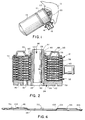
- FIG. 1 An exemplary embodiment of a heat exchanger made according to the invention is illustrated in Fig. 1 in the environment of an internal combustion engine having an engine block 10.
- a heat exchanger 12 connected to an oil filter 14 serves as an oil cooler for a first fluid such as a lubricating oil for the engine.
- the heat exchanger 12 includes inlet and outlet lines 16 and 18, respectively, for a second fluid which may be, e.g., an engine coolant or the like.
- lubricating oil is directed to the heat exchanger 12 via a passage 20 in the engine block 10 while return lubricating oil is received by the engine via a passage 22.
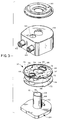
- the heat exchanger 12 includes a header plate 24 which is provided with a central opening 26 defined by a column 28 integrally formed with the header plate 24, and the header plate 24 also has a radial opening 30.
- a plurality of heat exchange units 32 are stacked on the header plate 24.
- the heat exchange units 32 each comprise a pair of plates 34 and 36 joined together at inner and outer peripheral edges 38 and 40 to thereby sealingly define a plurality of first chambers 42 for the flow of the lubricating oil wherein a column-receiving opening 44 is formed radially inwardly of the first chambers 42 thereof.
- the heat exchange units 32 further include aligned first openings 46 and aligned second openings 48 on opposite sides of the column-receiving openings 44 for joining the first chambers 42 in a first fluid flow path, and the radial opening 30 in the header plate 24 comprises a first fluid inlet for directing the lubricating oil through one of the first openings 46 into the first fluid flow path where it flows until it reaches a first fluid outlet 50 therefor.
- the heat exchange units 32 are stacked on the header plate 24 about the column 28 where they are arranged in a spaced series by spacer means in the form of buttons 52 which serve to define a plurality of second chambers 54 for the flow of the coolant between each pair of the spaced series of heat exchange units 32. With this arrangement, a tank 56 containing the first fluid outlet 50 covers the heat exchange units 32 stacked on the header plate 24 and, as best shown in Fig. 2, the tank 56 is integrally secured to the header plate 24 as at 58 and to the column 28 as at 60.
- the tank 56 is advantageously secured in a manner such as brazing so as to sealingly confine the coolant or cooling liquid within the tank 56 as it flows through the second chambers 54.
- the tank 56 has an inlet 62 for directing the coolant into the second chambers 54 and an outlet 64 for receiving the coolant from the second chambers 54.
- the coolant flows through the second chambers 54 in a second fluid flow path which is generally represented by the arrows 66, i.e., substantially entirely about the plates such as 34 and 36.
- the heat exchange units may be sealingly formed at the time of brazing the tank 56 to the header plate 24 and the column 28. This may all be done at one time by appropriately assembling all of the components before placing the heat exchanger in a brazing oven. As a result, the manufacture of the heat exchanger is greatly simplified which leads to still further cost savings.
- the header plate 24 and column 28 may be advantageously integrally formed by impact extruding aluminum.
- the heat exchange units 32 and the column 28 have cooperative alignment means, preferably in the form of a tab and recess arrangement wherein the column 28 includes a pair of integrally extruded axially extending tabs or ears 68 and 70 and the plates, such as 34, have a pair of corresponding tab-receiving recesses 72 and 74, respectively, which serve to ensure proper alignment when the heat exchange units are stacked on the header plates. More specifically, the tabs 68 and 70 and tab-receiving recesses 72 and 74 thereby serve to ensure alignment of the respective ones of the first and second openings 46 and 48.
- the plates such as 34 may have ears 73 and 75 formed on the outer peripheral edges thereof.
- the header plate 24 as well as the tank 56 may then be formed so as to have a non-circular cross-section so as to generally conform to the shape of the plates having the ears thereon. As a result, the alignment of all of these components for assembly is thereby facilitated to further reduce cost.
- buttons 52 are arranged in a common pattern on surfaces of the plates 34 and 36 facing away from the first chambers 42 of the heat exchange units 32. With this arrangement, the buttons 52 arrange the heat exchange units 32 in a spaced series. As a result, the buttons 52 define a plurality of second chambers 54 for the flow of the coolant between each pair of the spaced series of heat exchange units 32.
- the heat exchange units 32 have a separate turbulator 76 which is disposed within the first chambers 42 of each of the heat exchange units. It will be appreciated by referring to Figs. 5 and 6, however, that the heat exchange units 32 may each include an integrally formed turbulator. More specifically, the turbulator may be formed by a plurality of parallel indentations 78 in a ripple pattern on surfaces of the plates 34 and 36 facing toward the first chambers 42 thereof.
- the plates 34 and 36 making up any one of the heat exchange units 32 are identical in every respect which also serves to reduce the cost of manufacture and assembly rather significantly. It will be appreciated, however, that the plates, such as 34 and 36, of each one of the heat exchange units 32 are inverted relative to one another to thereby be disposed with the respective buttons 52 facing outwardly of the first chamber 42 thereof. Also, by forming the parallel indentations 78 at an angle to the axis 79 as shown in Fig. 5, the respective indentations 78 of the plates 34 and 36 making up any one of the heat exchange units 32 are at twice that angle to form the turbulator. Referring once again to Fig.
- the column 28 will be seen to be hollow to receive a suitable conduit or rigid tube 80 therewithin.
- the conduit or tube 80 has one end 82 adapted to be connected to the engine block 10 or a fitting therein, and it has an opposite end 87 to which the filter 14 (see Fig. 1) may be mounted.
- the conduit or tube 80 serves as a return path as indicated by the arrow 86 for lubricating oil which is leaving the filter 14.
- the radial opening 30 in the header plate 24 comprises a lubricating oil inlet and the radial opening 50 in the tank 56 comprises a lubricating oil outlet.
- a lubricating oil may thereby pass through the passage 20 in the engine block 10, and then through the heat exchanger 12 by means of the respective aligned first and second openings 46 and 48 in the heat exchange units 32.
- the lubricating oil will pass from the heat exchanger 12 through the lubricating oil outlet 50 into the space 88 between the tank 56 and the dome 90 which will have an outlet 92 through which the lubricating oil may be directed into the filter 14.
- first chambers 42 comprise lubricating oil chambers and the second chambers 54 comprise coolant, i.e., cooling liquid, chambers and the second inlet 16 and second outlet 18 comprise, respectively, a coolant or cooling liquid inlet and outlet.
- coolant i.e., cooling liquid
- the header plate 24 may either comprise a substantially flat surface 94 on the bottom thereof or, alternatively, (see Fig. 7) the header plate 24 may include a stand-off 96 which is advantageously integrally formed by impact extrusion with the header plate 24 on the side thereof opposite the column 28.
- the flat surface 94 or the stand-off 96 includes means for creating a seal against the engine block.
- the flat surface 94 and the stand-off 96 each include an O-ring receiving recess 97 and 98, respectively.
- the O-ring receiving recesses 97 and 98 are advantageously integrally formed during the impact extrusion process on the side of the header plate 24 opposite the column 28. In this manner, the header plate 24 may be sealed against the engine block 10 about the lubricating oil passage 20 provided therein.
- the stand-off 96 may be utilized where it is desired to isolate the heat exchanger 12 from the heat present in the engine block 10.
- the present invention accomplishes a number of important objectives among which are the fact that the total number of components has been significantly reduced to thereby facilitate assembly while reducing cost. This also serves to eliminate a number of potential leak joints.
- the present invention eliminates the need for assembly and brazing fixtures as well as the need for a separate turbulator while also making it possible to incorporate an integral stand-off for further enhancing heat transfer characteristics.
Applications Claiming Priority (2)
| Application Number | Priority Date | Filing Date | Title |
|---|---|---|---|
| US651548 | 1991-02-06 | ||
| US07/651,548 US5078209A (en) | 1991-02-06 | 1991-02-06 | Heat exchanger assembly |
Publications (2)
| Publication Number | Publication Date |
|---|---|
| EP0498108A1 true EP0498108A1 (de) | 1992-08-12 |
| EP0498108B1 EP0498108B1 (de) | 1995-07-12 |
Family
ID=24613268
Family Applications (1)
| Application Number | Title | Priority Date | Filing Date |
|---|---|---|---|
| EP91309889A Expired - Lifetime EP0498108B1 (de) | 1991-02-06 | 1991-10-25 | Wärmeaustauscher-Vorrichtung |
Country Status (11)
| Country | Link |
|---|---|
| US (1) | US5078209A (de) |
| EP (1) | EP0498108B1 (de) |
| JP (1) | JP3234252B2 (de) |
| KR (1) | KR100227880B1 (de) |
| AT (1) | ATE125034T1 (de) |
| AU (1) | AU632027B2 (de) |
| BR (1) | BR9102824A (de) |
| CA (1) | CA2044819C (de) |
| DE (1) | DE69111218T2 (de) |
| ES (1) | ES2077179T3 (de) |
| MX (1) | MX9100738A (de) |
Families Citing this family (49)
| Publication number | Priority date | Publication date | Assignee | Title |
|---|---|---|---|---|
| DE4128153C2 (de) * | 1991-08-24 | 1994-08-25 | Behr Gmbh & Co | Scheibenölkühler |
| EP0563951B1 (de) * | 1992-04-02 | 1999-02-17 | Denso Corporation | Wärmetauscher |
| JPH085279A (ja) * | 1994-06-20 | 1996-01-12 | Nippondenso Co Ltd | 熱交換器 |
| WO1998044305A1 (en) | 1997-04-02 | 1998-10-08 | Creare Inc. | Radial flow heat exchanger |
| FI109148B (fi) * | 1997-12-10 | 2002-05-31 | Vahterus Oy | Levylämmönvaihdin |
| DE19802012C2 (de) * | 1998-01-21 | 2002-05-23 | Modine Mfg Co | Gehäuseloser Plattenwärmetauscher |
| US6032503A (en) | 1998-11-23 | 2000-03-07 | Modine Manufacturing Company | Method and apparatus for roll forming a plurality of heat exchanger fin strips |
| US6446712B1 (en) * | 1999-02-23 | 2002-09-10 | Long Manufacturing Ltd. | Radial flow annular heat exchangers |
| CA2312113C (en) | 2000-06-23 | 2005-09-13 | Long Manufacturing Ltd. | Heat exchanger with parallel flowing fluids |
| US6997238B1 (en) | 2001-02-27 | 2006-02-14 | W.S. Darley & Co. | Cooler plate and gearbox assembly |
| US20020162646A1 (en) | 2001-03-13 | 2002-11-07 | Haasch James T. | Angled turbulator for use in heat exchangers |
| US7004237B2 (en) * | 2001-06-29 | 2006-02-28 | Delaware Capital Formation, Inc. | Shell and plate heat exchanger |
| DE10132120A1 (de) * | 2001-07-03 | 2003-01-16 | Deere & Co | Ölkühler |
| DE10207116B4 (de) * | 2002-02-20 | 2004-02-26 | P21 - Power For The 21St Century Gmbh | Wärmetauschersystem |
| CA2384712A1 (en) * | 2002-05-03 | 2003-11-03 | Michel St. Pierre | Heat exchanger with nest flange-formed passageway |
| US6953009B2 (en) * | 2002-05-14 | 2005-10-11 | Modine Manufacturing Company | Method and apparatus for vaporizing fuel for a reformer fuel cell system |
| GB0220652D0 (en) * | 2002-09-05 | 2002-10-16 | Chart Heat Exchangers Ltd | Heat exchanger |
| US20040099408A1 (en) * | 2002-11-26 | 2004-05-27 | Shabtay Yoram Leon | Interconnected microchannel tube |
| US7063047B2 (en) * | 2003-09-16 | 2006-06-20 | Modine Manufacturing Company | Fuel vaporizer for a reformer type fuel cell system |
| US6976531B2 (en) * | 2003-10-22 | 2005-12-20 | Dana Canada Corporation | Heat exchanger, method of forming a sleeve which may be used in the heat exchanger, and a sleeve formed by the method |
| CA2454283A1 (en) * | 2003-12-29 | 2005-06-29 | Anis Muhammad | Insert molded structure and method for the manufacture thereof |
| DE102004004975B4 (de) * | 2004-01-31 | 2015-04-23 | Modine Manufacturing Co. | Plattenwärmeübertrager |
| ITBO20040636A1 (it) * | 2004-10-15 | 2005-01-15 | Teclab S C R L | Recuperatore di calore per la condensazione dei fumi |
| US7178581B2 (en) | 2004-10-19 | 2007-02-20 | Dana Canada Corporation | Plate-type heat exchanger |
| US7540431B2 (en) * | 2004-11-24 | 2009-06-02 | Dana Canada Corporation | By-pass valve for heat exchanger |
| US7644732B2 (en) * | 2005-04-20 | 2010-01-12 | Dana Canada Corporation | Slide-in flapper valves |
| US7828014B2 (en) * | 2005-04-20 | 2010-11-09 | Dana Canada Corporation | Self-riveting flapper valves |
| US7306030B2 (en) * | 2005-04-20 | 2007-12-11 | Dana Canada Corporation | Snap-in baffle insert for fluid devices |
| US7222641B2 (en) * | 2005-04-20 | 2007-05-29 | Dana Canada Corporation | Snap-in flapper valve assembly |
| US20060237079A1 (en) * | 2005-04-20 | 2006-10-26 | Cheadle Brian E | Self-riveting flapper valves |
| US7735520B2 (en) * | 2005-04-20 | 2010-06-15 | Dana Canada Corporation | Tubular flapper valves |
| US20060237184A1 (en) * | 2005-04-20 | 2006-10-26 | Yuri Peric | Tubular flapper valves |
| US7318451B2 (en) * | 2005-04-20 | 2008-01-15 | Dana Canada Corporation | Flapper valves with spring tabs |
| JP2007147186A (ja) * | 2005-11-29 | 2007-06-14 | Calsonic Kansei Corp | ハウジングレス式オイルクーラのコア部構造。 |
| SE529808C2 (sv) * | 2006-04-06 | 2007-11-27 | Alfa Laval Corp Ab | Plattvärmeväxlare |
| US8453721B2 (en) * | 2007-01-31 | 2013-06-04 | Tranter, Inc. | Seals for a stacked-plate heat exchanger |
| EP2427716A4 (de) * | 2009-05-09 | 2014-06-18 | Tranter Inc | Wärmetauscher mit zugänglichem kern |
| KR20120041450A (ko) * | 2010-10-21 | 2012-05-02 | 삼성전자주식회사 | 냉장고용 워터 탱크를 구비한 냉장고 |
| US8911620B2 (en) * | 2010-11-29 | 2014-12-16 | Vesa S. Silegren | Universal spin-on oil filter adapter |
| US9664449B2 (en) * | 2011-08-05 | 2017-05-30 | Dana Canada Corporation | System with heat exchanger with side entry fitting |
| DE102013110355A1 (de) * | 2013-09-19 | 2015-03-19 | Osram Opto Semiconductors Gmbh | Optoelektronisches Halbleiterbauelement und Verfahren zum Herstellen eines Leiterrahmenverbunds |
| WO2016011550A1 (en) * | 2014-07-21 | 2016-01-28 | Dana Canada Corporation | Heat exchanger with flow obstructions to reduce fluid dead zones |
| DE102015010885A1 (de) * | 2015-08-20 | 2017-02-23 | Modine Manufacturing Company | Wärmetauscher und Herstellungsverfahren |
| IT201600115641A1 (it) * | 2016-11-16 | 2018-05-16 | Ufi Filters Spa | Un assieme di filtrazione e regolazione della temperatura olio motore |
| US10914533B2 (en) * | 2017-03-24 | 2021-02-09 | Hanon Systems | Intercooler for improved durability |
| US11453160B2 (en) | 2020-01-24 | 2022-09-27 | Hamilton Sundstrand Corporation | Method of building a heat exchanger |
| US11460252B2 (en) | 2020-01-24 | 2022-10-04 | Hamilton Sundstrand Corporation | Header arrangement for additively manufactured heat exchanger |
| US11441850B2 (en) * | 2020-01-24 | 2022-09-13 | Hamilton Sundstrand Corporation | Integral mounting arm for heat exchanger |
| US11703283B2 (en) | 2020-01-24 | 2023-07-18 | Hamilton Sundstrand Corporation | Radial configuration for heat exchanger core |
Citations (1)
| Publication number | Priority date | Publication date | Assignee | Title |
|---|---|---|---|---|
| GB2140908A (en) * | 1983-04-13 | 1984-12-05 | Nippon Denso Co | Heat exchanger |
Family Cites Families (19)
| Publication number | Priority date | Publication date | Assignee | Title |
|---|---|---|---|---|
| US1736906A (en) * | 1927-07-26 | 1929-11-26 | Flintermann Gerhard | Heat-exchange device |
| US2222721A (en) * | 1936-04-13 | 1940-11-26 | Gen Motors Corp | Oil cooler |
| US2360123A (en) * | 1942-09-18 | 1944-10-10 | Gen Motors Corp | Oil cooler |
| US2511084A (en) * | 1947-11-07 | 1950-06-13 | Young Radiator Co | Heat-exchanger core |
| US2702021A (en) * | 1948-09-11 | 1955-02-15 | Parker Pen Co | Fountain pen |
| DE1928146A1 (de) * | 1968-06-06 | 1969-12-11 | Delaney Gallay Ltd | Waermeaustauscher |
| DE2233737C2 (de) * | 1971-07-12 | 1983-02-03 | Société Anonyme Française du Ferodo, 75017 Paris | Wärmetauscher, insbesondere Kühler für ein Kraftfahrzeug |
| BE794794A (fr) * | 1971-11-04 | 1973-05-16 | Modine Mfg Cy | Appareil echangeur de chaleur |
| US4360055A (en) * | 1976-09-08 | 1982-11-23 | Modine Manufacturing Company | Heat exchanger |
| US4258785A (en) * | 1980-02-08 | 1981-03-31 | Borg-Warner Corporation | Heat exchanger interplate fitting |
| FR2494418A1 (fr) * | 1980-11-17 | 1982-05-21 | Chausson Usines Sa | Echangeur de chaleur pour fluides divers, liquides ou gazeux comportant des demi-lames assemblees delimitant un faisceau tubulaire |
| DE3222278C2 (de) * | 1982-06-14 | 1990-06-21 | Kühlerfabrik Längerer & Reich GmbH & Co KG, 7024 Filderstadt | Wasserkühler, insbesondere für eine Brennkraftmaschine |
| US4561494A (en) * | 1983-04-29 | 1985-12-31 | Modine Manufacturing Company | Heat exchanger with back to back turbulators and flow directing embossments |
| US4669532A (en) * | 1984-04-23 | 1987-06-02 | Kabushiki Kaisha Tsuchiya Seisakusho | Heat exchanger with temperature responsive bypass |
| JPS6144294A (ja) * | 1984-08-07 | 1986-03-03 | Nippon Denso Co Ltd | 熱交換器 |
| DE3440064A1 (de) * | 1984-11-02 | 1986-05-07 | Süddeutsche Kühlerfabrik Julius Fr. Behr GmbH & Co KG, 7000 Stuttgart | Oelkuehler |
| US4708199A (en) * | 1985-02-28 | 1987-11-24 | Kabushiki Kaisha Tsuchiya Seisakusho | Heat exchanger |
| JPH073315B2 (ja) * | 1985-06-25 | 1995-01-18 | 日本電装株式会社 | 熱交換器 |
| US4892136A (en) * | 1986-12-31 | 1990-01-09 | Kabushiki Kaisha Tsuchiya Seisakusho | Heat exchanger |
-
1991
- 1991-02-06 US US07/651,548 patent/US5078209A/en not_active Expired - Lifetime
- 1991-06-14 AU AU78419/91A patent/AU632027B2/en not_active Ceased
- 1991-06-17 CA CA002044819A patent/CA2044819C/en not_active Expired - Fee Related
- 1991-07-04 BR BR919102824A patent/BR9102824A/pt not_active IP Right Cessation
- 1991-08-09 JP JP22364191A patent/JP3234252B2/ja not_active Expired - Fee Related
- 1991-08-20 MX MX9100738A patent/MX9100738A/es not_active IP Right Cessation
- 1991-08-23 KR KR1019910014575A patent/KR100227880B1/ko not_active IP Right Cessation
- 1991-10-25 EP EP91309889A patent/EP0498108B1/de not_active Expired - Lifetime
- 1991-10-25 DE DE69111218T patent/DE69111218T2/de not_active Expired - Fee Related
- 1991-10-25 ES ES91309889T patent/ES2077179T3/es not_active Expired - Lifetime
- 1991-10-25 AT AT91309889T patent/ATE125034T1/de not_active IP Right Cessation
Patent Citations (1)
| Publication number | Priority date | Publication date | Assignee | Title |
|---|---|---|---|---|
| GB2140908A (en) * | 1983-04-13 | 1984-12-05 | Nippon Denso Co | Heat exchanger |
Non-Patent Citations (1)
| Title |
|---|
| PATENT ABSTRACTS OF JAPAN vol. 014, no. 042 (M-0925)25 January 1990 & JP-A-1 273 666 ( TOYO RADIATOR CO LTD ) 1 November 1989 * |
Also Published As
| Publication number | Publication date |
|---|---|
| KR920016806A (ko) | 1992-09-25 |
| JP3234252B2 (ja) | 2001-12-04 |
| CA2044819A1 (en) | 1992-08-07 |
| JPH04260790A (ja) | 1992-09-16 |
| ATE125034T1 (de) | 1995-07-15 |
| CA2044819C (en) | 2003-12-09 |
| AU7841991A (en) | 1992-08-20 |
| KR100227880B1 (ko) | 1999-11-01 |
| MX9100738A (es) | 1993-01-01 |
| DE69111218T2 (de) | 1996-02-29 |
| EP0498108B1 (de) | 1995-07-12 |
| DE69111218D1 (de) | 1995-08-17 |
| ES2077179T3 (es) | 1995-11-16 |
| BR9102824A (pt) | 1992-10-27 |
| AU632027B2 (en) | 1992-12-10 |
| US5078209A (en) | 1992-01-07 |
Similar Documents
| Publication | Publication Date | Title |
|---|---|---|
| EP0498108A1 (de) | Wärmeaustauscher-Vorrichtung | |
| US5810071A (en) | Heat exchanger | |
| JP3349524B2 (ja) | モジュール、熱交換器及びモジュール式熱交換器 | |
| US3265126A (en) | Heat exchanger | |
| EP0344206B1 (de) | Kombinierter filter und wärmeaustauscher | |
| US5343936A (en) | Spiral ripple circumferential flow heat exchanger | |
| US5526876A (en) | Heat exchanger | |
| US4561494A (en) | Heat exchanger with back to back turbulators and flow directing embossments | |
| US5146980A (en) | Plate type heat echanger, in particular for the cooling of lubricating oil in an automotive vehicle | |
| AU656464B2 (en) | High pressure, long life, aluminum heat exchanger construction | |
| JPH10206074A (ja) | 一体型熱交換器 | |
| US11274884B2 (en) | Heat exchanger module with an adapter module for direct mounting to a vehicle component | |
| US5409058A (en) | Heat exchanging apparatus | |
| JPH0623528B2 (ja) | 内燃機関用熱交換器 | |
| US6446712B1 (en) | Radial flow annular heat exchangers | |
| US5765632A (en) | Plate-type heat exchanger, in particular an oil cooler for a motor vehicle | |
| US5588485A (en) | Plate-type heat exchanger, for use especially as an oil cooler | |
| CA2257076C (en) | Radial flow annular heat exchangers | |
| JP2998422B2 (ja) | 熱交換器 | |
| JPH08219664A (ja) | 熱交換器 | |
| KR0129788Y1 (ko) | 열교환기 | |
| JPH10227591A (ja) | Egrガス冷却装置 | |
| JPH04356686A (ja) | オイルクーラ | |
| JPH05172476A (ja) | 熱交換器 | |
| JPH07310994A (ja) | 熱交換器 |
Legal Events
| Date | Code | Title | Description |
|---|---|---|---|
| PUAI | Public reference made under article 153(3) epc to a published international application that has entered the european phase |
Free format text: ORIGINAL CODE: 0009012 |
|
| AK | Designated contracting states |
Kind code of ref document: A1 Designated state(s): AT DE ES FR GB IT NL SE |
|
| 17P | Request for examination filed |
Effective date: 19930212 |
|
| 17Q | First examination report despatched |
Effective date: 19930629 |
|
| GRAA | (expected) grant |
Free format text: ORIGINAL CODE: 0009210 |
|
| AK | Designated contracting states |
Kind code of ref document: B1 Designated state(s): AT DE ES FR GB IT NL SE |
|
| REF | Corresponds to: |
Ref document number: 125034 Country of ref document: AT Date of ref document: 19950715 Kind code of ref document: T |
|
| ITF | It: translation for a ep patent filed |
Owner name: JACOBACCI & PERANI S.P.A. |
|
| REF | Corresponds to: |
Ref document number: 69111218 Country of ref document: DE Date of ref document: 19950817 |
|
| ET | Fr: translation filed | ||
| REG | Reference to a national code |
Ref country code: ES Ref legal event code: FG2A Ref document number: 2077179 Country of ref document: ES Kind code of ref document: T3 |
|
| PLBE | No opposition filed within time limit |
Free format text: ORIGINAL CODE: 0009261 |
|
| STAA | Information on the status of an ep patent application or granted ep patent |
Free format text: STATUS: NO OPPOSITION FILED WITHIN TIME LIMIT |
|
| 26N | No opposition filed | ||
| REG | Reference to a national code |
Ref country code: GB Ref legal event code: IF02 |
|
| PGFP | Annual fee paid to national office [announced via postgrant information from national office to epo] |
Ref country code: NL Payment date: 20040929 Year of fee payment: 14 |
|
| PGFP | Annual fee paid to national office [announced via postgrant information from national office to epo] |
Ref country code: AT Payment date: 20041004 Year of fee payment: 14 |
|
| PGFP | Annual fee paid to national office [announced via postgrant information from national office to epo] |
Ref country code: ES Payment date: 20041110 Year of fee payment: 14 |
|
| PGFP | Annual fee paid to national office [announced via postgrant information from national office to epo] |
Ref country code: GB Payment date: 20051019 Year of fee payment: 15 |
|
| PG25 | Lapsed in a contracting state [announced via postgrant information from national office to epo] |
Ref country code: AT Free format text: LAPSE BECAUSE OF NON-PAYMENT OF DUE FEES Effective date: 20051025 |
|
| PG25 | Lapsed in a contracting state [announced via postgrant information from national office to epo] |
Ref country code: ES Free format text: LAPSE BECAUSE OF NON-PAYMENT OF DUE FEES Effective date: 20051026 |
|
| PGFP | Annual fee paid to national office [announced via postgrant information from national office to epo] |
Ref country code: SE Payment date: 20051027 Year of fee payment: 15 |
|
| PG25 | Lapsed in a contracting state [announced via postgrant information from national office to epo] |
Ref country code: NL Free format text: LAPSE BECAUSE OF NON-PAYMENT OF DUE FEES Effective date: 20060501 |
|
| NLV4 | Nl: lapsed or anulled due to non-payment of the annual fee |
Effective date: 20060501 |
|
| PG25 | Lapsed in a contracting state [announced via postgrant information from national office to epo] |
Ref country code: SE Free format text: LAPSE BECAUSE OF NON-PAYMENT OF DUE FEES Effective date: 20061026 |
|
| PGFP | Annual fee paid to national office [announced via postgrant information from national office to epo] |
Ref country code: IT Payment date: 20061031 Year of fee payment: 16 |
|
| PGFP | Annual fee paid to national office [announced via postgrant information from national office to epo] |
Ref country code: DE Payment date: 20061130 Year of fee payment: 16 |
|
| REG | Reference to a national code |
Ref country code: ES Ref legal event code: FD2A Effective date: 20051026 |
|
| EUG | Se: european patent has lapsed | ||
| GBPC | Gb: european patent ceased through non-payment of renewal fee |
Effective date: 20061025 |
|
| PG25 | Lapsed in a contracting state [announced via postgrant information from national office to epo] |
Ref country code: GB Free format text: LAPSE BECAUSE OF NON-PAYMENT OF DUE FEES Effective date: 20061025 |
|
| PG25 | Lapsed in a contracting state [announced via postgrant information from national office to epo] |
Ref country code: DE Free format text: LAPSE BECAUSE OF NON-PAYMENT OF DUE FEES Effective date: 20080501 |
|
| REG | Reference to a national code |
Ref country code: FR Ref legal event code: ST Effective date: 20080630 |
|
| PGFP | Annual fee paid to national office [announced via postgrant information from national office to epo] |
Ref country code: FR Payment date: 20061017 Year of fee payment: 16 |
|
| PG25 | Lapsed in a contracting state [announced via postgrant information from national office to epo] |
Ref country code: FR Free format text: LAPSE BECAUSE OF NON-PAYMENT OF DUE FEES Effective date: 20071031 |
|
| PG25 | Lapsed in a contracting state [announced via postgrant information from national office to epo] |
Ref country code: IT Free format text: LAPSE BECAUSE OF NON-PAYMENT OF DUE FEES Effective date: 20071025 |