EP0493395B1 - Skischuh - Google Patents
Skischuh Download PDFInfo
- Publication number
- EP0493395B1 EP0493395B1 EP90912018A EP90912018A EP0493395B1 EP 0493395 B1 EP0493395 B1 EP 0493395B1 EP 90912018 A EP90912018 A EP 90912018A EP 90912018 A EP90912018 A EP 90912018A EP 0493395 B1 EP0493395 B1 EP 0493395B1
- Authority
- EP
- European Patent Office
- Prior art keywords
- elastic element
- plate
- shell
- ski boot
- heel body
- Prior art date
- Legal status (The legal status is an assumption and is not a legal conclusion. Google has not performed a legal analysis and makes no representation as to the accuracy of the status listed.)
- Expired - Lifetime
Links
Images

Classifications
-
- A—HUMAN NECESSITIES
- A43—FOOTWEAR
- A43B—CHARACTERISTIC FEATURES OF FOOTWEAR; PARTS OF FOOTWEAR
- A43B5/00—Footwear for sporting purposes
- A43B5/04—Ski or like boots
- A43B5/0415—Accessories
- A43B5/0417—Accessories for soles or associated with soles of ski boots; for ski bindings
-
- A—HUMAN NECESSITIES
- A43—FOOTWEAR
- A43B—CHARACTERISTIC FEATURES OF FOOTWEAR; PARTS OF FOOTWEAR
- A43B21/00—Heels; Top-pieces or top-lifts
- A43B21/24—Heels; Top-pieces or top-lifts characterised by the constructive form
- A43B21/26—Resilient heels
-
- A—HUMAN NECESSITIES
- A43—FOOTWEAR
- A43B—CHARACTERISTIC FEATURES OF FOOTWEAR; PARTS OF FOOTWEAR
- A43B5/00—Footwear for sporting purposes
- A43B5/04—Ski or like boots
- A43B5/0415—Accessories
- A43B5/0417—Accessories for soles or associated with soles of ski boots; for ski bindings
- A43B5/0421—Accessories for soles or associated with soles of ski boots; for ski bindings located underneath the sole
Definitions
- the invention relates to a ski boot with a damping device and a rigid shell according to the preamble of claim 1.
- an elastic element is provided between the underside of a rigid shell and a sole, made of essentially solid or bending-resistant material, which absorbs impacts and shocks that act on the skier's leg, especially in the heel area.
- a sole made of essentially solid or bending-resistant material, which absorbs impacts and shocks that act on the skier's leg, especially in the heel area.
- This load can lead to undesired wear and tear, which does not optimally guarantee the firmness of the ski boot required to trigger a safety ski binding.
- CH-PS 587 032 shows further known designs; however, the elastic devices or inserts there have the purpose of facilitating the rolling movement when walking.
- DE-OS 37 42 918 also shows in some of its versions elastic elements in the heel area, the elastic elements being located directly in or on the heel.
- the heel is formed in one piece with the sole or attached to the underside of the shell by a releasable connection. Since there is a rigid rib between the elastic elements, which transmits the forces directly from the heel to the shell and thus to the skier's foot, the damping effect to be applied in the vertical plane is also lost here. Only forces that occur when the ski boot is in a certain position, such as when edging, can therefore be damped.
- the object of the present invention is to remedy this and to ensure effective damping without restricting the acting direction of force while maintaining the necessary strength.
- the object is achieved by the characterizing features of claim 1.
- the measures according to the invention result in guide surfaces for the elastic element which do not impair the effectiveness of the damping device, so that it can absorb these impacts from all directions. Furthermore, these guide surfaces ensure the strength required to release a bond.
- the measures according to claim 2 result in divided profiles with an advantageous design, the same strength being achieved with less material with respect to the main direction of loading.
- the operation of the damping device is improved in that the contact surface between the elastic element and the detachable heel increases.
- this configuration leads to better anchoring of the two parts to one another.
- a uniform pressure distribution between the elastic element and the shoulder is achieved by the embodiment according to claim 6.
- Claim 7 ensures an unimpeded relative movement between the shell and the heel by the heads of the fastening screws.
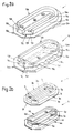
- FIG. 1 shows a ski boot according to the invention in side view
- FIG. 2 shows a diagram of the elastic element and the heel according to the first
- FIG. 2a according to the second and FIG. 2a according to the third exemplary embodiment
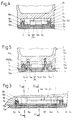
- 3 is a longitudinal section through a detail according to FIG. 1 according to the second exemplary embodiment
- FIGS. 4 and 5 are cross sections along the line IV-IV and V-V in FIG. 3.
- ski boot 1 shows a ski boot 1 in its entirety, with an elastic element 3 and a detachable heel 4 on its rigid shell 2.
- Figure 2 shows the elastic element 3 and the paragraph 4 together in an exploded view, each in an oblique view.
- the elastic element 3 has a plate 3a and an upwardly directed and self-contained profile 3b.
- the plate 3a has the shape of a trapezoid on its side facing the tip of the ski shoe, the area of the plate 3a facing away from the tip of the ski shoe is designed as a circular arc.
- the upward profile 3b has outer surfaces 3c which run inside and essentially parallel to the outer contour of the plate 3a.
- the profile 3b delimits a surface 3d with four through bores 5 which serve for the passage of fastening screws, not shown in this figure.
- the surface 3d and a top section 3e of the plate 3a running outside the profile 3b form a plane on which the elastic element 3 is supported horizontally on a bottom 2 a of the shell 2 of the ski boot 1 (not shown in this figure) (see FIG. 1). .
- the elastic element 3 On its underside 3f, the elastic element 3 has a recess 3g, which is designed as a groove and runs under or in the profile 3b (see FIGS. 3-5).
- FIG. 2 also shows the detachable shoulder 4 made of solid or bending-resistant material, said shoulder 4 having a plate 4a whose outer contour corresponds in plan view to that of plate 3a of the elastic element.
- the plate 4a has an upwardly projecting support part 4b, the side surfaces 4c of which are essentially the same inside and run parallel to the outer contour of the plate 4a, like the profile 3b of the elastic element 3.
- a surface 4d delimited by the supporting part 4b has four stepped bores 5a, which are used to hold fastening screws (not shown in this figure) (see FIG. 6 in FIG. 5 ) serve.
- FIGS. 2a to 5 show above all a basic embodiment of the invention. The interaction of the individual parts is now to be explained on the basis of a second embodiment according to FIGS. 2a to 5, which is preferred for practical use, from which figures the structure of the shell 2 of the ski boot 1 also emerges.
- FIG. 2a shows an elastic element 13 and a shoulder 14.
- the shape and structure of the two parts essentially correspond to the first embodiment according to FIG. 2, with the difference that the plate 13a of the elastic element 13 has two upwardly projecting profiles 13b, 13h with outer surfaces 13c, 13i and the plate 14a of the shoulder 14 two has protruding support parts 14b, 14h with outer surfaces 14c, 14i.
- the profiles 13b, 13h or the support parts 14b, 14h each delimit a surface 13d or 14d with through or stepped bores 15 or 15a.
- an intermediate plate 13j with a recess in which an intermediate plate 14j, which extends between the support parts 14b, 14h and the plate 14a, engages properly.
- Each of the intermediate plates 13j, 14j has an outer surface 13r, 14r, whose outer contour runs inside and essentially parallel to the outer contour of the respective plate 13a or 14a.
- the one profile 13b or the one support part 14b has a substantially U-shaped configuration in plan view, the open side of the profile 13b or the support part 14b pointing in the direction of the ski tip.
- the plate 13a of the elastic element 13 has, at a distance, a second profile 13h designed as a lying prism and the plate 14a of the shoulder 14 has a similarly designed and arranged support part 14h.
- the longitudinal axis of the second profile 13h or support part 14h is normal to the longitudinal axis of the ski boot.
- the elastic element 13 has on its underside 13f two recesses 13g, 13k, these being designed as grooves and running under or in the profiles 13b and 13h (see FIGS. 3-5).
- a top section 14m of the plate 14a which extends outside the support part 14b, has depressions 14n, which are also formed as lying segments of circular cylinders.
- Figures 3 to 5 show the paragraph 14 and the elastic element 13 positively connected to each other and mounted on the underside 2a of the shell 2.
- the positive connection is created by the downwardly projecting projections 13n elastic element 13, which engage in the recesses 14n of the shoulder 14, and by the engagement of the support parts 14b, 14h of the shoulder 14 in the recesses 13g, 13k on the underside 13f of the elastic element 13.
- the underside 2a of the shell 2 has a recess 2b with four downwardly projecting pins 7, each of which is provided for receiving a fastening screw 16.
- the profiles 13b, 13h of the elastic element 13 and the support parts 14b, 14h of the shoulder 14 also protrude into the recess 2b of the shell 2.
- the elastic element 13 is supported on the underside 2a of the shell 2 and on the end faces 7a of the pins 7.
- the outer surfaces 13c, 13i of the profiles 13b, 13h rest against side walls 2c of the recess 2b.
- the recess 2b corresponds in its front area to the profile of the side surfaces 13r of the intermediate plate 13j (not shown).
- the stepped bores 15a are formed on the underside of the shoulder 14 in such a way that the fastening screws 16 are countersunk with their heads 16a to an extent which, with any compression of the elastic element 13, causes the heads 16a to protrude from the underside of paragraph 14 avoided with certainty.
- the ski boot 1 is in the rest position. If, however, a blow or impact hits the ski boot 1 from below, the elastic element 3, 13 becomes between the underside 2a of the shell 2 or the End faces 7a of the pin 7 and the paragraph 4.14 compresses and causes damping.
- the elastic element 3, 13 is compressed between the side walls 2c of the recess 2b and the outer surfaces 14c, 14i of the support parts 14b, 14h of the shoulder 14.
- the heel plate can, for example, be provided with a longitudinal rib (s.14p in dash-dot lines in FIG. 2a) in order to increase the flexural strength of the heel.
- the height distance between the longitudinal rib and the underside of the shell is greater than the extent of the intended compression.
- the plate of the elastic element has a corresponding passage opening for the longitudinal rib, which does not influence the damping (see dash-dot line in FIG. 2a).
- other rib constructions with corresponding passage openings in the plate of the elastic element are also essential to the invention, for example in shape a cross or a double cross, a lying X-es and the like.
- FIG. 2b shows a variant in which the rib 4p of the surface 4d of the shoulder 4 is also assigned a rib 3p of the surface 3d of the elastic element 3.
- the structure and mode of operation of this variant correspond to those already described.
- the type of attachment of the heel to the underside of the ski boot is not restricted to the use of fastening screws, since riveting, gluing or welding is also conceivable.
Landscapes
- Health & Medical Sciences (AREA)
- General Health & Medical Sciences (AREA)
- Physical Education & Sports Medicine (AREA)
- Footwear And Its Accessory, Manufacturing Method And Apparatuses (AREA)
Priority Applications (1)
| Application Number | Priority Date | Filing Date | Title |
|---|---|---|---|
| AT90912018T ATE110939T1 (de) | 1990-07-23 | 1990-07-23 | Skischuh. |
Applications Claiming Priority (1)
| Application Number | Priority Date | Filing Date | Title |
|---|---|---|---|
| PCT/EP1990/001209 WO1992001397A1 (de) | 1990-07-23 | 1990-07-23 | Skischuh |
Publications (2)
| Publication Number | Publication Date |
|---|---|
| EP0493395A1 EP0493395A1 (de) | 1992-07-08 |
| EP0493395B1 true EP0493395B1 (de) | 1994-09-07 |
Family
ID=8165501
Family Applications (1)
| Application Number | Title | Priority Date | Filing Date |
|---|---|---|---|
| EP90912018A Expired - Lifetime EP0493395B1 (de) | 1990-07-23 | 1990-07-23 | Skischuh |
Country Status (5)
| Country | Link |
|---|---|
| US (1) | US5214865A (ja) |
| EP (1) | EP0493395B1 (ja) |
| JP (1) | JPH04506166A (ja) |
| DE (1) | DE59007082D1 (ja) |
| WO (1) | WO1992001397A1 (ja) |
Families Citing this family (19)
| Publication number | Priority date | Publication date | Assignee | Title |
|---|---|---|---|---|
| JPH0722082Y2 (ja) * | 1990-09-07 | 1995-05-24 | ダイワ精工株式会社 | スキー靴 |
| IT1259095B (it) * | 1992-05-06 | 1996-03-11 | Calzaturificio Tecnica Spa | Scarpone da sci biomeccanico |
| AT398705B (de) * | 1992-11-27 | 1995-01-25 | Wassermann Johann Dipl Ing Dr | Sicherheits-halteeinrichtung |
| AT401331B (de) * | 1992-12-17 | 1996-08-26 | Tyrolia Freizeitgeraete | Skischuh |
| AT401882B (de) * | 1993-06-01 | 1996-12-27 | Tyrolia Freizeitgeraete | Skischuh-skibindung-kombination |
| US5505477A (en) * | 1993-07-19 | 1996-04-09 | K-2 Corporation | Snowboard binding |
| US5474322A (en) * | 1994-07-21 | 1995-12-12 | Crush Snowboard Products, Inc. | Snowboard binding |
| FR2732197B1 (fr) * | 1995-03-28 | 1997-05-23 | Salomon Sa | Chaussure de ski avec moyens d'amortissement |
| AT1700U1 (de) * | 1996-10-25 | 1997-10-27 | Atomic Austria Gmbh | Skischuh |
| US6168173B1 (en) * | 1997-11-19 | 2001-01-02 | The Burton Corporation | Snowboard boot with binding interface |
| FR2774266B1 (fr) * | 1998-01-30 | 2000-03-10 | Salomon Sa | Chaussure de sport comportant une semelle adaptable a plusieurs normes |
| FR2810206B1 (fr) | 2000-06-19 | 2002-07-19 | Rossignol Sa | Chaussure pour la pratique du surf des neiges |
| CH694392A5 (fr) * | 2000-06-30 | 2004-12-31 | Lange Internat Sa | Chaussure de ski alpin. |
| ITTV20060213A1 (it) * | 2006-11-28 | 2008-05-29 | Tecnica Spa | Calzatura sportiva per sport di scivolamento |
| ITVE20070024U1 (it) * | 2007-07-05 | 2009-01-06 | Ober Alp Spa | Calzatura perfezionata per sci. |
| US8074380B2 (en) * | 2007-11-06 | 2011-12-13 | Black Diamond Equipment, Ltd. | Modular boot sole system |
| US9265300B2 (en) * | 2012-10-26 | 2016-02-23 | K-2 Corporation | Base for a ski boot and ski boot incorporating such a base |
| ITUD20130138A1 (it) * | 2013-10-25 | 2015-04-26 | Calzaturificio Dal Bello S R L | Calzatura sportiva per la pratica di sport invernali |
| KR20230060457A (ko) | 2021-10-27 | 2023-05-04 | 가부시키가이샤 레조낙·패키징 | 전지용 포장재 |
Family Cites Families (7)
| Publication number | Priority date | Publication date | Assignee | Title |
|---|---|---|---|---|
| DE1916935A1 (de) * | 1969-04-02 | 1970-10-15 | Rieker & Co | Skistiefel |
| ATA197874A (de) * | 1974-03-08 | 1977-09-15 | Smolka & Co Wiener Metall | Skischuh |
| IT1141823B (it) * | 1980-12-11 | 1986-10-08 | Dolomite Spa | Calzatura da sci con suola normalizzata |
| IT8420840V0 (it) * | 1984-02-13 | 1984-02-13 | Nordica Spa | Struttura di salvatacco particolarmente per scarponi da sci. |
| FR2610797B1 (fr) * | 1987-02-12 | 1989-05-12 | Salomon Sa | Chaussure de ski alpin a semelle munie d'un dispositif amortisseur |
| CH672976A5 (ja) * | 1987-09-18 | 1990-01-31 | Raichle Sportschuh Ag | |
| FR2620909B1 (fr) * | 1987-09-28 | 1989-12-01 | Salomon Sa | Semelle de chaussure de ski |
-
1990
- 1990-07-23 DE DE59007082T patent/DE59007082D1/de not_active Expired - Fee Related
- 1990-07-23 JP JP2511195A patent/JPH04506166A/ja active Granted
- 1990-07-23 WO PCT/EP1990/001209 patent/WO1992001397A1/de active IP Right Grant
- 1990-07-23 US US07/842,335 patent/US5214865A/en not_active Expired - Fee Related
- 1990-07-23 EP EP90912018A patent/EP0493395B1/de not_active Expired - Lifetime
Also Published As
| Publication number | Publication date |
|---|---|
| JPH04506166A (ja) | 1992-10-29 |
| JPH0579321B2 (ja) | 1993-11-02 |
| US5214865A (en) | 1993-06-01 |
| DE59007082D1 (de) | 1994-10-13 |
| WO1992001397A1 (de) | 1992-02-06 |
| EP0493395A1 (de) | 1992-07-08 |
Similar Documents
| Publication | Publication Date | Title |
|---|---|---|
| EP0493395B1 (de) | Skischuh | |
| AT404433B (de) | Dämpfungseinrichtung für stösse und schwingungen zwischen einem ski und einer bindung für einen schuh eines skiläufers | |
| EP0397969B1 (de) | Sicherheitsbindung für Snowboards | |
| EP0846021B1 (de) | Gleitgerät | |
| DE4101997C2 (de) | Verbindungseinrichtung zum Befestigen eines Schischuhes auf einem Schi | |
| DE4121114A1 (de) | Daempfungsvorrichtung fuer schuhe mit starrer schale | |
| DE4040383A1 (de) | Alpine sicherheitsskibindung | |
| DE3526298A1 (de) | Schuh, insbesondere sportschuh mit austauschbarem laufsohlenteil | |
| DE4402662A1 (de) | Ski sowie Bindungsplatte für einen Ski | |
| DE4033732B4 (de) | Verbindungseinrichtung für einen Schischuh auf einem Schi | |
| EP0129535A1 (de) | Einheit aus Langlaufbindung und Langlaufschuhen | |
| WO1998008405A1 (de) | Gedämpfter stollenschuh | |
| AT397474B (de) | Skilanglaufbindung | |
| DE2919639A1 (de) | Schuh mit auswechselbarem absatz | |
| EP0929350A1 (de) | Bindungsträgerplatte für einen ski | |
| DE3633101A1 (de) | Sicherheitsbindung fuer einen langlaufski | |
| AT357078B (de) | Skibindung mit einem zusatzgeraet zum tourengehen | |
| EP0221190B1 (de) | Skibindung | |
| DE102021101355A1 (de) | Gleitbrettbindung mit in horizontaler richtung veschraubtem gehäuse | |
| CH585530A5 (en) | Flexible ski boot with rocking hinge - has baseplate with rocking seat for uppers and shock absorbing springs | |
| AT500078B1 (de) | Sportschuh insbesondere schischuh | |
| DE19758190C2 (de) | Schuh für ein Gleitbrett | |
| AT367645B (de) | Sicherheitsskibindung | |
| DE3808878C2 (ja) | ||
| DE1428981C (de) | Sohlenplatte fur Skibindungen |
Legal Events
| Date | Code | Title | Description |
|---|---|---|---|
| PUAI | Public reference made under article 153(3) epc to a published international application that has entered the european phase |
Free format text: ORIGINAL CODE: 0009012 |
|
| 17P | Request for examination filed |
Effective date: 19920319 |
|
| AK | Designated contracting states |
Kind code of ref document: A1 Designated state(s): AT CH DE FR IT LI |
|
| RAP1 | Party data changed (applicant data changed or rights of an application transferred) |
Owner name: HTM SPORT S.P.A. |
|
| 17Q | First examination report despatched |
Effective date: 19931207 |
|
| GRAA | (expected) grant |
Free format text: ORIGINAL CODE: 0009210 |
|
| AK | Designated contracting states |
Kind code of ref document: B1 Designated state(s): AT CH DE FR IT LI |
|
| REF | Corresponds to: |
Ref document number: 110939 Country of ref document: AT Date of ref document: 19940915 Kind code of ref document: T |
|
| REF | Corresponds to: |
Ref document number: 59007082 Country of ref document: DE Date of ref document: 19941013 |
|
| ITF | It: translation for a ep patent filed |
Owner name: DR. ING. A. RACHELI & C. |
|
| ET | Fr: translation filed | ||
| PLBE | No opposition filed within time limit |
Free format text: ORIGINAL CODE: 0009261 |
|
| STAA | Information on the status of an ep patent application or granted ep patent |
Free format text: STATUS: NO OPPOSITION FILED WITHIN TIME LIMIT |
|
| PGFP | Annual fee paid to national office [announced via postgrant information from national office to epo] |
Ref country code: CH Payment date: 19950802 Year of fee payment: 6 |
|
| 26N | No opposition filed | ||
| PGFP | Annual fee paid to national office [announced via postgrant information from national office to epo] |
Ref country code: AT Payment date: 19960705 Year of fee payment: 7 |
|
| PGFP | Annual fee paid to national office [announced via postgrant information from national office to epo] |
Ref country code: DE Payment date: 19960713 Year of fee payment: 7 |
|
| PGFP | Annual fee paid to national office [announced via postgrant information from national office to epo] |
Ref country code: FR Payment date: 19960716 Year of fee payment: 7 |
|
| PG25 | Lapsed in a contracting state [announced via postgrant information from national office to epo] |
Ref country code: LI Effective date: 19960731 Ref country code: CH Effective date: 19960731 |
|
| REG | Reference to a national code |
Ref country code: CH Ref legal event code: PL |
|
| PG25 | Lapsed in a contracting state [announced via postgrant information from national office to epo] |
Ref country code: AT Free format text: LAPSE BECAUSE OF NON-PAYMENT OF DUE FEES Effective date: 19970723 |
|
| PG25 | Lapsed in a contracting state [announced via postgrant information from national office to epo] |
Ref country code: FR Free format text: LAPSE BECAUSE OF NON-PAYMENT OF DUE FEES Effective date: 19980331 |
|
| PG25 | Lapsed in a contracting state [announced via postgrant information from national office to epo] |
Ref country code: DE Free format text: LAPSE BECAUSE OF NON-PAYMENT OF DUE FEES Effective date: 19980401 |
|
| REG | Reference to a national code |
Ref country code: FR Ref legal event code: ST |
|
| PG25 | Lapsed in a contracting state [announced via postgrant information from national office to epo] |
Ref country code: IT Free format text: LAPSE BECAUSE OF NON-PAYMENT OF DUE FEES;WARNING: LAPSES OF ITALIAN PATENTS WITH EFFECTIVE DATE BEFORE 2007 MAY HAVE OCCURRED AT ANY TIME BEFORE 2007. THE CORRECT EFFECTIVE DATE MAY BE DIFFERENT FROM THE ONE RECORDED. Effective date: 20050723 |