EP0489985B1 - Vorrichtung zum Bedrucken von Marken - Google Patents
Vorrichtung zum Bedrucken von Marken Download PDFInfo
- Publication number
- EP0489985B1 EP0489985B1 EP90250307A EP90250307A EP0489985B1 EP 0489985 B1 EP0489985 B1 EP 0489985B1 EP 90250307 A EP90250307 A EP 90250307A EP 90250307 A EP90250307 A EP 90250307A EP 0489985 B1 EP0489985 B1 EP 0489985B1
- Authority
- EP
- European Patent Office
- Prior art keywords
- strip
- pawl
- printing
- drive
- roller
- Prior art date
- Legal status (The legal status is an assumption and is not a legal conclusion. Google has not performed a legal analysis and makes no representation as to the accuracy of the status listed.)
- Expired - Lifetime
Links
- 230000007246 mechanism Effects 0.000 claims description 5
- 238000004804 winding Methods 0.000 claims description 5
- 230000002093 peripheral effect Effects 0.000 claims description 2
- 238000000034 method Methods 0.000 description 5
- 230000008569 process Effects 0.000 description 5
- 230000002441 reversible effect Effects 0.000 description 2
- 230000009471 action Effects 0.000 description 1
- 230000004888 barrier function Effects 0.000 description 1
- 230000008901 benefit Effects 0.000 description 1
- 230000006835 compression Effects 0.000 description 1
- 238000007906 compression Methods 0.000 description 1
- 230000007423 decrease Effects 0.000 description 1
- 238000011161 development Methods 0.000 description 1
- 230000018109 developmental process Effects 0.000 description 1
- 238000011156 evaluation Methods 0.000 description 1
- 230000011664 signaling Effects 0.000 description 1
- 230000001960 triggered effect Effects 0.000 description 1
Images



Classifications
-
- B—PERFORMING OPERATIONS; TRANSPORTING
- B41—PRINTING; LINING MACHINES; TYPEWRITERS; STAMPS
- B41K—STAMPS; STAMPING OR NUMBERING APPARATUS OR DEVICES
- B41K3/00—Apparatus for stamping articles having integral means for supporting the articles to be stamped
- B41K3/44—Means for handling copy matter
- B41K3/48—Means for handling copy matter for conveying intermittently to or from stamping station
Definitions
- the invention relates to a device for printing marks according to the preamble of claim 1.
- a device for printing marks which is cut from a strip pulled off a roll.
- This device has a common drive for feeding the strip and for actuating a cutting device.
- the drive is provided with a pawl which is eccentrically mounted with respect to the drive axis and which engages with a roller which carries the strip for its gradual rotation, as well as with a cam-controlled lever which is connected to a movable knife of the cutting device.
- the reciprocating pawl is articulated on a pivotable lever which is actuated by a rotatably driven disc.
- This drive is therefore relatively complex and prone to failure. Nor can it be ruled out that when the strip is fed as quickly as possible there will be jerky movements that lead to sudden changes in tension in the strip. For this purpose, the risk of the strip tearing is very great, especially if it has transport holes.
- Devices for printing brands usually have printing units with adjustable type wheels. These type wheels are generally set by means of ratchet drives which gradually turn the type wheels until they have reached the desired position. However, this adjustment process is lengthy and requires an expensive adjustment mechanism.
- these printing units usually work with an ink ribbon reversibly driven between two spools.
- the design of the reversible drive and its switching when a tape end is reached are relatively complicated.
- a rotatably driven disc which performs a rotation of 180 ° during the feed, on which the pawl is attached eccentrically and which carries a cam for controlling the lever.
- the printing unit preferably has adjustable type wheels, which can expediently be rotated by a common shaft via friction clutches, and an independently controllable pawl is provided for each type wheel for locking the type wheel in a predetermined position.
- the printing unit is advantageously provided with an ink ribbon wound on two spool bodies, and it is expedient to provide a switch controlled by the winding state of the ink ribbon for determining the direction of rotation of the drive rotating the spool bodies.
- a gear wheel which is displaceably mounted in an elongated hole and is connected to the drive, can be provided which, depending on the direction of rotation of the drive, has one or the other the other of the two bobbins can be brought into engagement.
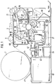
- the strip 2 is gradually withdrawn from a pre-printing roll 1 consisting of a wound paper strip; the advanced free end of the strip 2 is then printed and cut.
- the length of the cut mark corresponds to the respective advance of the strip.
- the stamp can be used as a stamp, ticket or other token.
- the strip 2 reaches guide rollers 3 and 4 to a pin roller 5, which is shown in more detail in FIG.
- the strip 2 contains transport holes 6 and the pin roller 5 has pins 7 emerging from its cylindrical peripheral surface, which engage in the transport holes 6.
- the pin roller 5 rotates, the strip 2 is therefore moved forward by a corresponding amount and pulled off the pre-pressure roller 1.
- Fig. 2 5 different strips 2 are shown on the right and left of the pin roller.
- the facing side shows how the pin roller 5 is designed when either the right or the left strip 2 is used.
- the pin roller 5 is rotatably arranged on bearings 8 on a fixed shaft 9.
- the shaft 9 is anchored in a wall 10.
- the pin roller 5 is pressed resiliently against a brake disk 15 lying against the wall 10 via a pressure disk 12, a compression spring 13 and a thrust washer 14.
- the pin roller 5 can thus only be rotated on the shaft 9 by overcoming an adjustable torque.
- the pin roller 5 carries on one end face at the same radial distance from the axis of rotation a plurality of pins 16 which are arranged at the same distance from one another and which can be brought into engagement with a pawl 17.
- the pawl 17 is eccentrically and rotatably attached to a disc 18 at one end; its other end lies freely on one of the pins 16.
- the disk 18 is rotated in the direction of the arrow by a motor 19.
- the disk 18 is in the position shown umd 180 ° rotated with respect to the initial position, in which the device an externally triggered Command to issue a printed mark expected.
- the pawl drive described has the advantage that the movement of the pin roller 5 does not start abruptly, but instead increases continuously in accordance with the course of a sinus curve until a maximum speed is reached and then decreases again steadily. Although an overall high transport speed for the strip 2 is achieved in this way, this movement is completely jerk-free, so that no such high tensile stresses in the strip 2 occur that there is a risk of tearing.
- the strip 2 passes between two guide plates 20 and 21 and two cutting blades 22 and 23 to the printing unit, which essentially consists of adjustable type wheels 24, a printing hammer 25 and an ink ribbon, not shown in FIG. 1.
- the print hammer 25 strikes against the type wheels 24, so that the intermediate front section of the strip 2 is printed with the aid of the ink ribbon. 1 thus shows the device in the printing position.
- the print hammer 25 is actuated by a pressure magnet 26 via an articulated pull rod 27.
- the rest position of the print hammer 25 is indicated in dashed lines.
- a motor 28 is used to set the individual type wheels 24, the output shaft of which is connected to a shaft 31 via gear wheels 29 and 30, and for each type wheel 24 there is a pawl magnet 32 with a pawl 33 which can be actuated by the latter.
- the adjusting mechanism is closer shown.
- the circumference of each type wheel 24 is provided with a number of notches corresponding to the number of printing types.
- the pawl 33 can snap into one of these notches, so that the type wheel 24 is locked in the printing position with the assigned printing type.
- the pawl 33 is pivotable about an axis 34 and is pulled by a spring 35 against the type wheel 24.
- the pawl 33 By energizing the pawl magnet 32, the pawl 33 can be disengaged from the type wheel 24 against the force of the spring 35 to be brought.
- Magnets 36 are fastened to each type wheel 24 in a predetermined arrangement, and each type wheel 24 is surrounded by a plurality of stationary Hall elements 37 which interact with the magnets 36.
- the instantaneous position of the type wheels 24 can be determined at any time from the output signals of the Hall elements 37.
- the shaft 31 contains a groove in which the inwardly directed pin of a plurality of clutch disks 38 mounted on the shaft 31 engages, so that these are connected to the shaft 31 in a rotationally fixed manner.
- the clutch discs 38 are pressed by plate springs 39 against the side surfaces of the type wheels 24, so that a frictional engagement occurs.
- the pawl magnets 32 are energized so that the pawls 33 release the associated type wheels 24, and the shaft 31 is rotated by the motor 28.
- the individual type wheels 24 are carried over the clutch discs 38.
- the Hall elements 37 detect the respective status of the type wheels 24, and when a type wheel has reached the intended pressure position, the associated pawl magnet 32 is de-energized so that the corresponding pawl 33 engages in the type wheel 24 and locks it.
- the further rotating clutch disks 38 then slide along the side surfaces of the locked type wheels 24. In this way, each type wheel 24 can be brought individually into the desired pressure position.
- the motor 28 is stopped again.
- the ink ribbon 40 (FIG. 4) used for printing is wound on two bobbins 41 and 42 and is passed between them through the printing unit. In operation, it is wound onto one bobbin and unwound from the other bobbin. After this has been completely unwound, the transport direction is reversed so that the empty bobbin is now used for winding and the other bobbin for unwinding.
- Fig. 4 shows the drive and switching device for the bobbin.
- a motor 43 which is reversible in the direction of rotation, drives a gearwheel 45 via its output shaft 44. This is in constant engagement with a gearwheel 47 mounted in an elongated hole 46. The position of the gear 47 is determined by the direction of rotation of the gear 45.
- the ink ribbon 40 is guided past two switching rollers 50 and 51, which are fixedly arranged on a switching lever 52 and 52a, respectively. This activates a switch 53, the switching state of which in turn determines the direction of rotation of the motor 43.
- the shift levers 52 and 52a are in their right position.
- the ink ribbon 40 presses against the shift roller 51 from the left, so that the shift lever 52a is held in this position.
- the diameter of the spool thus formed becomes so large that the ink ribbon 40 no longer touches the switching roller 51 and even runs past it at such a distance that the switching lever 52a for one Movement to its left position is released. This movement is effected by the ribbon 40 over the switching roller 50; however, only when the ribbon is completely unwound from the bobbin 42.
- the ends of the ribbon 40 are attached to the respective bobbin 41 and 42, so that when the tape is completely unwound, the ribbon movement is suddenly stopped and a relatively large tensile stress occurs in the ribbon, which is sufficient to flip the shift lever 52 and, via this, the shift lever 52a.
- the switch 53 is actuated and reverses the direction of rotation of the motor 43, ie the gear 47 detaches from the gear 49 and engages with the gear 48, so that now on the coils body 42 is wound and unwound from the bobbin 41. After the entire ribbon 40 has passed through the printing unit, the drive is then switched over again in the manner described above.
- the cutting device for separating the printed section from the strip 2 consists of the movable cutting knife 22 and the fixed cutting knife 23.
- the cutting knife 22 is connected via a rod 54 to a lever 56 which is pivotably mounted about an axis 55.
- a spring 57 pivots the lever 56 clockwise so that the cutting knife 22 is retracted over the rod 54 and clears the way for the strip 2.
- the disc 18 carries a pin-shaped cam 58 which, when the disc 18 rotates, abuts against the upper end of the lever 56 and pivots it counterclockwise, so that the cutting blade 22 is advanced via the rod 54 and, in cooperation with the cutting blade 23, the lower one Cut off section from strip 2.
- the cam 58 is arranged on the disk 18 such that the cutting knife 22 is put into action after the printing process and has returned to the starting position shown when the disk 18 has reached the rest position again.
- the cut-off marks fall onto a stacking plate 59 which is designed in such a way that the marks sliding down from it lie one above the other in an aligned manner.
- a light barrier 60 represents the end of the strip 2 firmly and triggers a suitable signaling device; in addition, the operational process is interrupted.
- the power supply unit and the control device for the overall device are located in a housing 61; individual control boards 62 assigned to the type wheels 24 contain the Hall elements 37 and the evaluation logic connected to them.
- the device shown is simple and compact.
- the individual functional units are modular and can be easily assembled and replaced on a motherboard.
Landscapes
- Cash Registers Or Receiving Machines (AREA)
- Inspection Of Paper Currency And Valuable Securities (AREA)
- Impression-Transfer Materials And Handling Thereof (AREA)
- Handling Of Sheets (AREA)
- Labeling Devices (AREA)
- Control Of Cutting Processes (AREA)
- Character Spaces And Line Spaces In Printers (AREA)
- Control Of Velocity Or Acceleration (AREA)
- Control Of Vending Devices And Auxiliary Devices For Vending Devices (AREA)
Priority Applications (6)
| Application Number | Priority Date | Filing Date | Title |
|---|---|---|---|
| DE59010264T DE59010264D1 (de) | 1990-12-10 | 1990-12-10 | Vorrichtung zum Bedrucken von Marken |
| DK90250307.7T DK0489985T3 (da) | 1990-12-10 | 1990-12-10 | Apparat til trykning af frimærker, billetter eller lignende artikler |
| AT90250307T ATE136259T1 (de) | 1990-12-10 | 1990-12-10 | Vorrichtung zum bedrucken von marken |
| EP90250307A EP0489985B1 (de) | 1990-12-10 | 1990-12-10 | Vorrichtung zum Bedrucken von Marken |
| ES90250307T ES2087123T3 (es) | 1990-12-10 | 1990-12-10 | Dispositivo para la impresion de sellos, billetes o articulos similares. |
| GR960401791T GR3020418T3 (en) | 1990-12-10 | 1996-07-02 | Device for printing stamps, tickets or similar articles |
Applications Claiming Priority (1)
| Application Number | Priority Date | Filing Date | Title |
|---|---|---|---|
| EP90250307A EP0489985B1 (de) | 1990-12-10 | 1990-12-10 | Vorrichtung zum Bedrucken von Marken |
Publications (2)
| Publication Number | Publication Date |
|---|---|
| EP0489985A1 EP0489985A1 (de) | 1992-06-17 |
| EP0489985B1 true EP0489985B1 (de) | 1996-04-03 |
Family
ID=8205239
Family Applications (1)
| Application Number | Title | Priority Date | Filing Date |
|---|---|---|---|
| EP90250307A Expired - Lifetime EP0489985B1 (de) | 1990-12-10 | 1990-12-10 | Vorrichtung zum Bedrucken von Marken |
Country Status (6)
| Country | Link |
|---|---|
| EP (1) | EP0489985B1 (da) |
| AT (1) | ATE136259T1 (da) |
| DE (1) | DE59010264D1 (da) |
| DK (1) | DK0489985T3 (da) |
| ES (1) | ES2087123T3 (da) |
| GR (1) | GR3020418T3 (da) |
Family Cites Families (7)
| Publication number | Priority date | Publication date | Assignee | Title |
|---|---|---|---|---|
| FR348109A (fr) * | 1904-11-11 | 1905-04-03 | Charles Edwin Beringer | Distributeur automatique de numéros |
| US2176690A (en) * | 1937-09-07 | 1939-10-17 | Rudie Julius | Feeding, printing, and cutting machine |
| FR849600A (fr) * | 1939-01-28 | 1939-11-27 | Machine à imprimer et à découper les étiquettes | |
| US2335718A (en) * | 1942-03-19 | 1943-11-30 | Pitney Bowes Postage Meter Co | Value stamping and vending machine |
| US3001122A (en) * | 1956-03-13 | 1961-09-19 | Philips Corp | Frequency transformation device |
| US2973707A (en) * | 1958-12-10 | 1961-03-07 | Henry A Crivelli | Ticket printing and issuing machine |
| NL6806264A (da) * | 1968-05-03 | 1969-11-05 |
-
1990
- 1990-12-10 ES ES90250307T patent/ES2087123T3/es not_active Expired - Lifetime
- 1990-12-10 DE DE59010264T patent/DE59010264D1/de not_active Expired - Fee Related
- 1990-12-10 AT AT90250307T patent/ATE136259T1/de not_active IP Right Cessation
- 1990-12-10 EP EP90250307A patent/EP0489985B1/de not_active Expired - Lifetime
- 1990-12-10 DK DK90250307.7T patent/DK0489985T3/da active
-
1996
- 1996-07-02 GR GR960401791T patent/GR3020418T3/el unknown
Also Published As
| Publication number | Publication date |
|---|---|
| DE59010264D1 (de) | 1996-05-09 |
| DK0489985T3 (da) | 1996-08-05 |
| ATE136259T1 (de) | 1996-04-15 |
| EP0489985A1 (de) | 1992-06-17 |
| GR3020418T3 (en) | 1996-10-31 |
| ES2087123T3 (es) | 1996-07-16 |
Similar Documents
| Publication | Publication Date | Title |
|---|---|---|
| DE1059930B (de) | Tastengesteuertes Druckwerk fuer Schreibmaschinen mit dreh- und verschiebbarem Typenzylinder | |
| DE2331080C3 (de) | Löschband-Transportvorrichtung | |
| DE3538048C2 (da) | ||
| DE3140642A1 (de) | Transportvorrichtung fuer blattfoermige aufzeichnungstraeger | |
| DE3447508A1 (de) | Getriebe | |
| DE1287591B (de) | Papiereinzieh- und Anzeigevorrichtung fuer kraftangetriebene Schreib- und aehnliche Maschinen | |
| EP0489985B1 (de) | Vorrichtung zum Bedrucken von Marken | |
| DE2166745A1 (de) | Shnelldrucker | |
| EP0566697B1 (de) | Transportvorrichtung für abschnitte eines aufzeichnungsträgers aus einem schreibwerk | |
| DE10155133A1 (de) | Vorrichtung zum Positionieren von entlang einer Führung verschiebbaren Elementen | |
| DE2549116C3 (de) | Druckeinrichtung mit einem vom Aufzeichnungsträger abschwenkbaren Druckkopf | |
| DE2242663B2 (de) | Einrichtung zum Transport eines Typenträgerwagens an Schreib- u.a. Büromaschinen | |
| DE3138008C2 (de) | Druckwerk für eine Handnummeriermaschine | |
| DE1229551B (de) | Vorrichtung zum Bedrucken von Aufzeichnungs-traegern | |
| DE1436676A1 (de) | Vorrichtung zur Unterdrueckung einer Rueckprallbewegung im Antriebswerk einer kraftgetriebenen Bueromaschine,insbesondere Schreibmaschine | |
| DE2549004B2 (de) | Vorrichtung zum Einstellen der Typenräder eines rotierenden Druckzylinders | |
| DE2135288A1 (de) | Einrichtung zum wahlweisen Einstellen von bewegbaren Gliedern | |
| EP1093894A2 (de) | Schneidvorrichtung | |
| DE2433952C3 (de) | Bandumwicklungsvorrichtung | |
| DE2733286C2 (de) | Vorrichtung zum Vorschub einer Farbfolie in einer Druck- bzw. Prägemaschine | |
| DE20115718U1 (de) | Vorrichtung zum beidseitigen Bedrucken von Bandware wie Kabel, Schläuche, Litzen etc. mittels Heißprägeverfahren | |
| DE1785410B2 (de) | Vorrichtung zum Anhalten der Antriebszylinder von Aufnahmespulen in einer Maschine zum Zwirnen von Textilfaden | |
| DE2916903C3 (de) | Druckwert für z.B. Büromaschinen | |
| AT119612B (de) | Schreibkasse. | |
| DE4315510C2 (de) | Drucker zum zeilenweisen Bedrucken mindestens eines Druckträgers |
Legal Events
| Date | Code | Title | Description |
|---|---|---|---|
| PUAI | Public reference made under article 153(3) epc to a published international application that has entered the european phase |
Free format text: ORIGINAL CODE: 0009012 |
|
| 17P | Request for examination filed |
Effective date: 19901219 |
|
| AK | Designated contracting states |
Kind code of ref document: A1 Designated state(s): AT BE CH DE DK ES FR GB GR IT LI LU NL SE |
|
| 17Q | First examination report despatched |
Effective date: 19940506 |
|
| GRAA | (expected) grant |
Free format text: ORIGINAL CODE: 0009210 |
|
| AK | Designated contracting states |
Kind code of ref document: B1 Designated state(s): AT BE CH DE DK ES FR GB GR IT LI LU NL SE |
|
| PG25 | Lapsed in a contracting state [announced via postgrant information from national office to epo] |
Ref country code: IT Free format text: LAPSE BECAUSE OF FAILURE TO SUBMIT A TRANSLATION OF THE DESCRIPTION OR TO PAY THE FEE WITHIN THE PRE;WARNING: LAPSES OF ITALIAN PATENTS WITH EFFECTIVE DATE BEFORE 2007 MAY HAVE OCCURRED AT ANY TIME BEFORE 2007. THE CORRECT EFFECTIVE DATE MAY BE DIFFERENT FROM THE ONE RECORDED.SCRIBED TIME-LIMIT Effective date: 19960403 Ref country code: FR Effective date: 19960403 Ref country code: GB Effective date: 19960403 |
|
| REF | Corresponds to: |
Ref document number: 136259 Country of ref document: AT Date of ref document: 19960415 Kind code of ref document: T |
|
| REF | Corresponds to: |
Ref document number: 59010264 Country of ref document: DE Date of ref document: 19960509 |
|
| REG | Reference to a national code |
Ref country code: CH Ref legal event code: NV Representative=s name: TROESCH SCHEIDEGGER WERNER AG |
|
| REG | Reference to a national code |
Ref country code: ES Ref legal event code: BA2A Ref document number: 2087123 Country of ref document: ES Kind code of ref document: T3 |
|
| REG | Reference to a national code |
Ref country code: ES Ref legal event code: FG2A Ref document number: 2087123 Country of ref document: ES Kind code of ref document: T3 |
|
| REG | Reference to a national code |
Ref country code: DK Ref legal event code: T3 |
|
| EN | Fr: translation not filed | ||
| REG | Reference to a national code |
Ref country code: GR Ref legal event code: FG4A Free format text: 3020418 |
|
| GBV | Gb: ep patent (uk) treated as always having been void in accordance with gb section 77(7)/1977 [no translation filed] |
Effective date: 19960403 |
|
| PG25 | Lapsed in a contracting state [announced via postgrant information from national office to epo] |
Ref country code: AT Effective date: 19961210 |
|
| PG25 | Lapsed in a contracting state [announced via postgrant information from national office to epo] |
Ref country code: LU Free format text: LAPSE BECAUSE OF NON-PAYMENT OF DUE FEES Effective date: 19961231 |
|
| PLBE | No opposition filed within time limit |
Free format text: ORIGINAL CODE: 0009261 |
|
| STAA | Information on the status of an ep patent application or granted ep patent |
Free format text: STATUS: NO OPPOSITION FILED WITHIN TIME LIMIT |
|
| 26N | No opposition filed | ||
| PGFP | Annual fee paid to national office [announced via postgrant information from national office to epo] |
Ref country code: DK Payment date: 19971216 Year of fee payment: 8 |
|
| PGFP | Annual fee paid to national office [announced via postgrant information from national office to epo] |
Ref country code: ES Payment date: 19971219 Year of fee payment: 8 |
|
| PGFP | Annual fee paid to national office [announced via postgrant information from national office to epo] |
Ref country code: SE Payment date: 19971223 Year of fee payment: 8 |
|
| PGFP | Annual fee paid to national office [announced via postgrant information from national office to epo] |
Ref country code: GR Payment date: 19971229 Year of fee payment: 8 |
|
| PGFP | Annual fee paid to national office [announced via postgrant information from national office to epo] |
Ref country code: BE Payment date: 19971231 Year of fee payment: 8 Ref country code: NL Payment date: 19971231 Year of fee payment: 8 |
|
| PGFP | Annual fee paid to national office [announced via postgrant information from national office to epo] |
Ref country code: DE Payment date: 19980108 Year of fee payment: 8 |
|
| PGFP | Annual fee paid to national office [announced via postgrant information from national office to epo] |
Ref country code: CH Payment date: 19980305 Year of fee payment: 8 |
|
| REG | Reference to a national code |
Ref country code: CH Ref legal event code: PUE Owner name: KLUESSENDORF AKTIENGESELLSCHAFT TRANSFER- KLUESSEN |
|
| PG25 | Lapsed in a contracting state [announced via postgrant information from national office to epo] |
Ref country code: DK Free format text: LAPSE BECAUSE OF NON-PAYMENT OF DUE FEES Effective date: 19981210 |
|
| PG25 | Lapsed in a contracting state [announced via postgrant information from national office to epo] |
Ref country code: SE Free format text: LAPSE BECAUSE OF NON-PAYMENT OF DUE FEES Effective date: 19981211 |
|
| PG25 | Lapsed in a contracting state [announced via postgrant information from national office to epo] |
Ref country code: GR Free format text: LAPSE BECAUSE OF NON-PAYMENT OF DUE FEES Effective date: 19981231 Ref country code: CH Free format text: LAPSE BECAUSE OF NON-PAYMENT OF DUE FEES Effective date: 19981231 Ref country code: BE Free format text: LAPSE BECAUSE OF NON-PAYMENT OF DUE FEES Effective date: 19981231 Ref country code: LI Free format text: LAPSE BECAUSE OF NON-PAYMENT OF DUE FEES Effective date: 19981231 |
|
| REG | Reference to a national code |
Ref country code: ES Ref legal event code: PC2A |
|
| BERE | Be: lapsed |
Owner name: KLUSSENDORF PRODUCKT UND VERTRIEBS G.M.B.H. Effective date: 19981231 |
|
| NLS | Nl: assignments of ep-patents |
Owner name: KLUESSENDORF PRODUKT UND VERTRIEBS GMBH |
|
| PG25 | Lapsed in a contracting state [announced via postgrant information from national office to epo] |
Ref country code: NL Free format text: LAPSE BECAUSE OF NON-PAYMENT OF DUE FEES Effective date: 19990701 |
|
| REG | Reference to a national code |
Ref country code: CH Ref legal event code: PL |
|
| NLV4 | Nl: lapsed or anulled due to non-payment of the annual fee |
Effective date: 19990701 |
|
| PG25 | Lapsed in a contracting state [announced via postgrant information from national office to epo] |
Ref country code: DE Free format text: LAPSE BECAUSE OF NON-PAYMENT OF DUE FEES Effective date: 19991001 |
|
| PG25 | Lapsed in a contracting state [announced via postgrant information from national office to epo] |
Ref country code: ES Free format text: LAPSE BECAUSE OF NON-PAYMENT OF DUE FEES Effective date: 19991211 |
|
| REG | Reference to a national code |
Ref country code: DK Ref legal event code: EBP |
|
| REG | Reference to a national code |
Ref country code: ES Ref legal event code: FD2A Effective date: 20000114 |