EP0488256B1 - Vorrichtung zum Auswählen von Sämlingen und zum Überführen derselben - Google Patents
Vorrichtung zum Auswählen von Sämlingen und zum Überführen derselben Download PDFInfo
- Publication number
- EP0488256B1 EP0488256B1 EP91120329A EP91120329A EP0488256B1 EP 0488256 B1 EP0488256 B1 EP 0488256B1 EP 91120329 A EP91120329 A EP 91120329A EP 91120329 A EP91120329 A EP 91120329A EP 0488256 B1 EP0488256 B1 EP 0488256B1
- Authority
- EP
- European Patent Office
- Prior art keywords
- seedlings
- transferring
- row
- selecting
- rearing
- Prior art date
- Legal status (The legal status is an assumption and is not a legal conclusion. Google has not performed a legal analysis and makes no representation as to the accuracy of the status listed.)
- Expired - Lifetime
Links
- 230000000384 rearing effect Effects 0.000 claims description 41
- 239000007787 solid Substances 0.000 description 9
- 230000006835 compression Effects 0.000 description 3
- 238000007906 compression Methods 0.000 description 3
- 229920003002 synthetic resin Polymers 0.000 description 2
- 239000000057 synthetic resin Substances 0.000 description 2
- 235000013339 cereals Nutrition 0.000 description 1
- 230000001419 dependent effect Effects 0.000 description 1
- 235000013399 edible fruits Nutrition 0.000 description 1
- 239000000463 material Substances 0.000 description 1
- 238000000034 method Methods 0.000 description 1
- 238000012986 modification Methods 0.000 description 1
- 230000004048 modification Effects 0.000 description 1
- 235000013311 vegetables Nutrition 0.000 description 1
Images







Classifications
-
- A—HUMAN NECESSITIES
- A01—AGRICULTURE; FORESTRY; ANIMAL HUSBANDRY; HUNTING; TRAPPING; FISHING
- A01G—HORTICULTURE; CULTIVATION OF VEGETABLES, FLOWERS, RICE, FRUIT, VINES, HOPS OR SEAWEED; FORESTRY; WATERING
- A01G9/00—Cultivation in receptacles, forcing-frames or greenhouses; Edging for beds, lawn or the like
- A01G9/02—Receptacles, e.g. flower-pots or boxes; Glasses for cultivating flowers
- A01G9/029—Receptacles for seedlings
- A01G9/0299—Handling or transporting of soil blocks or seedlings
-
- Y—GENERAL TAGGING OF NEW TECHNOLOGICAL DEVELOPMENTS; GENERAL TAGGING OF CROSS-SECTIONAL TECHNOLOGIES SPANNING OVER SEVERAL SECTIONS OF THE IPC; TECHNICAL SUBJECTS COVERED BY FORMER USPC CROSS-REFERENCE ART COLLECTIONS [XRACs] AND DIGESTS
- Y10—TECHNICAL SUBJECTS COVERED BY FORMER USPC
- Y10S—TECHNICAL SUBJECTS COVERED BY FORMER USPC CROSS-REFERENCE ART COLLECTIONS [XRACs] AND DIGESTS
- Y10S47/00—Plant husbandry
- Y10S47/901—Plant container with flats, filling, planting, or conveying
Definitions
- the present invention relates to an apparatus for selecting seedlings and transferring the same, and more particularly to an apparatus which can automatically take out seedlings cultured in rearing chambers of a culture tray and judge the quality of seedlings, and which can automatically transfer only good seedlings to a delivery tray.
- the culture tray has a number of rearing chambers which are arrayed in the form of lattice, and a seedling is reared in the respective rearing chamber.
- the seedlings are taken out of the culture tray by man power and examined with the naked eye to see whether they are good or bad in quality, and only good seedlings are picked up and transferred onto a delivery tray for delivering to the farmers.
- EP-A-0 426 549 discloses an apparatus , wherein a seedling is pushed out of its rearing chamber by means of a pusher.
- the pusher has two positions, a rest position and a fully extended end position.
- Detector means detect whether the seedling has sufficiently grown and judges the seedling for "good” or "bad". In this simple arrangement, the seedling is only examined in one position which is at the same time the end position in which the seedling is handled further.
- the culture tray having a plurality of rows of rearing chambers to rear seedlings is intermittently fed to a certain position by the first feeding device, the seedlings are examined by the sensor means whether they are good or bad in quality. Next, only good seedlings which are judged to be good by the sensor means are pushed out of the culture tray by actuation of the pusher of the pushing device. Thereafter, the good seedlings pushed upwardly are taken out of the rearing chambers and supplied to the transferring device. In the transferring device, the good seedlings are received and transferred to the delivery tray.
- the culture tray 1 is formed of synthetic resin sheet or the like and has a number of box-like receptacles, each receptacle defining therein rearing chamber 4, which are arrayed in the form of lattice.
- the box-like receptacle defining therein the rearing chamber 4 has a hole 5 at the bottom thereof.
- the rearing chamber 4 is filled with solid medium 6.
- a number of seedlings 2 are reared in all rearing chambers 4 of the culture tray 1. After the seedling 2 grows up to be a certain size, the seedling 2 is taken out of the rearing chamber 4 and transferred to the delivery tray 3.
- the delivery tray 3 is also formed of synthetic resin sheet or the like and is corrugated.
- the delivery tray 3 has a plurality of grooves 7 which receive a row of the seedlings 2 together with solid mediums 6 taken out of the culture tray 1.
- the apparatus for selecting seedlings and transferring the same comprises a base plate 8R extending horizontally and located on the right side, a base plate 8L having a lower horizontal plane than that of the base plate 8R and located on the left side, and a frame 9 supporting the base plate 8R and the base plate 8L.
- the culture tray 1 is placed above the base plate 8R, and the delivery tray 3 is placed above the base plate 8L.
- a culture tray feeding device 10 see Fig.
- a taking-out device 15 having a row of grippers 14 in which the good seedlings 2a pushed upwardly by the pushers 13 are taken out of the rearing chambers 4 and conveyed in the direction of the row of the rearing chambers 4, and a transferring device 17 having a transferring member 16 in which a row of the good seedlings 2a are received from the grippers 14 and transferred to the delivery tray 3.
- the transferring device 17 the row of the good seedlings 2a which has been already received by the transferring member 16 is pushed and transferred onto the delivery tray 3 when the next row of the good seedlings 2a is conveyed by the grippers 14.
- a delivery tray feeding device 18 for intermittently feeding the delivery tray 3 in the direction parallel to the feeding direction of the culture tray 1.
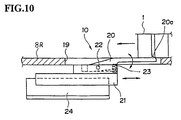
- the culture tray feeding device 10 is provided on the base plate 8R so as to place the culture tray 1 thereon as shown in Fig. 10. That is, the base plate 8R is formed with an oblong hole 19 extending in a feeding direction of the culture tray 1, and an engaging member 20 is loosely fitted with the oblong hole 19.
- the engaging member 20 is supported through a horizontal pin 22 by a slider 21 which is reciprocally movable under the base plate 8R along the feeding direction of the culture tray 1.
- the engaging member 20 is rotatably supported by the slider 21 so that a engaging portion 20a takes two positions where the engaging portion 20a projects from the oblong hole 19 to engage with the bottom of the culture tray 1 and where the engaging portion 20a retreats into the oblong hole 19 to disengage from the culture tray 1.
- the engaging member 20 is urged by a compression spring 23 so as to take a position of engaging with the bottom of the culture tray 1 in a normal condition.
- the slider 21 is reciprocally movable by a width of the rearing chamber 4 along a guide rail 24 installed under the base plate 8R.
- the culture tray 1 is moved to the left side by one pitch of the row of the rearing chamber 4 due to engagement of the engaging portion 20a and the culture tray 1.
- the engaging portion 20a is pushed by the bottom surface of the culture tray 1 and rotated slightly downwardly.
- the engaging portion 20a is engaged with the bottom of the next row of the rearing chamber 4.
- the culture tray 1 is intermittently fed by one pitch of the row of the rearing chamber 4.
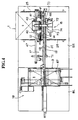
- guide plates 25 are provided in parallel with each other on the base plate 8R as shown in Figs. 4 and 5.
- a row of sensors 11 is disposed above the feeding passage of the culture tray 1 to examine whether the seedlings 2 are good or bad in quality as shown in Figs. 6, 7 and 9.
- the sensor 11 is reflecting type, and a row of sensors 11 are provided so as to correspond to the row of the rearing chambers 4.
- Reference numeral 26 denotes a supporting arm for supporting the sensor 11, each supporting arm 26 is fixedly secured to a lateral bar 27 extending in a direction of a row of the rearing chambers 4.
- Below the base plate 8R there are provided two air cylinders 28 and 29 connected to each other in series at both side ends of the lateral bar 27.
- the air cylinder 28 includes a cylinder rod 28a having an upper end which is connected to the lateral bar 27.
- the air cylinder 29 includes a cylinder rod 29a having a lower end which is connected to the frame 9.
- the sensor 11 is stopped at the three positions where the air cylinder rods 28a and 29a retreat, where the air cylinder rod 28a projects and the air cylinder rod 29 retreats, and where the air cylinder rods 28 and 29 project. Therefore, the growth degree of the seedling 2 is examined at the three positions in a vertical direction of the seedling 2. In this embodiment, only the seedling 2 which is judged to be good in all three positions is judged to be good quality.
- the culture tray 1 After judging a row of the seedlings 2 in quality, the culture tray 1 is fed by one pitch of the culture tray 1 by the culture tray feeding device 10.
- the pushing device 13 is provided with a row of pushers 12 so as correspond to the row of the sensors.
- the pusher 12 is provided perpendicularly to the base plate 8R as shown in Fig. 8.
- a row of holes 30 are provided on the base plate 8R to allow a row of pushers 12 to pass therethrough.
- Each pusher 12 is connected to a cylinder rod 33a of an air cylinder 33.
- the air cylinder 33 is connected to a clutch device 31 through a coupler 32.
- the air cylinders 33 corresponding to the seedlings 2 which are judged to be good by the sensors 11 are adapted to be actuated, whereby each pusher 12 actuated by the air cylinder 33 passes through the hole 5 formed on the bottom of the rearing chamber 4 and pushes only good seedling 2a.
- the pushing height is about two thirds of the depth of the rearing chamber 4, therefore, the lower portion of the solid medium 6 remains in the rearing chamber 4 at the first stage of pushing.
- the pusher 12 is formed with a truncated-cone-shaped cam 34 at the intermediate portion thereof, whereby the pusher 12 is interconnected to the taking-out device 15 when the pusher 12 projects to the uppermost position by the air cylinder 33.
- the taking-out device 15 is provided with a row of the grippers 14 for gripping the good seedlings 2a which are being pushed upwardly by the pushers 12.
- the gripper 14 is made of spring material and bent into U-shape, so that the solid medium 6 projecting from the rearing chamber 4 is gripped elastically by the gripper 14.
- Each gripper 14 is provided so as to correspond to each pusher 12 and disposed in front of the pusher 12 as shown in Figs. 7 and 9.
- a receiving member 35 is provided along a row of the grippers 14 and ahead of the grippers 14.
- the receiving member 35 is adapted to receive the solid medium 6 of the good seedlings 2a which are conveyed by the gripper 14.
- the receiving member 35 is fixedly secured to the base plate 8R.
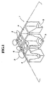
- the grippers 14 move rightward from the position shown by the solid line toward the rearing chambers 4 and grip the good seedlings 2a, and then the grippers 14 move upwardly and go across over the receiving member 35. Thereafter, the grippers 14 reach the position shown by the imaginary line in Fig. 7, and then move leftward in Fig. 9 while the solid mediums 6 of the good seedlings 2a are supported by the receiving member 35. Thus, the grippers 14 transfer the good seedlings 2a to the transferring device 17 and return to the solid line position (see Fig. 7) again.
- the taking-out device 15 is provided with a mechanism as shown in Figs. 6 through 9.
- each gripper 14 is supported by a shaft 36 through a coupler 37 at a certain pitch.
- the position of the coupler 37 is adjustable relative to the shaft 36.
- the shaft 36 is supported by a lateral bar 38 through a vertical member 39.
- Two guide bars 40 are connected to both sides of the lateral bar 38, and each guide bar 40 passes through a block member 41 so that the guide bar 40 is slidable relative to the block member 41.
- Two block members 41 at both sides of the lateral bar 38 are connected to each other by a connecting member 42 which is in confrontation with the lateral bar 38.
- the connecting member 42 and the lateral bar 38 are connected to each other by two air cylinders 43, 44 which are connected in series.
- the grippers 14 are moved rightward from the position (reference position) shown by the solid line to the position (on the right side of the reference position) shown by the imaginary line when the air cylinder 43 is in a retreated condition, the grippers 14 are moved leftward to the position (on the left side of the reference position) shown by the imaginary line when both the air cylinders 43, 44 are in an extended condition in Fig. 7.
- a vertical guide bar 45 extending vertically is fixedly secured to one side of the block member 41.
- a roller 46 is rotatably provided on the rear side of the block member 41.
- a lateral guide member 47 having a guide groove 47a for guiding the roller 46 in a horizontal direction.
- Vertical guide rods 48 are attached to both side ends of the lateral guide member 47, each vertical guide member 48 is fitted with the bearing member 49 which is vertically provided on the base plate 8R.
- the vertical guide rod 48 has a lower end to which a bracket 50 is attached.
- the bracket 50 and the frame 9 are connected to each other by the air cylinders 51, 52 which are connected in series.
- the grippers 14 are raised higher than the receiving member 35 while holding the good seedlings 2a. Thereafter, the air cylinders 43 and 44 are actuated and the grippers 14 are moved leftward across over the receiving member 35. Then the air cylinder 51 performs a retreated operation, the grippers 14 and the good seedlings 2a are lowered to the position shown by the imaginary line in Fig. 7, thereby supplying the good seedlings 2a to the receiving member 35.
- the clutch device 31 comprises a clutch body 53 connected to the air cylinder 33 for actuating the pusher 12, a sliding bar 54 slidably piercing through the clutch body 53, a bearing member 56 fixed to the left side end of the sliding bar 54 and supporting a roller 55, an engaging member 57 fixed to the right side end of the sliding bar 54, and a compression spring 58 accommodated in the clutch body 53 for urging the roller 55 so as to cause the roller 55 to move away from the clutch body 53.
- the roller 55 normally projects into the passageway of the cam 34 by urging force of the compression spring 58, and engaging portions 59 of the engaging member 57 are in confrontation with a plate 60 which is integrally formed on the bracket 50 provided on the lower portion of the vertical guide rod 48.
- the vertical guide rod 61 extending downwardly from the lower surface of the base plate 8R passes through the clutch body 53 vertically, and the clutch body 53 contacts a stopper 62 provided on the lower portion of the vertical guide rod 61, thereby causing the clutch body 53 to stop. Therefore, when pusher 12 projects upwardly and the cam 34 pushes the engaging member 57 rightward through the roller 55, the engaging portions 59 of the engaging member 57 are engaged with the plate 60. As a result, while the lateral guide member 47 and the grippers 14 are lifted, the pushers 12 are further lifted in the rearing chambers 4, thereby pushing out the good seedlings 2a from the rearing chambers 4 completely.
- the upper portion of the vertical guide bar 45 provided vertically on the block member 41 is connected to two sliders 65, spacedly provided with each other, through a bearing 64.
- Two sliders 65 are engaged with a guide rail 66 and connected to each other through a connecting plate 63, whereby the two sliders 65 move integrally along the guide rail 66.
- the guide rail 66 extends in a horizontal direction above the grippers 14, the guide rail 66 is attached to the backside of a beam member 68 supported by the base plate 8R through a vertical frame 67.
- a feed screw 69 is provided adjacent to and along the guide rail 66. As shown in Figs. 3 and 4, the feed screw 69 extends from the central upper position of a row of the grippers 14 to the transferring device 17, the feed screw 69 is provided between the bracket 70 and the bracket 71 which are fixed to the beam member 68. A nut 72 is engaged with the feed screw 69, and the nut 72 and the connecting plate 63 are connected by a connecting plate 73 (see Fig. 6).
- the motor 74 for driving the feed screw 69 is attached to the bracket 70. When the good seedlings 2a are received by the receiving member 35 as shown in Fig. 7, the motor 74 is rotated and the sliders 65 are moved leftward along the guide rail 66 in Figs. 3 and 4.
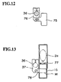
- a pushing plate 75 is connected to the left side end of the shaft 36 through a connecting member 76 so that the pushing plate 75 pushes the good seedlings 2a which have been already supplied to the transferring member 16 (describe later) when the grippers 14 are being moved leftward. Therefore, when the grippers 14 are moved leftward, the pushing plate 75 advances at the head of the grippers 14.
- the transferring device 17 is provided with the transferring member 16 which are engageable with the receiving member 35 or disengageable from the receiving member 35 as shown in Figs. 14 and 15.
- the transferring member 16 has a cross section corresponding to the solid medium 6 of the seedlings 2 so that the solid medium 6 is accommodated in the transferring member 16.
- the transferring member 16 is formed with a slit 77 for allowing stalks of the seedlings 2 to pass through and a slit 78 for allowing the grippers 14 to pass through.
- Supporting arms 79 are provided to maintain the shape of the transferring member 16.
- the transferring member 16 is connected to a forward end of a cylinder rod 80a of an air cylinder 80 provided on the base plate 8R so that the transferring member 16 is moved on the base plate 8R. Further, guide bars 81 and 82 are connected to the transferring member 16 so that the transferring member 16 is moved smoothly.
- the guide bar 82 is supported by a thrust bearing 83 provided horizontally on the base plate 8R, the guide bar 81 is nipped between upper and lower rollers 85 provided on the base plate 8R through a bracket 84.
- the grippers 14 gripping the good seedlings 2a are moved leftward, the grippers 14 together with the good seedlings 2a are entered into the transferring member 16 and stop when the tail end of the good seedlings 2a is introduced into the transferring member 16 as shown in Fig. 13. Thereafter, the air cylinder 80 is actuated, the transferring member 16 is disengaged from the receiving member 35 in a direction perpendicular to a longitudinal direction of the receiving member 35. Thus, the transferring member 16 receives the good seedlings 2a from the grippers 14, and the grippers 14 come out of the transferring member 16 through the slit 78.
- the row of the grippers 14 return to the original position by the reverse rotation of the motor 74, and the transferring member 16 returns to the original position to thus cause the transferring member 16 to engage with the receiving member 35.
- the pushing plate 75 comes out of the transferring member 16 through a vertical notch 86 formed on the left side of the transferring member 16 when the transferring member 16 is disengaged from the receiving member 35.
- the good seedlings 2a which have been already received in the transferring member 16 are pushed out therefrom while introducing the next row of the good seedlings 2a into the transferring member 16.
- the good seedlings 2a pushed out of the transferring member 16 are received on the delivery tray 3.
- the delivery tray feeding device 18 which feeds the delivery tray 3 in parallel to the feeding direction of the culture tray 1 as shown in Figs. 16 through 18.
- the delivery tray 3 is placed on a table 87 provided above the base plate 8L and fed by one pitch distance at every time when the good seedlings 2a are supplied into the groove 7 of the delivery tray 3.
- the table 87 is connected to two guide bars 88 and 89 extending horizontally above the base plate 8L.
- the guide bars 88 and 89 are fixed to the base plate 8L through brackets 90 and 91.
- the table 87 is movable in a back and forth direction by the ball screw mechanism, a screw 92 is disposed above the base plate 8L in parallel to the guide bars 88 and 89.
- the nut 93 engaged with the screw 92 is fixedly secured to the lower surface of the table 87.
- the screw 92 mounted on the base plate 8L is rotated by a motor 94.
- a shutter 95 is provided at the position where the left side end of the transferring member 16 confronts the table 87 (see Fig.
- the shutter 95 is adapted to shut the transferring member 16 when feeding the delivery tray 3.
- the shutter 95 is actuated by an air cylinder 96.
- On the left side of the table 87 there are provided an expander 97 for expanding the groove 7 of the delivery tray 3 as shown in Figs. 14 and 15, and a support 98 for supporting a leading good seedling 2a when pushed in the groove 7.
- the expander 97 has a groove corresponding to the groove 7 of the delivery tray 3, and connected to a forward end of a cylinder rod 99a of an air cylinder 99.
- the expander 97 is positioned at the left side of the table 87 before actuation of the air cylinder 99 and the expander 97 projects on the groove 7 when the air cylinder 99 is actuated.
- the support 98 is connected to a forward end of a cylinder rod 100a of an air cylinder 100, and the support 98 is moved from the right to the left side in the expander 97 which is inserted into the groove 7 by the actuation of the air cylinder 100.
- Two air cylinders 99 and 100 are fixed to a frame 101.
- the frame 101 is supported by the base plate 8L at the left side thereof through a bracket 102 and a horizontal pin 103, and the frame 101 is in contact with a stopper 104 fixed on the base plate 8L at the right side end thereof to thereby keep a horizontal posture.
- the frame 101 is connected to the base plate 8L through an air cylinder 105 at the central position thereof.
- the air cylinders 99 and 100 are inclined as shown in Fig. 18 by actuation of the air cylinder 101. Then, upon actuation of the two air cylinders 99, 100 the expander 97 and the support 98 are advanced toward the delivery tray 3. Thereafter, the air cylinder 105 performs a retreated operation to thereby cause the frame 101 to return to the horizontal posture, and the expander 97 is entered into the groove 7 of the delivery tray 3 to thus expand the groove 7.
- the shutter 95 is opened to form the exit of the transferring member 16, the pushing plate 75 and grippers 14 move in the transferring member 16 and push the good seedlings 2a out of the transferring member 16 to thereby supply them to the groove 7 of the delivery tray 3.
- the air cylinder 100 is caused to retreat gradually, the support 98 is being retracted while holding the head of the good seedlings 2a.
- the air cylinder 99 is caused to retreat, thereby pulling out the expander 97 from the groove 7.
- the good seedlings 2a remain in the groove 7 because the good seedlings 2a are supported by the support 98.
- the table 87 is driven and the delivery tray 3 is fed by one pitch in one direction.
- the good seedlings 2a are supplied into the groove 7.
- the culture tray 1 is placed on the base plate 8R.
- the engaging member 20 of the culture tray feeding device 10 moves leftward in Fig. 10 and the culture tray 1 is fed by one pitch.
- the front row of the seedlings 2 of the culture tray 1 are examined over three positions by the sensors 11, thereby judging the growth degree of the seedlings 2.
- the engaging member 20 is actuated and the culture tray 1 is further fed by one pitch in a forward direction.
- the pushers 12 push only the good seedlings 2a to thereby lift the good seedlings 2a at the upper portion of the rearing chambers 4.
- the cam 34 actuates the clutch device 31 by the lift of the pusher 12, the pushing device 13 is interconnected with the lifting mechanism of the grippers 14.
- the grippers 14 move horizontally toward the good seedlings 2a by a retreated actuation of the air cylinder 43, thereby gripping the solid medium 6 of the good seedlings 2a. Thereafter, the air cylinders 51 and 52 are actuated, the row of the grippers 14 gripping the good seedlings 2a are moved upwardly together with the block 41. At the same time, the pushers 12 are moved upwardly to push the good seedlings 2a out of the rearing chambers 4. The pushers 12 corresponding to the seedlings 2 having a bad quality are not actuated, thus the bad seedlings 2 remain in the rearing chambers 4.
- the grippers 14 go across over the receiving member 35 by the actuation of the air cylinders 43 and 44, and upon the actuation of the air cylinder 51 the grippers 14 are moved downwardly. Consequently, the good seedlings 2a are placed on the receiving member 35 while being gripped by the grippers 14.
- the nut 72 is moved by the rotation of the motor 74, the sliders 65 are moved along the guide rail 66 to convey the grippers 14 holding the good seedlings 2a toward the transferring member 16.
- the pushing plate 75 When the pushing plate 75 reaches the notch 86 of the transferring member 16, the row of the grippers 14 stops. Next, by the actuation of the cylinder 80, the transferring member 16 is moved horizontally to be away from the receiving member 35 and to cause the grippers 14 to disengage from the good seedlings 2a. At that time, the pushing plate 75 comes out of the transferring member 16 through the notch 86.
- the row of the grippers 14 returns to the original position by the reverse rotation of the motor 74, and the transferring member 16 returns to the original position where the transferring member 16 is communicated with the receiving member 35.
- the grippers 14 convey the next row of the good seedlings 2a to the transferring member 16, the pushing plate 75 pushes out the good seedlings 2a which have already been supplied to the transferring member 16.
- the good seedlings 2a pushed out of the transferring member 16 are supplied to the groove 7 of the delivery tray 3 on the table 87.
- the number of the seedlings 2 supplied to the groove 7 is not uniform due to occurrence of the bad seedlings, however, the number of the seedlings 2 is detected by the sensors 11 and computed by a computer (not shown), pushing actuation is repeated until a predetermined number of the seedlings 2 are supplied to the groove 7 of the delivery tray 3.
- the expander 97 expands the groove 7 of the delivery tray 3, the support 98 becomes in a standby condition to push the good seedlings 2a by the forward end of the support 98. Thereafter, the shutter 95 is opened to form the exit of the transferring member 16, the pushing plate 75 and the grippers 14 move in the transferring member 16, the good seedlings 2a in the transferring member 16 are pushed out and supplied to the delivery tray 3. Further, by the actuation of the air cylinder 100 in synchronization with the above operation, the support 98 moves back while supporting the leading seedling 2a.
- the expander 97 is pulled out of the groove 7 by the retreated actuation of the air cylinder 97. At this time, since the good seedlings 2a are supported by the support 98, the good seedlings 2a remain in the groove 7.
- the good seedlings 2a are successively supplied into the grooves 7 of the delivery tray 3.
- seedling can be automatically and rapidly transferred from the culture tray to the delivery tray without man power.
- the seedlings can be automatically sorted in accordance with the quality of the seedlings.
- the sensor means examine whether the seedlings are good or bad in quality, the quality of the seedlings can be accurately judged.
Landscapes
- Life Sciences & Earth Sciences (AREA)
- Soil Sciences (AREA)
- Environmental Sciences (AREA)
- Cultivation Receptacles Or Flower-Pots, Or Pots For Seedlings (AREA)
- Breeding Of Plants And Reproduction By Means Of Culturing (AREA)
Claims (9)
- Vorrichtung zur Auswahl von Setzlingen und zur Übertragung derselben, wobei folgendes vorgesehen ist:
eine erste Eingabevorrichtung (10) zum intermittierenden Eingeben eines Aufziehtabletts (1) mit einer Vielzahl von Reihen von Aufziehkammern (4) zum Aufziehen von Setzlingen (2) wobei die Aufziehkammer (4) im Boden derselben ein Loch (5) aufweist;
Sensormittel zur Überprüfung der Qualität der Setzlinge (2); eine Schubvorrichtung (13) um die Setzlinge (2) mit guter Qualität nach oben zu schieben, wobei die Schubvorrichtung (3) eine Vielzahl von Schubmitteln oder Schubelementen (12) aufweist, die in die entsprechenden Löcher (5) der Aufziehkammern (4) eingesetzt sind;
eine Herausnehmvorrichtung (15) zum Herausnehmen der Setzlinge (2) die von den Aufziehkammern (4) nach oben gestoßen wurden;
eine Übertragungsvorrichtung (17) zur Aufnahme der aus den Aufziehkammern (4) herausgenommenen Setzlinge (2) und zur Übertragung derselben zu einem Liefertablett (3);
eine zweite Eingabevorrichtung zum intermittierenden Eingeben eines Liefertabletts (3) mit einer Vielzahl von Nuten (7) zur Aufnahme einer Reihe von Setzlingen (2);
Führungsmittel (97), die entfernbar in die Nut des Liefertabletts (3) einsetzbar sind um die Einführung der erwähnten Reihe von Setzlingen (2) in die Nut (7) zu erleichtern. - Vorrichtung zur Auswahl von Setzlingen und zur Übertragung derselben gemäß Anspruch 1, wobei die erste Eingabevorrichtung (10) intermittierend das Aufziehtablett (1) eingibt, und zwar um einen Satz entsprechend einem Intervall zwischen zwei benachbarten Reihen von Aufziehkammern (4).
- Vorrichtung zur Auswahl von Setzlingen und zur Übertragung derselben gemäß Anspruch 1 oder 2, wobei die Sensormittel eine Reihe von Sensoren (11) aufweisen, die überprüfen können, ob eine Reihe von Setzlingen (2) von guter oder schlechter Qualität ist.
- Vorrichtung zur Auswahl von Setzlingen und zur Übertragung derselben gemäß einem der Ansprüche 1 bis 3, wobei der Sensor (11) den erwähnten Setzling (2) an einer Vielzahl von höheren Positionen des Setzlings (2) überprüft.
- Vorrichtung zur Auswahl von Setzlingen und zur Übertragung derselben gemäß einem der Ansprüche 1 bis 4 wobei die Schubvorrichtung (12) zwei Positionen einnehmen kann, so daß der durch die Schubvorrichtung (12) Schub ausgesetzte Setzling (2) in der Aufziehkammer (4) bleibt, und sodann wird der Setzling (2) vollständig aus der Aufziehkammer (4) herausgestoßen.
- Vorrichtung zur Auswahl von Setzlingen und zur Übertragung derselben gemäß einem der Ansprüche 1 bis 5, wobei die Herausnahmevorrichtung (15) eine Reihe von Greifern (14) aufweist um eine Reihe von Setzlingen (2) zu ergreifen und sie in einer Richtung der Reihe von Setzlingen (2) zu transportieren.
- Vorrichtung zur Auswahl von Setzlingen und zur Übertragung derselben gemäß einem der Ansprüche 1 bis 6 wobei ferner eine Kupplungsvorrichtung (31) vorgesehen ist, welche die Schubvorrichtung (13) und die Herausnahmevorrichtung (15) derart verbindet, daß die Greifer (14) zusammen mit den Schubmitteln bzw. der Schubvorrichtung (12) angehoben werden.
- Vorrichtung zur Auswahl von Setzlingen und zur Übertragung derselben gemäß einem der Ansprüche 1 bis 7 wobei die Übertragungsvorrichtung (17) ein Übertragungsglied (16) aufweist, welches eine Reihe von Setzlingen (2) von der Herausnahmevorrichtung (15) empfängt und die empfangene Reihe von Setzlingen (2) zu dem Liefertablett (3) überträgt, wenn die nächste Reihe von Setzlingen (2) in das Übertragungsglied (16) geschoben wird.
- Vorrichtung zur Auswahl von Setzlingen und zur Übertragung derselben gemäß einem der Ansprüche 1 bis 8 wobei die zweite Eingabevorrichtung (18) das Liefertablett (3) intermittierend um eine Stufe oder einen Satz entsprechen einem Intervall zwischen zwei benachbarten Nuten (7) des Liefertabletts (3) eingibt.
Applications Claiming Priority (4)
| Application Number | Priority Date | Filing Date | Title |
|---|---|---|---|
| JP333584/90 | 1990-11-30 | ||
| JP33358490 | 1990-11-30 | ||
| JP3197975A JPH053734A (ja) | 1990-11-30 | 1991-08-07 | 培養苗選別積替装置 |
| JP197975/91 | 1991-08-07 |
Publications (2)
| Publication Number | Publication Date |
|---|---|
| EP0488256A1 EP0488256A1 (de) | 1992-06-03 |
| EP0488256B1 true EP0488256B1 (de) | 1996-07-17 |
Family
ID=26510690
Family Applications (1)
| Application Number | Title | Priority Date | Filing Date |
|---|---|---|---|
| EP91120329A Expired - Lifetime EP0488256B1 (de) | 1990-11-30 | 1991-11-27 | Vorrichtung zum Auswählen von Sämlingen und zum Überführen derselben |
Country Status (3)
| Country | Link |
|---|---|
| US (1) | US5257889A (de) |
| EP (1) | EP0488256B1 (de) |
| JP (1) | JPH053734A (de) |
Families Citing this family (16)
| Publication number | Priority date | Publication date | Assignee | Title |
|---|---|---|---|---|
| JPH07169740A (ja) * | 1993-12-14 | 1995-07-04 | Nec Corp | マイクロ波プラズマ処理装置 |
| EP0758524A1 (de) * | 1995-08-11 | 1997-02-19 | Chong-Loung Houng | Sämlingschale und Maschine zum Verpflanzen von Sämlingen |
| NL1001762C2 (nl) * | 1995-11-28 | 1997-05-30 | Beekenkamp Plantenkwekerij B V | Werkwijze en inrichting voor het vullen van een houder. |
| US6212821B1 (en) * | 1999-05-10 | 2001-04-10 | Kieran L. Adam | Automatic plant selector |
| US6134939A (en) * | 1999-07-02 | 2000-10-24 | Hms Products | Toolless quick release of transfer bar |
| US7984583B2 (en) * | 2001-01-24 | 2011-07-26 | Tagawa Greenhouse Enterprises, Llc | Plant punch methods and apparatus |
| WO2002058455A1 (en) * | 2001-01-24 | 2002-08-01 | Tagawa Greenhouses, Inc. | Plant growing system to maximize transplant yield |
| DE10239001B3 (de) * | 2002-08-26 | 2004-02-05 | Karl Berner | Anordnung von Jungpflanzen, Vorrichtung zur Herstellung einer solchen Anordnung, Pflanzvorrichtung für derart angeordnete Jungpflanzen und Verfahren zum Pflanzen eng am Boden wachsender Pflanzen |
| JP2006080337A (ja) * | 2004-09-10 | 2006-03-23 | Seiwa Electric Mfg Co Ltd | 部品移送装置 |
| US7793944B2 (en) | 2004-12-28 | 2010-09-14 | Nok Corporation | Sealing device |
| CA2645772A1 (en) * | 2007-12-05 | 2009-06-05 | Tagawa Greenhouse Enterprises, Llc | Collapsible support apparatus and methods |
| NL2003715C2 (nl) * | 2009-10-27 | 2011-04-28 | Visser S Gravendeel Holding | Verwerkingssyteem voor planthouders. |
| CN102239804B (zh) * | 2011-05-03 | 2012-10-24 | 中国农业大学 | 一种自动取苗手爪机构及其取苗方法 |
| KR101376234B1 (ko) * | 2012-06-07 | 2014-04-01 | 대한민국 | 결주포트 제거유닛 및 이를 포함하는 재배포트 치상장치 |
| EP3020270A4 (de) * | 2013-07-10 | 2017-03-15 | Tsubakimoto Chain Co. | Pflanzenumtopfungsvorrichtung |
| CN113303061A (zh) * | 2021-07-14 | 2021-08-27 | 江西省农业科学院农业工程研究所 | 一种蔬菜移栽机自动喂苗装置 |
Family Cites Families (17)
| Publication number | Priority date | Publication date | Assignee | Title |
|---|---|---|---|---|
| US3722719A (en) * | 1970-04-10 | 1973-03-27 | Packard Instrument Co Inc | Method of and apparatus for sample vial transferring and changing |
| US3849932A (en) * | 1973-06-06 | 1974-11-26 | J Adams | Plant starting apparatus |
| US4213273A (en) * | 1978-07-28 | 1980-07-22 | Gravi-Mechanics Co. | Field transplant systems and methods and components thereof |
| FI69542C (fi) * | 1979-02-02 | 1986-03-10 | Serlachius Oy | Foerfarande och apparat foer matning av plantceller i en planteringsmaskin |
| SE446421B (sv) * | 1980-06-13 | 1986-09-15 | Stora Kopparbergs Bergslags Ab | Sett att byta odlingsenheter i elastiska krukor samt anordning for genomforande av settet |
| US4443151A (en) * | 1980-07-09 | 1984-04-17 | Bud Antle, Inc. | Automatic soil plug loader and feeder |
| US4454829A (en) * | 1981-05-07 | 1984-06-19 | Sena Gil A | Automatic plant setting apparatus |
| GB2176984B (en) * | 1985-07-05 | 1989-07-26 | Hamilton Design Ltd T W | Soil plug release apparatus |
| US4869637A (en) * | 1986-08-27 | 1989-09-26 | Bud Antle, Inc. | Plant transfer mechanism |
| KR950011710B1 (ko) * | 1986-11-21 | 1995-10-09 | 반 윙거덴 아트 | 배양구를 이용하여 식물을 증식시키는 장치 및 방법 |
| NL8800040A (nl) * | 1988-01-08 | 1989-08-01 | Visser S Gravendeel Holding | Inrichting voor het aangrijpen van van een plant voorziene kluiten. |
| US4998945A (en) * | 1988-12-14 | 1991-03-12 | National Research Development Corporation | Transplanting equipment |
| WO1990010377A1 (en) * | 1989-03-07 | 1990-09-20 | Williames Hi-Tech International Pty. Ltd. | Seedling transfer arrangement |
| GB2228910A (en) * | 1989-03-08 | 1990-09-12 | British Res Agricult Eng | Increasing the spacing between receptacles of an endless conveyor |
| CA1321924C (en) * | 1989-09-29 | 1993-09-07 | Edwin R. Mayne | Plug seedling extractor and method of using same |
| CA2028290C (en) * | 1989-11-01 | 1996-12-17 | Aart Van Wingerden | Tray, apparatus and method for propagating, growing and handling plants |
| EP0457405A3 (en) * | 1990-05-14 | 1992-05-27 | Hawe Elektrotraktie Transportsystemen B.V. | Establishment for pricking out plants |
-
1991
- 1991-08-07 JP JP3197975A patent/JPH053734A/ja active Pending
- 1991-11-27 US US07/798,719 patent/US5257889A/en not_active Expired - Fee Related
- 1991-11-27 EP EP91120329A patent/EP0488256B1/de not_active Expired - Lifetime
Also Published As
| Publication number | Publication date |
|---|---|
| JPH053734A (ja) | 1993-01-14 |
| EP0488256A1 (de) | 1992-06-03 |
| US5257889A (en) | 1993-11-02 |
Similar Documents
| Publication | Publication Date | Title |
|---|---|---|
| US5257889A (en) | Apparatus for selecting seedlings and transferring the same | |
| US5676072A (en) | Apparatus for automatically planting seedlings taken from a hard seedling tray | |
| JPH0615393A (ja) | 熱交換器組立装置のパイプ挿入装置 | |
| JP5000135B2 (ja) | 自動化プランター | |
| CN116322338B (zh) | 用于将鱼自动地装载在保持设备上的设备和方法 | |
| US20030047090A1 (en) | High speed feeding apparatus for clamshell die cutter | |
| JP3516495B2 (ja) | 接木装置 | |
| JPH09224485A (ja) | 苗抜取チャック | |
| JP7202603B2 (ja) | 自動移植機および移植方法 | |
| JPH0615392A (ja) | 熱交換器組立装置におけるスタックピンホルダー循環装置 | |
| JPH0615391A (ja) | スタックピンホルダーへのスタックピン引抜・差込装置 | |
| JP3516496B2 (ja) | 接木装置 | |
| JPH08154485A (ja) | 接木装置における葉処理装置 | |
| JP3513235B2 (ja) | 接木装置における穂部運搬装置 | |
| JP3513240B2 (ja) | 接木装置 | |
| JP2816515B2 (ja) | 接ぎ木苗切断方法 | |
| JPS6216933A (ja) | 各種プレ−トの自動送り込み装置 | |
| CN209956358U (zh) | 一种饼干计数包装系统 | |
| JP2816516B2 (ja) | 接ぎ木苗供給装置 | |
| JPH09220537A (ja) | 苗判別用センシングコンベア | |
| JPH0446866B2 (de) | ||
| JPH10120187A (ja) | 物品取上げ装置 | |
| JPH07274717A (ja) | 接木装置 | |
| CA2121453A1 (en) | Apparatus for transplanting seedlings | |
| JP3394830B2 (ja) | 仮植装置 |
Legal Events
| Date | Code | Title | Description |
|---|---|---|---|
| PUAI | Public reference made under article 153(3) epc to a published international application that has entered the european phase |
Free format text: ORIGINAL CODE: 0009012 |
|
| AK | Designated contracting states |
Kind code of ref document: A1 Designated state(s): NL |
|
| 17P | Request for examination filed |
Effective date: 19921201 |
|
| 17Q | First examination report despatched |
Effective date: 19940218 |
|
| GRAH | Despatch of communication of intention to grant a patent |
Free format text: ORIGINAL CODE: EPIDOS IGRA |
|
| GRAH | Despatch of communication of intention to grant a patent |
Free format text: ORIGINAL CODE: EPIDOS IGRA |
|
| GRAA | (expected) grant |
Free format text: ORIGINAL CODE: 0009210 |
|
| AK | Designated contracting states |
Kind code of ref document: B1 Designated state(s): NL |
|
| PLBE | No opposition filed within time limit |
Free format text: ORIGINAL CODE: 0009261 |
|
| STAA | Information on the status of an ep patent application or granted ep patent |
Free format text: STATUS: NO OPPOSITION FILED WITHIN TIME LIMIT |
|
| 26N | No opposition filed | ||
| PGFP | Annual fee paid to national office [announced via postgrant information from national office to epo] |
Ref country code: NL Payment date: 20041126 Year of fee payment: 14 |
|
| PG25 | Lapsed in a contracting state [announced via postgrant information from national office to epo] |
Ref country code: NL Free format text: LAPSE BECAUSE OF NON-PAYMENT OF DUE FEES Effective date: 20060601 |
|
| NLV4 | Nl: lapsed or anulled due to non-payment of the annual fee |
Effective date: 20060601 |