EP0488115A2 - Bilderzeugungsgerät - Google Patents
Bilderzeugungsgerät Download PDFInfo
- Publication number
- EP0488115A2 EP0488115A2 EP91120068A EP91120068A EP0488115A2 EP 0488115 A2 EP0488115 A2 EP 0488115A2 EP 91120068 A EP91120068 A EP 91120068A EP 91120068 A EP91120068 A EP 91120068A EP 0488115 A2 EP0488115 A2 EP 0488115A2
- Authority
- EP
- European Patent Office
- Prior art keywords
- optical system
- transfer sheet
- encoder
- forming apparatus
- pulse signals
- Prior art date
- Legal status (The legal status is an assumption and is not a legal conclusion. Google has not performed a legal analysis and makes no representation as to the accuracy of the status listed.)
- Withdrawn
Links
- 230000003287 optical effect Effects 0.000 claims abstract description 26
- 238000000034 method Methods 0.000 claims description 3
- 238000001514 detection method Methods 0.000 description 3
- 239000006185 dispersion Substances 0.000 description 3
- 238000000926 separation method Methods 0.000 description 2
- 230000001360 synchronised effect Effects 0.000 description 2
- 230000008859 change Effects 0.000 description 1
- 238000010586 diagram Methods 0.000 description 1
- 230000000694 effects Effects 0.000 description 1
- 239000000203 mixture Substances 0.000 description 1
- 238000012986 modification Methods 0.000 description 1
- 230000004048 modification Effects 0.000 description 1
- 230000008569 process Effects 0.000 description 1
- 230000004044 response Effects 0.000 description 1
Images


Classifications
-
- G—PHYSICS
- G03—PHOTOGRAPHY; CINEMATOGRAPHY; ANALOGOUS TECHNIQUES USING WAVES OTHER THAN OPTICAL WAVES; ELECTROGRAPHY; HOLOGRAPHY
- G03G—ELECTROGRAPHY; ELECTROPHOTOGRAPHY; MAGNETOGRAPHY
- G03G15/00—Apparatus for electrographic processes using a charge pattern
- G03G15/50—Machine control of apparatus for electrographic processes using a charge pattern, e.g. regulating differents parts of the machine, multimode copiers, microprocessor control
-
- G—PHYSICS
- G03—PHOTOGRAPHY; CINEMATOGRAPHY; ANALOGOUS TECHNIQUES USING WAVES OTHER THAN OPTICAL WAVES; ELECTROGRAPHY; HOLOGRAPHY
- G03G—ELECTROGRAPHY; ELECTROPHOTOGRAPHY; MAGNETOGRAPHY
- G03G15/00—Apparatus for electrographic processes using a charge pattern
- G03G15/22—Apparatus for electrographic processes using a charge pattern involving the combination of more than one step according to groups G03G13/02 - G03G13/20
- G03G15/28—Apparatus for electrographic processes using a charge pattern involving the combination of more than one step according to groups G03G13/02 - G03G13/20 in which projection is obtained by line scanning
- G03G15/30—Apparatus for electrographic processes using a charge pattern involving the combination of more than one step according to groups G03G13/02 - G03G13/20 in which projection is obtained by line scanning in which projection is formed on a drum
- G03G15/305—Apparatus for electrographic processes using a charge pattern involving the combination of more than one step according to groups G03G13/02 - G03G13/20 in which projection is obtained by line scanning in which projection is formed on a drum with special means to synchronize the scanning optic to the operation of other parts of the machine, e.g. photoreceptor, copy paper
-
- G—PHYSICS
- G03—PHOTOGRAPHY; CINEMATOGRAPHY; ANALOGOUS TECHNIQUES USING WAVES OTHER THAN OPTICAL WAVES; ELECTROGRAPHY; HOLOGRAPHY
- G03G—ELECTROGRAPHY; ELECTROPHOTOGRAPHY; MAGNETOGRAPHY
- G03G15/00—Apparatus for electrographic processes using a charge pattern
- G03G15/65—Apparatus which relate to the handling of copy material
- G03G15/6555—Handling of sheet copy material taking place in a specific part of the copy material feeding path
- G03G15/6558—Feeding path after the copy sheet preparation and up to the transfer point, e.g. registering; Deskewing; Correct timing of sheet feeding to the transfer point
- G03G15/6561—Feeding path after the copy sheet preparation and up to the transfer point, e.g. registering; Deskewing; Correct timing of sheet feeding to the transfer point for sheet registration
- G03G15/6564—Feeding path after the copy sheet preparation and up to the transfer point, e.g. registering; Deskewing; Correct timing of sheet feeding to the transfer point for sheet registration with correct timing of sheet feeding
-
- G—PHYSICS
- G03—PHOTOGRAPHY; CINEMATOGRAPHY; ANALOGOUS TECHNIQUES USING WAVES OTHER THAN OPTICAL WAVES; ELECTROGRAPHY; HOLOGRAPHY
- G03G—ELECTROGRAPHY; ELECTROPHOTOGRAPHY; MAGNETOGRAPHY
- G03G2215/00—Apparatus for electrophotographic processes
- G03G2215/00362—Apparatus for electrophotographic processes relating to the copy medium handling
- G03G2215/00367—The feeding path segment where particular handling of the copy medium occurs, segments being adjacent and non-overlapping. Each segment is identified by the most downstream point in the segment, so that for instance the segment labelled "Fixing device" is referring to the path between the "Transfer device" and the "Fixing device"
- G03G2215/00405—Registration device
-
- G—PHYSICS
- G03—PHOTOGRAPHY; CINEMATOGRAPHY; ANALOGOUS TECHNIQUES USING WAVES OTHER THAN OPTICAL WAVES; ELECTROGRAPHY; HOLOGRAPHY
- G03G—ELECTROGRAPHY; ELECTROPHOTOGRAPHY; MAGNETOGRAPHY
- G03G2215/00—Apparatus for electrophotographic processes
- G03G2215/00362—Apparatus for electrophotographic processes relating to the copy medium handling
- G03G2215/00535—Stable handling of copy medium
- G03G2215/00556—Control of copy medium feeding
Definitions
- the present invention relates to an image forming apparatus such as a copying machine, etc. and more particularly relates to an image forming apparatus in which the adjustment of feeding start timing of a transfer sheet to the transfer section can be easily carried out.
- a home position switch which is installed in the vicinity of the starting position of the optical system detects passage of the optical system.
- the timing switch which is installed at the downstream side in the scanning direction of the home position switch detects the passage of the optical system.
- the fixing position of the home position switch is a certain index position at the scanning start of the optical system.
- the timing switch is used for synchronizing both the reading start of a document image by the optical system and the movement of the leading edge of the transfer sheet on which the document image is to be transferred.
- the distance between respective fixing positions of the home position switch and the timing switch is individually set on every copying machine according to the synchronization timing for synchronizing both the reading start and the movement of leading edge of the transfer sheet.
- the copying machine is provided with a resist clutch which can intermittentably connect a resist roller to start the feeding of a transfer sheet to the transfer section with the drive source thereof. Therefore, the operation start timing of the resist clutch corresponds to the distance between the fixing positions of the respective switches.
- the timing switch can be installed so as to be able to move in the scanning direction, and the adjustment of the operation start timing of the resist clutch can be carried out by changing the fixing position of the timing switch.
- the present invention has been made to solve such problems.
- an image forming apparatus comprising an optical system for exposing a document image to a light and scanning the document image, a home position switch for detecting the optical system when it goes to the vicinity of the starting position, and a resist roller for setting the feeding start timing of a transfer sheet to the transfer section, and reproducing the document image onto a transfer sheet, is composed so that an encoder can be connected to the drive system of the optical system and the resist roller can be started when the pulse signals, which come from the encoder, are counted from the time when the optical system passes through the home position switch reach an appointed value.
- the encoder starts outputting pulse signals at the same time as the optical system is driven. And the pulse signals are counted from the time when the optical system passes through the home position switch in the vicinity of the starting position thereof. Then, when the pulse signals thus counted reach an appointed value corresponding to the feeding start timing of a transfer sheet to the transfer section, the resist roller for setting the feeding start timing starts. Therefore, the feeding start timing can be adjusted only with the work for changing the appointed value.
- a copying machine 1 is provided with the first travelling section 2 on which a light source 21 and a mirror 22 are installed for exposing and scanning a document image of a document (not illustrated) placed on the document table 28 at the upper part of the machine body 20 in the scanning direction shown with an arrow F and the second travelling section 3 on which mirrors 23 and 24 guide the image light reflected from the document to the surface of a photosensitive drum 8 by way of a mirror 25.
- a home position switch 4 is mounted at the machine body side below the first travelling section 2.
- the home position switch 4 is disengageably engaged with a detecting end 6 projecting from the underside of the first travelling section 2.
- the home position switch 4 detects that the above first travelling section 2 has come to the vicinity of the start position thereof. Namely, the actual stationary position of the first travelling section 2 is in the left side from the position of the first travelling part 2 shown in Fig. 1.
- a developer 10 to develop the electrostatic latent image formed on the surface of the photosensitive drum 8 for the document image as toner image, a pair of the resist rollers 7 to set the feeding start timing of the transfer sheet S, and a transfer and separation charger 9 as transfer section to transfer the toner image on the photosensitive drum 8 onto a transfer sheet S and to separate the transfer sheet S from the photosensitive drum 8 after the transfer is completed are disposed at the surrounding of the above photosensitive drum 8.
- the above resist rollers 7 are intermittentably connected to the drive source (not illustrated) by way of the resist clutch 15 (Fig. 3) and are driven and rotated by operation of the above resist clutch 15.
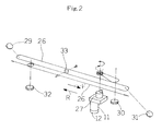
- a wire 26 to reciprocate the first traveling section 2 and the second travelling section 3 in the direction of arrows F and R is, as shown in Fig. 2, installed by being wound on the pulleys 29 through 31 rotatably installed at the body side, respectively.
- the above wire 26 can run by drive and rotation of the drive pulley 27 connected to the drive shaft of a motor 11.
- the first travelling section 2 is fixed at a part of the wire 26 by a fixing member 33.
- the second travelling section 3 is supported by the axis of an idle pulley 32 to which the wire 26 is wound, so that the second travelling section 3 can move in the direction of arrows F and R, and it is so composed that the second travelling section 3 can move over a half distance of movement of the first travelling section 2 at a half speed thereof.
- an encoder 12 is directly connected to the drive shaft of the motor 11 opposite to the drive pulley 27.
- the encoder 12 is not limited to be connected to the drive shaft of the motor 11 and, instead thereof, can be connected to the rotation axis of, for example, the pulleys 29 through 31 which can constitute the drive system together with the motor 11.
- the resist clutch 15 and the motor control section 16 to control the rotation of the motor 11 are connected to the signal output side of the main control section 13 which is mainly composed of a micro computer, and the home position switch 4, the encoder 12 and the non-volatile memory 14 are connected to the signal input side of the main control section 13.
- an appointed value of the above pulse signals for setting an adequate feeding start timing of the transfer sheet S is rewritably memorized, so that the leading edge of the document image as toner image on the photosensitive drum 8 and the leading edge of the transfer sheet S can be synchronized each other.
- the appointed value of the pulse signals can be inputted and set in advance by using a keyboard (not illustrated) of the machine body 20 and is stored in the non-volatile memory 14. Furthermore, in the preferred embodiment, the value of 5 which has been obtained through simple trial and error is set as the appointed value.
- the main control section 13 starts counting the pulse signals from the encoder 12 when the first travelling section 2 begins to move from the above actual stationary position and the detection end 6 thereof passes through the above home position switch 4, and it outputs the operation command signal to the resist clutch 15 when the counted value of the pulse signals reaches the appointed value (5).
- a copying machine 1 according to the preferred embodiment of the present invention is composed so as to be described above.
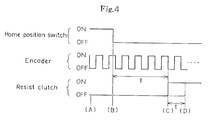
- the encoder 12 outputs pulse signals toward the main control section 13. And as the detection end 6 of the first travelling section 2 is engaged with the home position switch 4 (Time "A"), it is detected that the first travelling section 2 has come to the vicinity of the starting position, and the home position switch 4 outputs the detection signal toward the main control section 13.
- the main control section 13 counts the downstroke of the pulse signals from the encoder 12. And when the counted value of the pulse signals reaches the appointed value (5) (Time "C"), the above main control section 13 outputs an operation command signal to the resist clutch 15 and actuates the resist clutch 15, thereby causing the resist roller 7 to be started and causing the transfer sheet S to be fed between the photosensitive drum 8 and the transfer and separation charger 9 at a proper feeding start timing.
- the toner image corresponding to the document image on the photosensitive drum 8 is transferred onto the transfer sheet S with the leading edge of the transfer sheet S and the leading edge of the document image synchronized.
- the toner image is fixed by a fixing process (not illustrated), thereby causing the document image to be reproduced on the transfer sheet S.
- the resist roller 7 is composed so that it can be started at the same time as the counted value of the pulse signals reaches the appointed value (5).
- the resist roller 7 can be started at the time "D” elapsed by an appointed period of time t after the pulse signals reach the appointed value (Time "C").
- the period of time "T" between the time “B” and the time “C” corresponds to the time during which the first travelling section 2 scans at a constant speed between the fixing position of the home position switch 4 and the fixing position of a conventional timing switch 5 imaginarily shown with the two-dashed line in Fig. 1. Therefore, by properly changing the appointed value of the pulse signals, it is possible to carry out the adjustment of the feeding start timing of a transfer sheet S, which is equivalent to the case as well as accurately changing and adjusting the fixing position of the conventional timing switch 5 with mincing steps.
- the distance over which the first travelling section 2 travels in at the period of time "T" corresponds to the distance between the fixing position of the home position switch 4 and the fixing position of the conventional timing switch 5 imaginarily shown in the Figure, regardless of the scanning speed. Therefore, the adjustment of the feeding start timing of the transfer sheet S to the transfer section can be accurately carried out, regardless of equal or different magnification, in each of which the scanning speed is different.
- change of the appointed value of pulse signals can be carried out by inputting through the key board.
- a dip switch having a plurality of pins can be used and the appointed values having different numbers may be assigned to each of the pins thereof.
- the appointed value can be changed easily by a user's selection of either pin.
- the present invention can be carried into effect or embodied in different embodiments, without deviating from the spirits and substantial features thereof.
Landscapes
- Physics & Mathematics (AREA)
- General Physics & Mathematics (AREA)
- Engineering & Computer Science (AREA)
- Microelectronics & Electronic Packaging (AREA)
- Control Or Security For Electrophotography (AREA)
- Paper Feeding For Electrophotography (AREA)
- Exposure Or Original Feeding In Electrophotography (AREA)
- Optical Systems Of Projection Type Copiers (AREA)
Applications Claiming Priority (2)
| Application Number | Priority Date | Filing Date | Title |
|---|---|---|---|
| JP2327857A JPH04194918A (ja) | 1990-11-27 | 1990-11-27 | 画像形成装置 |
| JP327857/90 | 1990-11-27 |
Publications (2)
| Publication Number | Publication Date |
|---|---|
| EP0488115A2 true EP0488115A2 (de) | 1992-06-03 |
| EP0488115A3 EP0488115A3 (en) | 1992-11-25 |
Family
ID=18203753
Family Applications (1)
| Application Number | Title | Priority Date | Filing Date |
|---|---|---|---|
| EP19910120068 Withdrawn EP0488115A3 (en) | 1990-11-27 | 1991-11-25 | Image forming apparatus |
Country Status (3)
| Country | Link |
|---|---|
| US (1) | US5355196A (de) |
| EP (1) | EP0488115A3 (de) |
| JP (1) | JPH04194918A (de) |
Cited By (1)
| Publication number | Priority date | Publication date | Assignee | Title |
|---|---|---|---|---|
| GB2286154A (en) * | 1994-01-31 | 1995-08-09 | Lexmark Int Inc | Printer accumulator roller synchronization with image size adjustment |
Family Cites Families (16)
| Publication number | Priority date | Publication date | Assignee | Title |
|---|---|---|---|---|
| JPS5474749A (en) * | 1977-11-28 | 1979-06-15 | Ricoh Co Ltd | Control system of copying machine by microcomputer |
| DE2852060A1 (de) * | 1977-12-02 | 1979-06-13 | Canon Kk | Bilderzeugungsgeraet |
| US4260241A (en) * | 1978-05-17 | 1981-04-07 | Canon Kabushiki Kaisha | Copying apparatus |
| JPS5865456A (ja) * | 1981-10-14 | 1983-04-19 | Minolta Camera Co Ltd | 可変倍転写型複写機 |
| US5239341A (en) * | 1983-11-25 | 1993-08-24 | Canon Kabushiki Kaisha | Image processing apparatus having variable magnification control |
| DE3612349A1 (de) * | 1985-04-16 | 1986-10-16 | Sharp K.K., Osaka | Kopiergeraet |
| JPS629373A (ja) * | 1985-07-05 | 1987-01-17 | Sharp Corp | 複写装置 |
| US4878110A (en) * | 1986-08-15 | 1989-10-31 | Konishiroku Photo Industry Co., Ltd. | Color image processing apparatus which accurately registers multiple color images by counting pulses from a timer reset by a drum index signal |
| US5130748A (en) * | 1986-09-11 | 1992-07-14 | Fuji Xerox Co., Ltd. | Control unit of copying machines |
| JP2549377B2 (ja) * | 1987-04-07 | 1996-10-30 | 株式会社リコー | 静電複写機 |
| JPH01134472A (ja) * | 1987-11-20 | 1989-05-26 | Sharp Corp | 複写機 |
| US4952985A (en) * | 1987-11-27 | 1990-08-28 | Minolta Camera Kabushiki Kaisha | Electrophotographic copying apparatus with monitoring of scanning speed |
| JPH02144572A (ja) * | 1988-11-25 | 1990-06-04 | Minolta Camera Co Ltd | 複写装置 |
| DE69019016T2 (de) * | 1989-02-17 | 1995-10-05 | Canon Kk | Bilderzeugungsgerät. |
| JPH0336063A (ja) * | 1989-07-03 | 1991-02-15 | Seiko Epson Corp | ページプリンタ、及び印刷装置 |
| US5047800A (en) * | 1989-09-14 | 1991-09-10 | Minolta Camera Kabushiki Kaisha | Image recording apparatus |
-
1990
- 1990-11-27 JP JP2327857A patent/JPH04194918A/ja active Pending
-
1991
- 1991-11-25 EP EP19910120068 patent/EP0488115A3/en not_active Withdrawn
-
1993
- 1993-08-12 US US08/105,779 patent/US5355196A/en not_active Expired - Fee Related
Cited By (2)
| Publication number | Priority date | Publication date | Assignee | Title |
|---|---|---|---|---|
| GB2286154A (en) * | 1994-01-31 | 1995-08-09 | Lexmark Int Inc | Printer accumulator roller synchronization with image size adjustment |
| GB2286154B (en) * | 1994-01-31 | 1997-04-16 | Lexmark Int Inc | Accumulator roller synchronization with image size adjustment |
Also Published As
| Publication number | Publication date |
|---|---|
| EP0488115A3 (en) | 1992-11-25 |
| US5355196A (en) | 1994-10-11 |
| JPH04194918A (ja) | 1992-07-14 |
Similar Documents
| Publication | Publication Date | Title |
|---|---|---|
| EP0030282B1 (de) | Elektrofotographischer Kopierer mit variablem Vergrösserungsverhältnis und Kontrolle des Abtastschlittens | |
| US4540927A (en) | Two speed step motor driving apparatus for copying machines | |
| US4655585A (en) | Image forming apparatus | |
| US6009292A (en) | Image reader | |
| EP1261193B1 (de) | Vorrichtung und Verfahren zur Steuerung des Lesens einer weissen Referenzplatte in einem Bildlesegerät mit Einziehvorrichtung | |
| US4675741A (en) | Image forming apparatus | |
| US4627720A (en) | Variable magnification image projector | |
| US5355196A (en) | Micro computer controlled image forming apparatus | |
| EP0590533A1 (de) | Bilderzeugungsgerät | |
| US5097290A (en) | Scanner for scanning an object from a plurality of positions | |
| US4696564A (en) | Image forming apparatus | |
| JP4435448B2 (ja) | 画像読取装置および複写機 | |
| JPH042952B2 (de) | ||
| DE3500210A1 (de) | Einrichtung zum abtasten von dokumenten | |
| US4519697A (en) | Image forming apparatus | |
| JPS61190326A (ja) | 複写装置 | |
| JPH08160721A (ja) | 複写機の原稿読取装置 | |
| JP2783325B2 (ja) | 画像形成装置 | |
| JPS60162380A (ja) | 記録装置 | |
| JPH075480Y2 (ja) | 画像形成装置 | |
| JPS59142535A (ja) | 可変倍光学装置 | |
| JPS61151574A (ja) | 画像形成装置 | |
| JP2648628B2 (ja) | 移動体の制御方法 | |
| JPH0572581B2 (de) | ||
| JPS6221172A (ja) | 電子複写機 |
Legal Events
| Date | Code | Title | Description |
|---|---|---|---|
| PUAI | Public reference made under article 153(3) epc to a published international application that has entered the european phase |
Free format text: ORIGINAL CODE: 0009012 |
|
| 17P | Request for examination filed |
Effective date: 19911220 |
|
| AK | Designated contracting states |
Kind code of ref document: A2 Designated state(s): DE FR GB IT |
|
| PUAL | Search report despatched |
Free format text: ORIGINAL CODE: 0009013 |
|
| AK | Designated contracting states |
Kind code of ref document: A3 Designated state(s): DE FR GB IT |
|
| 17Q | First examination report despatched |
Effective date: 19941212 |
|
| STAA | Information on the status of an ep patent application or granted ep patent |
Free format text: STATUS: THE APPLICATION IS DEEMED TO BE WITHDRAWN |
|
| 18D | Application deemed to be withdrawn |
Effective date: 19950623 |