EP0488033B1 - Laserbearbeitungsgerät - Google Patents
Laserbearbeitungsgerät Download PDFInfo
- Publication number
- EP0488033B1 EP0488033B1 EP91119757A EP91119757A EP0488033B1 EP 0488033 B1 EP0488033 B1 EP 0488033B1 EP 91119757 A EP91119757 A EP 91119757A EP 91119757 A EP91119757 A EP 91119757A EP 0488033 B1 EP0488033 B1 EP 0488033B1
- Authority
- EP
- European Patent Office
- Prior art keywords
- mask
- work
- laser
- holes
- optical system
- Prior art date
- Legal status (The legal status is an assumption and is not a legal conclusion. Google has not performed a legal analysis and makes no representation as to the accuracy of the status listed.)
- Expired - Lifetime
Links
- 238000000034 method Methods 0.000 title claims abstract description 138
- 230000008569 process Effects 0.000 title claims abstract description 119
- 230000003287 optical effect Effects 0.000 claims abstract description 169
- 238000005259 measurement Methods 0.000 claims abstract description 66
- 230000005855 radiation Effects 0.000 claims abstract description 13
- 238000012545 processing Methods 0.000 claims description 57
- 238000005286 illumination Methods 0.000 claims description 56
- 230000005540 biological transmission Effects 0.000 claims description 25
- 238000001816 cooling Methods 0.000 claims description 12
- 238000007599 discharging Methods 0.000 claims description 9
- 238000003860 storage Methods 0.000 claims description 7
- 230000031700 light absorption Effects 0.000 claims description 5
- 239000000498 cooling water Substances 0.000 claims description 4
- 238000003491 array Methods 0.000 claims description 2
- 238000007493 shaping process Methods 0.000 claims 4
- 230000007246 mechanism Effects 0.000 description 24
- 241000907506 Israel turkey meningoencephalomyelitis virus Species 0.000 description 21
- 230000015572 biosynthetic process Effects 0.000 description 18
- 238000001914 filtration Methods 0.000 description 10
- 239000007788 liquid Substances 0.000 description 10
- 238000009826 distribution Methods 0.000 description 8
- 238000010586 diagram Methods 0.000 description 6
- 230000003247 decreasing effect Effects 0.000 description 4
- 239000000463 material Substances 0.000 description 4
- 230000004044 response Effects 0.000 description 4
- 239000004642 Polyimide Substances 0.000 description 3
- 230000005856 abnormality Effects 0.000 description 3
- 229910052782 aluminium Inorganic materials 0.000 description 3
- XAGFODPZIPBFFR-UHFFFAOYSA-N aluminium Chemical compound [Al] XAGFODPZIPBFFR-UHFFFAOYSA-N 0.000 description 3
- 230000008859 change Effects 0.000 description 3
- 230000000694 effects Effects 0.000 description 3
- 239000013307 optical fiber Substances 0.000 description 3
- 230000010355 oscillation Effects 0.000 description 3
- 229920001721 polyimide Polymers 0.000 description 3
- 238000006243 chemical reaction Methods 0.000 description 2
- 238000004519 manufacturing process Methods 0.000 description 2
- 230000004048 modification Effects 0.000 description 2
- 238000012986 modification Methods 0.000 description 2
- 239000002952 polymeric resin Substances 0.000 description 2
- 229920003002 synthetic resin Polymers 0.000 description 2
- 241000820057 Ithone Species 0.000 description 1
- 230000002238 attenuated effect Effects 0.000 description 1
- 238000009835 boiling Methods 0.000 description 1
- 239000000919 ceramic Substances 0.000 description 1
- 230000006835 compression Effects 0.000 description 1
- 238000007906 compression Methods 0.000 description 1
- 238000011109 contamination Methods 0.000 description 1
- 230000008602 contraction Effects 0.000 description 1
- 238000012937 correction Methods 0.000 description 1
- 230000001419 dependent effect Effects 0.000 description 1
- 238000001514 detection method Methods 0.000 description 1
- 238000005530 etching Methods 0.000 description 1
- 229910052736 halogen Inorganic materials 0.000 description 1
- 150000002367 halogens Chemical class 0.000 description 1
- 230000006872 improvement Effects 0.000 description 1
- 239000012535 impurity Substances 0.000 description 1
- 230000002452 interceptive effect Effects 0.000 description 1
- 238000012423 maintenance Methods 0.000 description 1
- 229910052751 metal Inorganic materials 0.000 description 1
- 239000002184 metal Substances 0.000 description 1
- 239000000203 mixture Substances 0.000 description 1
- 238000000465 moulding Methods 0.000 description 1
- 238000006303 photolysis reaction Methods 0.000 description 1
- 229920002492 poly(sulfone) Polymers 0.000 description 1
- 230000009467 reduction Effects 0.000 description 1
- 230000035939 shock Effects 0.000 description 1
Images


Classifications
-
- B—PERFORMING OPERATIONS; TRANSPORTING
- B23—MACHINE TOOLS; METAL-WORKING NOT OTHERWISE PROVIDED FOR
- B23K—SOLDERING OR UNSOLDERING; WELDING; CLADDING OR PLATING BY SOLDERING OR WELDING; CUTTING BY APPLYING HEAT LOCALLY, e.g. FLAME CUTTING; WORKING BY LASER BEAM
- B23K26/00—Working by laser beam, e.g. welding, cutting or boring
- B23K26/02—Positioning or observing the workpiece, e.g. with respect to the point of impact; Aligning, aiming or focusing the laser beam
- B23K26/04—Automatically aligning, aiming or focusing the laser beam, e.g. using the back-scattered light
- B23K26/042—Automatically aligning the laser beam
- B23K26/043—Automatically aligning the laser beam along the beam path, i.e. alignment of laser beam axis relative to laser beam apparatus
-
- B—PERFORMING OPERATIONS; TRANSPORTING
- B23—MACHINE TOOLS; METAL-WORKING NOT OTHERWISE PROVIDED FOR
- B23K—SOLDERING OR UNSOLDERING; WELDING; CLADDING OR PLATING BY SOLDERING OR WELDING; CUTTING BY APPLYING HEAT LOCALLY, e.g. FLAME CUTTING; WORKING BY LASER BEAM
- B23K26/00—Working by laser beam, e.g. welding, cutting or boring
- B23K26/02—Positioning or observing the workpiece, e.g. with respect to the point of impact; Aligning, aiming or focusing the laser beam
- B23K26/04—Automatically aligning, aiming or focusing the laser beam, e.g. using the back-scattered light
-
- B—PERFORMING OPERATIONS; TRANSPORTING
- B23—MACHINE TOOLS; METAL-WORKING NOT OTHERWISE PROVIDED FOR
- B23K—SOLDERING OR UNSOLDERING; WELDING; CLADDING OR PLATING BY SOLDERING OR WELDING; CUTTING BY APPLYING HEAT LOCALLY, e.g. FLAME CUTTING; WORKING BY LASER BEAM
- B23K26/00—Working by laser beam, e.g. welding, cutting or boring
- B23K26/02—Positioning or observing the workpiece, e.g. with respect to the point of impact; Aligning, aiming or focusing the laser beam
- B23K26/06—Shaping the laser beam, e.g. by masks or multi-focusing
- B23K26/064—Shaping the laser beam, e.g. by masks or multi-focusing by means of optical elements, e.g. lenses, mirrors or prisms
- B23K26/066—Shaping the laser beam, e.g. by masks or multi-focusing by means of optical elements, e.g. lenses, mirrors or prisms by using masks
-
- B—PERFORMING OPERATIONS; TRANSPORTING
- B41—PRINTING; LINING MACHINES; TYPEWRITERS; STAMPS
- B41J—TYPEWRITERS; SELECTIVE PRINTING MECHANISMS, i.e. MECHANISMS PRINTING OTHERWISE THAN FROM A FORME; CORRECTION OF TYPOGRAPHICAL ERRORS
- B41J2/00—Typewriters or selective printing mechanisms characterised by the printing or marking process for which they are designed
- B41J2/005—Typewriters or selective printing mechanisms characterised by the printing or marking process for which they are designed characterised by bringing liquid or particles selectively into contact with a printing material
- B41J2/01—Ink jet
- B41J2/135—Nozzles
- B41J2/16—Production of nozzles
- B41J2/162—Manufacturing of the nozzle plates
-
- B—PERFORMING OPERATIONS; TRANSPORTING
- B41—PRINTING; LINING MACHINES; TYPEWRITERS; STAMPS
- B41J—TYPEWRITERS; SELECTIVE PRINTING MECHANISMS, i.e. MECHANISMS PRINTING OTHERWISE THAN FROM A FORME; CORRECTION OF TYPOGRAPHICAL ERRORS
- B41J2/00—Typewriters or selective printing mechanisms characterised by the printing or marking process for which they are designed
- B41J2/005—Typewriters or selective printing mechanisms characterised by the printing or marking process for which they are designed characterised by bringing liquid or particles selectively into contact with a printing material
- B41J2/01—Ink jet
- B41J2/135—Nozzles
- B41J2/16—Production of nozzles
- B41J2/1621—Manufacturing processes
- B41J2/1632—Manufacturing processes machining
- B41J2/1634—Manufacturing processes machining laser machining
Definitions
- the present invention relates to a laser process apparatus comprising the features if the preamble part of claim 1 suitable for a hole forming machine using a laser, which machine is developed for mainly processing ink discharge orifices in an ink-jet head.
- a laser process apparatus comprising the features of the preamble part of claim 1 is known from US-A- 4 758 703.
- Holes having a predetermined shape and size are formed in a work using a laser beam in consideration of high process precision of the laser beam.
- the process precision of ink discharge orifices of an ink-jet head used in a printer, connected to a computer or a wordprocessor, for printing (recording) data by discharging an ink in a predetermined pattern directly influences an ink discharge amount, a discharge direction, and the like. For this reason, the holes must be processed very carefully.
- the above-mentioned ink-jet head is employed especially in a bubble-jet type recording head for discharging an ink by utilizing heat energy, of ink-jet recording methods.
- a typical arrangement and principle of a bubble-jet type recording apparatus are disclosed in, e.g., U.S. Patent Nos. 4,723,129, 4,740,796, and the like, and can be applied to either of a so-called on-demand type or continuous type.
- An on-demand type bubble-jet recording method will be exemplified below.
- Electro-thermal converters are arranged in correspondence with a sheet or a liquid channel, which holds a liquid (ink), and are caused to generate heat energy according to drive signals, thus causing film boiling on a heat application surface of a recording head. Consequently, bubbles having a one-to-one correspondence with the drive signals are formed in the liquid (ink), and the liquid (ink) is discharged in the form of liquid droplets from discharge orifices by growth and contraction of the bubbles.
- the drive signal to be applied is preferably a pulse signal, as disclosed in U.S. Patent Nos. 4,463,359 and 4,345,262.
- a temperature rise rate of the heat application surface conditions disclosed in U.S. Patent No. 4,313,124 are preferably employed.
- the ink-jet head is constituted by a combination of discharge orifices, a liquid channel (a linear liquid channel or a right-angled liquid channel), and electro-thermal converters.
- a heat application portion may be arranged on a bent region, as disclosed in, e.g., U.S. Patent Nos. 4,558,333 and 4,459,600.
- the ink-jet head may be arranged as follows. That is, a slit common to a plurality of electro-thermal converters may be used as a discharge portion of the electro-thermal converters, as disclosed in, e.g., Japanese Patent Laid-Open No.
- each recording head described in the above-mentioned specifications assures a length corresponding to a predetermined width by combining a plurality of recording heads.
- a single recording head may have a length corresponding to the predetermined width (the width of a maximum recording medium, which can be used in recording of a recording apparatus).
- the ink-jet head may be arranged as a chip type head, which is attached to an apparatus main body to attain electrical connections (for electro-thermal converters), and to be able to be supplied with an ink, or as a cartridge type head provided to a recording head itself.
- a laser process apparatus for radiating laser light onto a work through a mask formed with holes each having a predetermined shape.
- laser light is radiated on a mask formed with a plurality of arrays of holes so as to project laser beam spots similar to the holes formed in this mask onto a work to be processed, thereby forming holes in the work.
- This mask is arranged to be able to finely adjust its positions in the height and lateral directions, so that laser light to be radiated includes all the holes of the mask.
- the position adjustment is manually performed, and the adjustment result is visually confirmed.
- the laser light intensity varies depending on radiation positions. For this reason, even when laser light is radiated through holes having the same shape, holes formed in the work undesirably have different shapes depending on the beam radiation positions. Therefore, the position adjustment of the mask is performed by actually processing a work, and confirming the states of formed holes.
- the present invention has been made in consideration of the above-mentioned problems, and has as its first object to provide a laser process apparatus, which can simultaneously form a desired number of uniform holes in a work.
- the present invention provides a laser process apparatus, in which a plurality of holes each having a predetermined shape are formed in a work upon radiation of light from a laser, comprising a mask, in which a plurality of predetermined small holes are formed in correspondence with the plurality of holes to be formed in the work, and which allows laser light from said laser to pass through said small holes thereof toward the work, a projection optical system for projecting a mask image emerging through said mask onto the work, a first illumination optical system for illuminating the work from a side of said laser, a second illumination optical system for illuminating the work from a side of the work opposite to the side where said laser is arranged, wherein said laser is adapted to emit light having a wavelength in a light absorption wavelength range of said work, which further comprises a position measurement system for measuring a work position which comprises an optical system and at least one position detector, and which is arranged at a side of the work opposite to a side where said laser is arranged, and moving means for moving the
- the present invention provides a hole forming process position aligning method used when a plurality of holes are formed at predetermined process positions on a process surface of a work using laser light having a wavelength in a light absorption wavelength range of said work, comprising the radiation step of converting the laser light into desired light beams in correspondence with the plurality of holes to be formed, and radiating the light beams onto the process positions on the process surface, the reference value defining step of defining central positions of at least two light beams radiated oh the process surface as position reference values, the measurement step of measuring the process positions, irradiated with said at least two light beams, on the process surface of the work, the calculation step of calculating position shift amounts between the process positions and the reference positions by comparing the measured process positions with the corresponding position reference values, and the moving step of moving the work on the basis of the calculated position shift amounts.
- the laser process apparatus further comprises fixing means for fixing the mask.
- the fixing means comprises a mask holder and a mask press, which sandwich the mask therebetween to support it, a plurality of aligning reference holes are formed in the mask, a plurality of reference pins corresponding to the plurality of reference holes formed in the mask are arranged on one of the mask holder and the mask press, and a plurality of reference holes similar to the plurality of reference holes formed in the mask are formed in the other one of the mask holder and the mask press.
- the laser process apparatus since the laser process apparatus according to the second embodiment of the present invention has the above-mentioned arrangement, when the mask is fixed, the reference pins are inserted in the reference holes formed in the mask, so that the mask can be aligned with either of the mask holder or the mask press formed with the reference pins. Therefore, as long as the mask holder or the mask press formed with the reference pins is located at a predetermined position, a processed state of a work using the exchanged mask can be quickly checked using an industrial television.
- a laser process apparatus which forms holes in a work according to a desired pattern shape, further comprises a mask holder for arranging the mask on an optical axis of laser light emitted from the laser light source, a mask holder which is arranged to cover a portion, excluding the mask pattern, of the mask on the side of the light source, a mask press for fixing the mask to the mask holder, and mask cooling means, arranged in the mask holder, for cooling the mask.
- the laser process apparatus since the laser process apparatus according to the third embodiment of the present invention has the above-mentioned arrangement, laser light is radiated on a work through the mask formed with the mask pattern having the desired shape so as to form holes in the work according to the mask pattern.
- the mask When laser light is radiated on a portion, other than the mask pattern, of the mask upon passing of the laser light, the mask reflects or absorbs the laser light.
- the laser light absorbed by the mask is converted into heat, and the heat causes a temperature rise of the mask.
- the portion, other than the mask pattern, of the mask is covered with the mask holder, the amount of the laser light radiated on the mask can be decreased, and the mask cooling means provided to the mask holder can suppress the temperature rise of the mask.
- the hole formation process position aligning method according to the second aspect of the present invention is executed, the position shift amounts between the central positions of at least two light beams radiated on a process surface of a work, and process positions radiated with the light beams on the process surface are calculated, and a work is moved based on the calculated position shift amounts, thereby aligning the process positions with the central positions of the light beams.
- a plurality of process positions can be simultaneously aligned.
- a laser process apparatus which is arranged to form a plurality of holes at predetermined process positions on the process surface of the work, additionally comprises storage means for storing position reference values indicating central positions of at least two holes of processed holes formed in a processed work, an observation optical system for, when the process surface of the non-processed work is illuminated by the transmission illumination system corresponding to the first illumination optical system, observing the process positions corresponding to the at least two processed holes, and for, when the at least two processed holes of the processed work are illuminated by the reflection optical system corresponding to the second illumination optical system, observing the at least two processed holes, an image processing system for obtaining position measurement values indicating the process positions observed by the observation optical system, and for obtaining hole central positions of the at least two processed holes observed by the observation optical system, and a control system for calculating position shift amounts by comparing the position measurement values obtained by the image processing system with the corresponding position reference values stored in the storage means, driving the moving stage implementing the
- the laser process apparatus since the laser process apparatus according to the fifth embodiment of the present invention has the above-mentioned arrangement, laser light emitted from the laser light source is converted into laser beams corresponding to a plurality of holes to be formed, and a non-processed work is moved on the basis of the position shift amounts between the central positions of at least two processed holes of the work formed with the holes by these laser beams, and process positions on a work corresponding to these processed holes. Therefore, a plurality of process positions of the non-processed work can be simultaneously aligned with the laser beams. Furthermore, since the laser beams are radiated on the process surface of the non-processed work, a plurality of holes can be simultaneously formed.
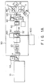
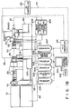
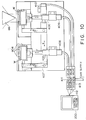
- Figs. 1A and 1B are respectively a plan view and a side view of the laser hole forming process machine according to this embodiment.
- ultraviolet laser light P emitted from a laser light source 10 using an excimer laser is radiated on a mask 30 for converting the light into a desired pattern in correspondence with holes to be formed.
- a mask image passing through the mask 30 is radiated on a work W such as an ink-jet head, which is attached to be aligned in a direction perpendicular to the laser light P, thereby forming holes serving as ink discharge orifices in the work W.
- the laser hole forming process machine of this embodiment comprises an illumination optical system 20 for uniformly radiating the laser light P emitted from the laser light source 10 onto the mask 30, a mask position adjustment mechanism 32 for adjusting the position of the mask 30, a moving stage 120 comprising an aligning jig 40 to which the work W is attached, a projection optical system 50 for projecting a mask image emerging through the mask 30 onto the work W, a transmission illumination system 60 for radiating illumination light onto the work W from the side of the laser light source 10 when the work W is aligned, and reflection optical systems 74 and 84 (see Fig. 13A) for radiating illumination light from a direction opposite to that of the transmission illumination system 60.
- Measurement optical systems 70 and 80 for respectively focusing optical images formed by radiating illumination light onto the work W by the transmission illumination system 60, and the reflection optical systems 74 and 84 on two industrial televisions (to be abbreviated to as ITVs hereinafter) 71 and 81 are mounted on an apparatus frame 90.
- the laser hole forming process machine comprises two image processing systems 208 and 209 for fetching image signals of images focused on the ITVs 71 and 81, and executing signal processing associated with the aligning operation of the work W, and a control system 200, having a display 201, for controlling the emission operation of the laser light source 10 and the aligning operation of the work W.
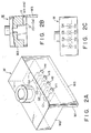
- Figs. 2A to 2C are respectively a perspective view, a sectional view, and a front view showing the structure of the work W after hole formation.
- the work W is set to constitute an ink-jet head for discharging an ink in a predetermined pattern in, e.g., a printer. More specifically, the work W is constituted by a top member W 2 in which 64 or 128 groove holes G [Figs. 2A to 2C illustrate only four groove holes G 1 , G 2 , G 3 , and G 4 for the sake of illustrative and descriptive conveniences] serving as ink flow paths are juxtaposed in the longitudinal direction, and a planar member W 3 (the rear surface thereof is defined as a process surface W 1 ) serving as an orifice plate.
- Holes H [Figs. 2A to 2C illustrate only four holes H 1 , H 2 , H 3 , and H 4 for the sake of illustrative and descriptive conveniences] to be formed in the work W and serving as discharge orifices are formed in the planar member W 3 in one or a plurality of operations by laser light passing through the mask 30 in correspondence with the groove holes G (G 1 , G 2 , G 3 , and G 4 ).
- Two works W are mounted on the aligning jig 40, so that the process surfaces W 1 of the planar members W 3 face the laser light source 10. Thereafter, these works are aligned with respect to laser light.
- the work W is aligned as follows. That is, the central positions of two predetermined groove holes (e.g., groove holes at two ends) are caused to coincide with the central positions of two holes, corresponding to these two groove holes, of a plurality of holes formed in the work W in the previous process step.
- the central positions of these holes and groove holes are obtained by executing signal processing of image signals of images of the holes and groove holes observed by the ITVs 71 and 81 in the image processing systems 208 and 209.
- the central positions of the holes are stored as reference values in a RAM 202 [see Fig. 1B] as a storage means through the control system 200.
- the central positions of the groove holes are compared with the reference values to calculate a shift amount of the work W, and the calculated shift amount is supplied to a moving system controller 206 as a moving amount.
- the moving stage 120 is driven through the moving system controller 206, thereby causing the centers of the holes of the work W to coincide with the centers of the groove holes.
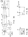
- laser light (200 Hz, 50 W, 28 mm x 6 mm) emitted from the laser light source 10 is incident on the illumination optical system 20, and thereafter, radiates the mask 30.
- the laser light spot pattern is converted into a circular pattern using a combination of an elliptic mask 21, a concave cylindrical lens 22, and a convex cylindrical lens 23.
- the elliptic mask 21 having a mask hole 211 (Fig. 3B) is arranged at the center of the laser light P, which is emitted to have a 28 mm x 6 mm rectangular spot pattern.
- the spot pattern of the laser light P is converted into an elliptic pattern by the elliptic mask 21.
- the concave cylindrical lens 22 is arranged to expand the laser light in a direction of the small width (6 mm side).
- the laser light is then converted to parallel light P 2 having a circular spot pattern with a spot size of 28 mm by the convex cylindrical lens 23.
- the circular parallel light P 2 having the spot size of 28 mm is converted into circular parallel light P 3 having a spot size of 20 mm by a beam compressor, which is constituted by arranging convex and concave lenses 24 and 25, so that the ratio f 3 : f 4 of their distances f 3 and f 4 to the focal point position is set to be 28 : 20 so as to have the same focal point position.
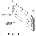
- the split beams illuminate mask holes 31, which are aligned on a 19-mm line formed on the mask 30, and have a pattern of a hole to be formed, at a predetermined inclination angle, as shown in Fig. 6.
- the mask 30 is prepared by forming the mask holes 31, having a diameter four times that of a hole to be formed, in a 25- ⁇ m thick Ni plate by etching.
- the mask 30 is mounted on the mask position adjustment mechanism 32 while being clamped between a mask holder 33 and a mask press 34.
- the position of the mask 30 is adjusted according to an instruction supplied from the control system 200 through an interface 205.
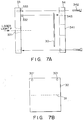
- Fig. 7A is a side view showing a schematic structure of the mask 30, and Fig. 7B is a plan view of the mask 30 in Fig. 7A.
- the plurality of mask holes 31 each having a diameter of 120 ⁇ m are formed in line in the central portion of the mask 30.
- two reference holes 301 are formed in the mask 30. These reference holes 301 are set to serve as aligning reference when the mask 30 is mounted, and are defined by through holes each having a diameter of 2 mm.
- the mask holder 33 having a thickness of 8 mm is fixed on a mask holder aligning jig 325 standing upright on the mask position adjustment mechanism 32 (to be described later).
- a window 331 formed to extend along the aligning direction of the mask holes 31 is formed in the central portion of the mask holder 33. Since the laser light P is focused on the mask 30 by the illumination optical system 20, the window 331 is tapered narrower toward the side of the mask 30.
- Mask aligning reference pins 332 each having a diameter of 2 mm are arranged on the mask holder 33 at positions corresponding to the reference holes 301 formed in the mask 30.
- a window 341 for projecting the laser light P passing through the mask holes 31 onto the work W is formed in the central portion of the mask press 34 having a thickness of 7 mm.
- Reference holes 343, each having a diameter of 2 mm, for aligning the mask 30 are arranged on the mask press 34 at positions corresponding to the reference holes 301 and the reference pins 332.
- the mask 30 is aligned by inserting the reference pins 332 in the reference holes 343 via the reference holes 301.
- the tolerance between the reference pin 332 and the reference hole 301 must be ⁇ 10 ⁇ m or less.
- fixing screws 342 are screwed in fixing screw holes 333, thereby completely fixing the mask holder 33 and the mask press 34 to each other.
- the mask 30 can also be fixed.
- the reference holes 301 and 343, and the reference pins 332 need only two-dimensionally align the mask 30. Therefore, the numbers of these holes and pins are not limited as long as two or more holes and pins are provided.
- the reference pins 332 are arranged on the mask holder 33, and the reference holes 343 are formed in the mask press 34.
- the reference holes may be formed in the mask holder 33, and the reference pins may be arranged on the mask press 34.
- a flow path 334 through which cooling water for cooling the mask 30 flows, is formed in a bent state over at least substantially the entire surface portion contacting the mask 30.
- cooling water supplied from a cooling water supply source 300 shown in Figs. 1A and 1B is supplied to flow from a flow-in port 335 toward a flow-out port 336.
- a window 326 for allowing the laser light to pass therethrough is formed in the mask holder aligning jig 325 to extend in the same direction as the window 331 of the mask holder 33.
- the window 326 is formed, so that its height is larger than the height, on the side of the laser light source, of the window 331 of the mask holder 33.
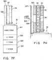
- the mask holder aligning jig 325 stands upright on the mask position adjustment mechanism 32 constituted by a goniostage 321, an X stage 322, a Z stage 323, and a Y stage 324, so that the position of the jig 325 is adjustable.
- the stages 321 to 324 are respectively moved by independent motors 321a, 322a, 323a, and 324a, as shown in Fig. 7G.
- the motors 321a to 324a are driven by drive signals supplied, through the interface 205, from the control system 200 [Fig. 1B] connected to the image processing systems 208 and 209.
- the goniostage 321 is used for adjusting the mask position in the rotational direction having the laser optical axis as the center.
- the X stage 322 is used for adjusting the position of the mask 30 in the aligning direction of the mask holes 31.
- the Z stage 323 is used for adjusting the mask position in a direction perpendicular to the laser optical axis and the aligning direction of the mask holes 31.
- the Y stage 324 is used for adjusting the mask position in the direction of the laser optical axis. With these stages, the mask holes 31 formed in the mask 30 are adjusted to be located in the laser optical axis.
- a second mask 327 as a light-shielding plate formed with a window 328 for allowing laser light to pass therethrough may be arranged on the mask position adjustment mechanism 32 on the laser light source side of the mask holder aligning jig 325 to be separated from the mask holder aligning jig 325, as shown in Fig. 7H.
- the height of the window 328 formed in the second mask 327 is decreased to be smaller that of the window 326 of the mask holder aligning jig 325 so as to decrease the amount of laser light radiated on the mask holder 33, although the height depends on the forming position of the window 328.
- the height of the window 328 can be substantially the same as the height, on the laser light source side, of the window 331 of the mask holder 33.
- the temperature rise of the mask 30 can be suppressed.
- the temperature of the second mask 327 is considered to be increased since a larger amount of light than that on the mask holder 33 is radiated on the second mask 327.
- the second mask 327 is arranged to be separated from the mask holder aligning jig 325, the temperature rise of the second mask 327 will not influence the mask 30.
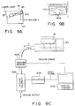
- the work W is placed on the aligning jig 40, and the aligning jig 40 is arranged on a table 902.
- the table 902 is arranged on a goniostage 903, a ⁇ stage 904, a Z stage 905, a Y stage 906, and an X stage 907. These stages are respectively moved by corresponding motors 903a to 907a, and the motors 903a to 907a are driven by the control system 200 in the same manner as in control of the mask position adjustment mechanism 32 shown in Fig. 7G.
- the moving stage 120 which can move the work W to an arbitrary position by these stages 903 to 907, can be constituted. More specifically, the moving stage 120 can be moved in a total of five axial directions, i.e., the laser optical axis direction (Y direction), an axial direction (Z direction) perpendicular to the laser optical axis and the aligning direction of the holes, the aligning direction (X direction) of the holes, and the rotational direction ( ⁇ Y direction) having the laser optical axis as a rotational axis.
- the moving stage 120 is operated according to an instruction supplied from the control system 200 through the moving system controller 206 so as to align the work W.
- the work W is mounted on the aligning jig 40, so that the process surface W 1 is inclined toward the laser light source 10.
- the aligning jig 40 comprises two sets of two vacuum holes 401 for holding two works W, as shown in Fig. 9B, and also comprises an abutting mechanism for fixing the works W chucked and held by the vacuum holes 401.
- a suction operation by a suction source (not shown) is performed by driving a vacuum solenoid 402 in response to a drive signal supplied from the control system 200 through an interface 204, thereby chucking and holding two works W by each two vacuum holes 401.
- the suction pressures of the vacuum holes are always detected by a vacuum sensor 403, and the control system 200 monitors the holding states of the works W on the basis of the detected pressures.
- the aligning jig 40 has a total of five aligning references 404, i.e., two points on the chucking/holding surface, and three points on the side surfaces of the work W.
- the works W are supplied onto the aligning jig 40 by an auto hand 100, the works W are held by vacuum suction.
- the works W are then abutted in the optical axis direction (a direction of an arrow Y in Fig. 10) of the laser light P by two abutting mechanisms 405 and 406 from the optical axis direction of the laser light P, and thereafter, are abutted in the hole aligning direction (a direction of an arrow X in Fig. 10) by an abutting mechanism 407 from the hole aligning direction, thereby fixing the two works W.
- the two abutting mechanisms 405 and 406 respectively correspond to the two works W held on the aligning jig 40.
- These abutting mechanism 405 and 406, and the abutting mechanism 407 in the hole aligning direction respectively open/close solenoid valves 411, 412, and 413 upon an instruction from the control system 200, thereby driving air cylinders 408, 409, and 410.
- the groove positions are measured as follows. That is, transmission illumination light Q 1 from the transmission illumination system 60 on the side of the laser light source 10 is radiated on the work W to cause optical images of the grooves to pass through the planar members W 3 , and the optical images are observed by the measurement optical systems 70 and 80 on the side opposite to the laser light source 10.
- the transmission illumination system 60 has an optical fiber 61 for guiding the transmission illumination light Q 1 toward the work W, and a 45° mirror 62, as shown in Fig. 11, so as to radiate the transmission illumination light Q 1 onto the work W.
- the optical fiber 61 is arranged, so that light emerging therefrom is perpendicular to the optical axis of the laser light P.
- the 45° mirror 62 is arranged, so that the transmission illumination light Q 1 guided by the optical fiber 61 is reflected in the same direction as the laser light P. Furthermore, the 45° mirror 62 is attached to an air cylinder 63, which is restricted in the rotational direction. Thus, the 45° mirror 62 can be moved to a position where the mirror does not shield the laser light upon emission of the laser light.
- a shutter 65 which shields output light, is moved in response to an instruction supplied from the control system 200 through the interface 204, thereby emitting the output light.
- the 45° mirror 62 can be similarly moved by driving the air cylinder 63 through a vacuum solenoid 64 in response to an instruction from the control system 200.
- the grooves to be observed are a second groove hole G 2 and a 63rd groove hole G 63 , which are inwardly neighboring grooves of those (a first groove hole G 1 and a 64th groove hole G 64 ) at two ends, as shown in Fig. 12.
- Optical images of these groove holes are reflected by a mirror 66, which has two reflection surfaces arranged on their optical paths, and are incident on the measurement optical systems 70 and 80 without interfering with each other, as shown in Fig. 11.
- optical systems 70 and 80 The structures of the measurement optical systems 70 and 80 will now be described.
- objective lenses 72 and 82 are arranged at destination positions of optical images reflected by the mirror 66.
- the 2/3" ITVs 71 and 81 which have a resolution of 500 x 480 pixels, and on which the optical images are focused, are arranged on the optical axes of the optical images transmitted through the objective lenses 72 and 82.
- Half mirrors 73 and 83 are arranged on the optical axes of the optical images between the objective lenses 72 and 82 and the ITVs 71 and 81. These half mirrors 73 and 83 reflect light components produced by the reflection optical systems 74 and 84 arranged on these reflection optical paths toward the mirror 66.
- transmission optical images formed by illuminating the work W by the transmission illumination system 60 are reflected by the mirror 66, and are then focused on the ITVs 71 and 81 through the half mirrors 73 and 83.
- light components produced from the reflection optical systems 74 and 84 are respectively reflected by the half mirrors 73 and 83, are then reflected by the mirror 66, and radiate the work W from the side opposite to the laser light source. In this manner, optical images reflected by the work W are reflected by the mirror 66, and are focused through the corresponding half mirrors 73 and 83.
- the reflection optical systems 74 and 84 are respectively provided with shutters 75 and 85 at their light output portions. When these shutters 75 and 85 are moved in response to an instruction supplied from the control system 200 through the interface 204, output light components emerge toward the half mirrors 73 and 83.
- the adjustment mechanisms 76 and 86 respectively comprise moving stages 762 and 862 used for adjusting the measurement optical systems 70 and 80 in the optical axis direction, moving stages 763 and 863 used for adjusting the measurement optical systems 70 and 80 in a direction perpendicular to a plane defined by the laser optical axis and the hole aligning direction, and moving stages 761 and 861 used for adjusting the measurement optical systems 70 and 80 in a direction perpendicular to a plane defined by the moving direction of the moving stages 762 and 862, and the moving direction of the moving stages 763 and 863.
- the measurement optical systems 70 and 80 respectively comprise auto-focus units 77 and 87.
- the auto-focus units 77 and 87 supply pieces of groove position information in the laser optical axis direction to the control system 200 so as to improve aligning precision after the measurement of the groove positions.
- the two optical images of the second groove hole G 2 and the 63rd groove hole G 63 of the work W which images are reflected by the mirror 66, are focused on the ITVs 71 and 81 at a x40 magnification and a resolution of 0.33 ⁇ m/pel through the objective lenses 72 and 82 and the half mirrors 73 and 83.
- Two output signals S1 from the ITVs 71 and 81 are respectively input to the two image processing systems 208 and 209 shown in Fig. 1B.
- the image processing systems 208 and 209 respectively obtain the two groove positions.
- An image signal of an image of the second groove hole G 2 displayed on the ITV 71 of the measurement optical system 70 is fetched (S501).
- image information fetched on the RAM a pixel, which is the ith one (0 ⁇ i ⁇ 499) in the horizontal direction, and is the jth one (0 ⁇ j ⁇ 479) in the vertical direction, is represented by (i,j), and its pixel data is represented by V(i,j) on an image fetching area having 500 pixels in the horizontal direction, and 480 pixels in the vertical direction.
- the pixel data V(i,j) represents brightness, and is expressed by 8-bit data ranging between 0 and 255 (0: black, 255: white).
- Fig. 15(a) shows the image of the groove hole G 2 displayed on the ITV 71.
- a line representing the profile of the groove hole G 2 is displayed in black.
- scratches which may be formed upon molding of the work W, are also displayed, and the fetched image signals also includes components representing the scratches.
- the image signal of the groove hole G 2 is subjected to filtering processing, thereby removing images of the scratches (S502).
- the slice level is determined in such a manner that the maximum and minimum values of all the pixel data are searched, and are averaged before the binarization processing.
- Figs. 16(c) and 16(d) show pixels within the range of i-2 to i+2 and j-2 to j+2 for the pixel (i.j).
- Fig. 16(d) shows a state wherein the brightness values of all the pixels within the searched range are "0". Therefore, upon execution of the above-mentioned filtering processing, the brightness value V(i,j) of the pixel (i,j) is set to be 1 in Fig. 16(c). On the other hand, the brightness value V(i,j) of the pixel (i,j) is set to be 0 in Fig. 16(d).
- Fig. 15(b) shows the image of the groove hole G 2 after the filtering processing.
- the Y coordinate of a jaw rest portion of the groove hole G 2 i.e., of a corner portion defined by the top member W 2 and the planar member W 3 in Fig. 2A, is obtained (S503).
- a sum V j of brightness values in units of lines is obtained by the following equation for all the pixels (500 x 480 pixels) of the ITV 71, which displays the image of the groove hole G 2 after the filtering processing.
- the graph of Fig. 15(d) shows the sums V j of the brightness values in units of lines in correspondence with lines.
- the minim brightness portion corresponds to a portion on the line of the jaw rest portion shown in Fig. 15(b).
- Fig. 15(e) is an enlarged view of the minimum brightness portion in the graph of Fig. 15(d).
- a minimum value V min in the sums V j of the brightness values in units of lines is obtained.
- a predetermined value F e.g. 10, 10 is added to the minimum value V min , and this sum is determined as a slice level.
- the Y coordinate corresponding to the middle point between two points crossing the graph is determined as a position yl of the jaw rest portion.
- the value a is preferably about 20 ⁇ m if the depth of the groove hole is assumed to be 40 ⁇ m.
- Fig. 15(f) shows the line yl + b expressed by a brightness value V(i,y +b).
- two dark portions points having low brightness values
- Fig. 15(g) shows an enlarged view of the dark portion.
- An X coordinate corresponding to the middle point ( X (X 1 + X 2 )/2 ) of the calculated coordinates X 1 and X 2 is determined as an X position of the groove hole G 2 (S507).
- the X position corresponds to the hole aligning direction (X direction)
- the Y position corresponds to a direction (Z direction) perpendicular to the laser optical axis and the hole aligning direction.
- the groove positions of the groove holes G 2 and G 63 are simultaneously obtained by the image processing systems 208 and 209.
- the groove positions of the groove holes G 2 and G 63 obtained by the image processing systems 208 and 209 as described above are supplied to the control system 200 through a cable S2 (RS232) and an interface 207.
- the control system 200 calculates shift amounts between the supplied groove position data and the reference values stored in advance in the RAM 202.
- the position of the second groove hole G 2 in the X and Z directions is represented by (X 2 ,Z 2 )
- the positions of the 63rd groove hole G 63 in the X and Z directions is represented by (X 63 ,Z 63 )
- a reference value corresponding to the groove hole G 2 is represented by (x 2 ,z 2 )
- a reference value corresponding to the groove hole G 63 is represented by (x 63 ,z 63 ).
- the distance between the optical axes of the position detection mechanisms of the measurement optical systems 70 and 80 is represented by D
- the distance between the two reference points indicated by the reference values is expressed by D + x 2 + x 63 . If X 2 » D and x 63 » D, the distance between the two reference points is D.
- the shift amounts for the three axes calculated based on the above-mentioned equations are input from the control system 200 to the moving system controller 206 as moving amounts of the work W.
- the moving system controller 206 drives the moving stage 120 through three drivers corresponding to the three axes on the basis of the calculated moving amounts.
- this aligning operation no adjustment is performed for two axes other than the three axes, i.e., the laser optical axis direction (Y direction), and a rotational direction ( ⁇ Z direction) having, as a rotational axis, an axis perpendicular to the laser optical axis and the hole aligning direction, since they can fall within given precision.
- moving amounts for the above two axes may be calculated on the basis of the differences between signal values from the auto-focus units 77 and 87 attached to the measurement optical systems 70 and 80, and the reference values stored in the RAM 202.
- the calculated moving amounts may be input from the control system 200 to the moving system controller 206, and the moving system controller 206 may move the moving stage 120 through two drivers corresponding to the two axes on the basis of the input moving amounts, thus adjusting the work position in these directions.
- the controller system 200 After the position of the work W is adjusted, the controller system 200 causes the laser light source 10 to emit light for a predetermined period of time (2 sec) through a cable S3 (RS232) and an interface 203. Thus, predetermined holes can be formed in the work W. Thereafter, calibration for hole positions and hole diameters is performed, as will be described later.
- the aligning jig 40 is moved to the position of the second work W, and holes are formed in the second work W in the same manner as in the first work W.
- the aligning jig 40 is moved to the process position of the first work W.
- the control system 200 drives the vacuum solenoid 402 to release the chucking state of the works W, and supplies an end signal to an auto hand (AH) controller 103 through a cable S4.
- AH auto hand
- the auto hand 100 has supply and delivery fingers. Upon reception of the end signal, the auto hand 100 delivers the processed works using the delivery fingers, and thereafter, supplies non-processed works to the aligning jig 40 of the hole forming process machine using the supply fingers.
- Each of the supply and delivery fingers of the auto hand 100 of this embodiment comprises two suction ports 101 and 102, as shown in Fig. 17, and can simultaneously supply or deliver two works.
- the printing performance must be controlled to a predetermined value.
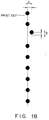
- the positional precision of the formed holes must fall within a predetermined range (e.g., ⁇ 2 ⁇ m).
- a variation in a direction (a direction of an arrow A) perpendicular to a plane defined between the hole aligning direction and the laser optical axis, a variation in the hole aligning direction (a direction of an arrow B), and a variation of hole diameters must be taken into consideration, as shown in Fig. 18.
- Fig. 18 shows printed dots formed by discharging an ink from an ink-jet head manufactured by using the work W after the hole forming process.
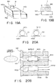
- a product (ink-jet head) manufactured using the work after the hole forming process will be described below with reference to Figs. 19A and 19B, and Figs. 20A and 20B.
- Figs. 19A and 19B are respectively a perspective view and a longitudinal sectional view showing an ink-jet head
- Figs. 20A and 20B are respectively a longitudinal sectional view and a cross-sectional view showing a portion around discharge orifices of the ink-jet head.
- the ink-jet head is formed by mounting the work W after the hole forming process on a heater board 143.
- heaters 143 n (only heaters 143 1 and 143 2 are illustrated) are juxtaposed on the heater board 143 in correspondence with the groove holes G n (only holes G 1 and G 2 are illustrated) of the work W.
- the work W is mounted on the heater board 143, so that the groove holes G n and the heaters 143 n coincide with each other.
- the holes H n formed in the work W serve as discharge orifices 141 n
- the groove holes G n communicating with the discharge orifices 141 n serve as ink flow paths
- the planar member W 3 serves as an orifice plate 142.
- An ink I is stored in the top plate W 2 .
- the heaters 143 n are connected to a printing drive unit (not shown) through wiring members 144 n , as shown in Fig. 20B, when the ink-jet head is assembled in a printing apparatus.
- the heater 143 1 is driven according to a drive signal from the printing drive unit so as to heat the ink I in the groove hole G 1 .
- a bubble is formed in the groove hole G 1 , and the ink on the discharge orifice 141 1 side from the bubble is caused to fly as a liquid droplet.
- a shift amount of the relative positional relationship between the positions of laser light (mask images) after the laser light passes through the mask 30, and the measurement optical systems 70 and 80 must be suppressed.
- the following calibration method is employed. That is, the positions of the formed holes are measured, and the measured positions are used as reference positions of the groove positions of the next work W to be subjected to hole formation.
- This calibration method uses the measurement optical systems 70 and 80, the reflection optical systems 74 and 84 attached to the measurement optical systems 70 and 80, and the image processing systems 208 and 209 for performing image processing of the signals S1 from the ITVs 71 and 81.
- the shutters 75 and 85 which shield output light beams from the reflection optical systems 74 and 84, are opened, and the output light beams are respectively reflected by the half mirrors 73 and 83 to propagate through the objective lenses 72 and 82. Thereafter, the output light beams are reflected by the mirror 66 so as to be radiated on the work W.
- Optical images which are reflected by the work W and represent the shapes of the formed holes, are focused on the ITVs 71 and 81, and image processing operations of the signals S1 from the ITVs 71 and 81 are executed by the image processing systems 208 and 209, thereby calculating the positions of the formed holes.
- the calculated values are transferred to the control system 200 through the cable S2 and the interface 207.
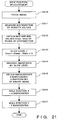
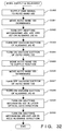
- the hole position measurement in the image processing systems 208 and 209 will be described below with reference to the flow chart shown in Fig. 21. Since the image processing systems 208 and 209 simultaneously measure the hole positions of the second hole H 2 and the 63rd hole H 63 by the same method, only one image processing system 208 will be described below.
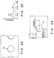
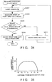
- FIG. 22 shows the image of the hole H 2 displayed on the ITV 71.
- the brightness values of all the pixels on the ITV 71 are expressed by 8-bit binary codes (0 to 255) in the same manner as in the above-mentioned measurement of the groove positions, and the frequency of the brightness values, i.e., the number of pixels having the same brightness values is checked within a range of all the pixels (S511).
- Fig. 23 shows the frequency of the brightness values. In Fig. 23, two peak values representing a dark portion of the hole H 2 and the remaining bright portion appear.
- V min A portion having a small value (V min ) represents the dark portion of the hole H 2 .
- Maximum and minimum values V max and V min of the brightness values corresponding to the peak values are obtained from this graph (S512).
- a slice level for binarizing image signals is calculated based on the obtained V max and V min using the following equation (S513):
- the slice level obtained in this manner is compared with the brightness values of pixels, thereby binarizing image signals (S514).
- a portion of the hole H 2 can be distinguished from the remaining portion, and the image of the hole H 2 can be formed upon binarization of the image signals, as shown in Fig. 24.
- the calculated X and Y barycenters are respectively determined as hole positions X and Y of the hole H 2 (S517).
- the hole positions of the two holes H 2 and H 63 are simultaneously obtained in the same manner as in the groove holes.
- the hole position X corresponds to the hole aligning direction
- the hole position Y corresponds to the direction perpendicular to the laser optical axis and the hole aligning direction.
- the position data of the holes H 2 and H 63 obtained in this manner are transferred to the control system 200.
- the control system 200 rewrites two values, i.e., a value corresponding to the hole aligning direction (X direction), and a value corresponding to the direction (Z direction) perpendicular to the laser optical axis and the hole aligning direction, which values are previously stored in the RAM 202, with the values representing the hole positions as reference positions.
- the work is moved based on the differences, as moving amounts, between these two values as reference values (x,z), and the values (X,Z) of the groove positions in the image processing.
- the areas of the holes considerably influence the printing performance (especially, the density), and it is important to make constant a variation of the areas, and an average value of the areas in terms of the performance.
- a hole is formed in the work W to have a tapered shape, so that a diameter on the input side of laser light (input diameter 162) is large, and a diameter on the output side of laser light (output diameter 161) is small.
- the taper angle is decreased, and the output diameter 161 is increased while the input diameter 162 is constant.
- the hole area is increased. The same applies to a case wherein the number of radiation pulses to a hole formation portion by laser light is changed.
- the hole diameter, the laser power density, and the number of radiation pulses have a close relationship therebetween.
- the excimer laser used as the laser light source emits light by pulse discharging. Therefore, a light amount per emission varies.
- the excimer laser is largely influenced by the gas concentration, the impurity concentration, and the application voltage in the laser, the service life of the optical systems, contaminations, and the like, resulting in unstable power.
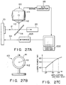
- a power sensor 110 comprising a power meter 111 having an aluminum mask 112, which has a mask hole 113 having a predetermined area, is arranged at the exit of the laser light P, and a beam splitter 114 having a reflectance of several % is arranged in the laser optical path, so that the laser light can be radiated on the aluminum mask 112.
- the output signal S5 from the power meter 111 is supplied to the control system 200 through an A/D converter 115.
- Fig. 27C shows the relationship between the application voltage to the laser light source 10, and the laser power.
- the power meter 111 may comprise either of a light amount measurement type meter or a heat measurement type meter.
- the hole area the area of the formed hole may be measured, and the application voltage to the laser light source 10 may be controlled based on the measured area so as to obtain a constant hole area.
- This area measurement uses the measurement optical systems 70 and 80, the reflection optical systems 74 and 84 attached to the measurement optical systems 70 and 80, the image processing systems 208 and 209 for performing image processing of the signals S1 from the ITVs 71 and 81, and the control system 200.
- the shutters 75 and 85 which shield the output light beams from the reflection optical systems 74 and 84, are opened, thus illuminating the work W from the sides of the objective lenses 72 and 82.
- Optical images which are reflected by the work W, and represent the shapes of formed holes, are focused on the ITVs 71 and 81 attached to the two measurement optical systems 70 and 80, and image processing operations of the signals S1 from these ITVs 71 and 81 are respectively executed by the image processing systems 208 and 209, thereby calculating the areas of the formed holes.
- the calculated values are transferred to the control system 200 through the cable S2 and the interface 207.
- predetermined values e 1 and e 2 are subtracted from the hole positions X and Y obtained as described above (S520, S521, S522).
- a predetermined value f in this embodiment, a value corresponding to 200 pixels
- the number of pixels indicating a dark portion in the binary image upon measurement of the hole positions is counted within this range (S523).
- the number of pixels of the hole portion is obtained, and is multiplied with a value h (in this embodiment, 0.33 ⁇ m x 0.33 ⁇ m) representing the area of one pixel, thereby obtaining the hole area (S524).
- the hole area data of the two holes H 2 and H 63 obtained in this manner are transferred to the control system 200.
- the control system 200 determines an application voltage to the laser light source 10 on the basis of a predetermined equation using the transferred hole area data, and transfers it to the laser light source 10 through the cable S3 and the interface 203. In this manner, the application voltage to the laser light source 10 upon process of the next work W is determined. With this method, a uniform hole area can be obtained.
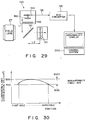
- an illumination light distribution on the mask 30 in the hole forming process is important. If the distribution varies, the hole diameters vary, resulting in printing nonuniformity.
- a beam splitter 191 is arranged between the field lens 27 and the mask 30, thereby reflecting 10% of the whole light amount in a direction perpendicular to the optical axis.
- a power measurement device 190 is arranged on the optical axis of the reflected light.
- the light-receiving surface of a line sensor 192 is arranged on the optical axis of the reflected light at a position equivalent to the position of the mask 30, and a filter 193 for shielding attenuated light and visible light is arranged on the optical path of the reflected light between the line sensor 192 and the beam splitter 191.
- the power measurement device 190 supplies an output from the line sensor 192, which output indicates an illumination light amount radiated on the mask 30, to the control system 200 through an amplifier 194 and an A/D converter 195.
- the distribution of light radiated on the first to 64th holes of the mask 30 is measured, and it is checked if the difference between Max and Min values shown in Fig. 30 falls within a predetermined value. If the difference falls outside the predetermined value, the control system 200 displays abnormality on the display 201, thus stopping the hole forming process machine.
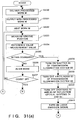
- first and second non-processed works W are supplied onto the aligning jig 40 by the auto hand 100 (S531).
- first and second works W are placed on the aligning jig 40, they are held by vacuum suction by the vacuum holes 401, and are then fixed by the abutting mechanisms 405, 406, and 407 (S532).
- the auto hand 100 comprises the two sets of fingers, i.e., the supply and delivery fingers, it can simultaneously perform delivery operations of two processed works W, and supply operations of two non-processed works W.
- the auto hand 100 holds two works, i.e., first and second non-processed works W to be subjected to hole formation next by vacuum suction using the supply fingers, and stands by above the aligning jig 40.
- the delivery fingers of the auto hand 100 hold the two processed works W by vacuum suction (S584).
- the supply fingers of the auto hand 100 are then moved to the work supply position on the aligning jig 40, and the auto hand 100 is moved downward (S585, S586).
- the vacuum chucking states of the first and second non-processed works W by the auto hand 100 are released (S587), thus transferring the first and second works W to the aligning jig 40.
- the first and second works W are held by vacuum suction through the vacuum holes 401 (S588). Furthermore, the abutting mechanism 407 is driven to abut the first and second works W from the laser optical axis direction (S589). Thereafter, the abutting mechanisms 405 and 406 corresponding to the first and second works W are driven to abut the works from the hole aligning direction (S590), thereby fixing the first and second works W supplied on the aligning jig 40.
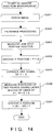
- the groove positions of the groove holes G 2 and G 63 of the first work W are measured by the image processing systems 208 and 209 (S533) by the above-described method shown in Fig. 14.
- the control system 200 compares the two measured groove positions, and reference values representing the corresponding hole positions, thereby determining if the shift amounts of the groove positions fall within predetermined standards (S534, S535). If the shift amounts fall outside the standards, the moving stage 120 is driven through the moving system controller 206 on the basis of the shift amounts, so that the groove positions can fall within the standards of the reference values (S536).
- step S533 and subsequent steps is repeated (S537) until the count value reaches a predetermined value (in this embodiment, 10). If the count value exceeds the predetermined value (10), an abnormality is displayed on the display 201 (S558), and the laser hole forming process machine is stopped. The control then waits for a restart instruction (S559).
- step S535 If it is determined in step S535 that the groove positions fall within the standards, the shutter 65 of the transmission illumination system 60 is driven to shield transmission illumination light Q 1 , and the air cylinder 63 is driven to cause the 45° mirror 62 to escape from the position on the laser optical axis (S538, S539).
- the shutters 75 and 85 of the reflection optical systems 74 and 84 are removed from the output optical paths of the reflection optical systems 74 and 84 (S540).
- the laser light source 10 is caused to emit light (S541), and after an elapse of 2 sec, the light emission is stopped (S542, S543). When the light emission is stopped, hole formation for the first work W is completed.
- the moving stage 120 In order to measure the central positions and areas of the holes formed in the first work W, the moving stage 120 is moved by a distance corresponding to the thickness of the planar member W 3 toward the laser light source in the laser optical axis direction (Y direction) (S544). This movement is made for the following reason. Since the hole positions and hole areas are measured by illuminating the first work W with illumination light beams from the reflection optical systems 74 and 84 on the side opposite to the laser light source, the focal points of the hole images on the ITVs 71 and 81 are shifted from the focal points of images of the groove holes formed by illuminating the first work W with the transmission illumination light Q 1 from the transmission illumination system 60 by a distance corresponding to the thickness of the planar member W 3 .
- the central positions and areas of the processed holes are measured by the methods shown in Figs. 21 and 28 (S545).
- the reference values of the hole positions stored in the RAM 202 are rewritten with the measured central positions of the processed holes, and an application voltage for driving the laser light source 10 is set in accordance with the measured areas of the processed holes (S546, S547).
- the moving stage 120 is moved in the hole aligning direction (X direction) (S548).
- the shutter 65 of the transmission illumination system 60 is driven to be removed from the position on the transmission illumination optical path, and the air cylinder 63 is driven to move the 45° mirror 62 of the transmission illumination system 60 onto the laser optical path (S549, S550).
- the shutter 75 of the reflection optical system 74 is driven to shield the output light from the reflection optical system 74 (S551).
- the moving stage 120 is moved by a distance corresponding to the thickness of the planar member W 3 in the laser optical axis direction (Y direction) (S552). Thereafter, the positions of the groove holes G 2 and G 63 are similarly measured (S553).
- the measured groove positions are compared with the reference values stored in the RAM 202 to determine if the shift amounts therebetween fall within the predetermined standards, in the same manner as in the first work W (S554, S555). If the measured groove positions fall outside the standards, the moving stage 120 is moved, so that the groove positions coincide with the central positions of the holes indicated by the reference values (S556). These operations (S553 to S556) are repeated up to a predetermined number of times (10 times) if the measured groove positions cannot fall within the standards (S557). If the number of times of these operations exceeds the predetermined value (10 times), an abnormality is displayed on the display 201 (S558), and the laser hole forming process machine is stopped. The control then waits for a restart instruction (S559).
- the same operations (S560 to S569) as in the operations (S538 to S547) for the first work W are executed to form holes in the second work W.
- the positions and areas of the holes are measured to rewrite the reference values in the RAM 202, which values indicate the hole positions, and an application voltage to the laser light source 10 is set in accordance with the hole areas.
- the moving stage 120 is moved in the hole aligning direction (X direction), thus returning the first work W to the initial position (S570).
- the shutter 65 of the transmission illumination system 60 is removed from the transmission illumination optical path, and the air cylinder 63 is driven to move the 45° mirror 62 onto the laser optical axis (S571, S572).
- the shutters 75 and 85 of the reflection optical systems 74 and 84 are driven to shield the output light beams from the reflection optical systems 74 and 84 (S573).
- the moving stage 120 is moved to a side opposite to the laser light source by a distance corresponding to the thickness of the planar member W 3 in the laser optical axis direction (Y direction) (S574). If non-processed works W remain, the operations in step S530 and subsequent steps are repeated to execute the hole forming process.
- the distribution of the laser light radiated on the mask holes 31 of the mask 30 may be measured using the power measurement device 190 (see Fig. 29).
- holes may be formed beforehand in a dummy member having the same shape as the work W, and the central positions of the holes may be measured and stored in advance in the RAM 202.
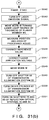
- the control system 200 causes the laser light source 10 to emit the laser light P (S601), thus forming holes in the work W.
- the holes are formed in the work W to be shifted according to the difference between the pre- and post-exchange mask positions. For this reason, the positions of the holes H 2 and H 63 formed on the left and right sides of the work W shown in Fig. 12 are checked in the sequence shown in the flow chart of Fig. 21 (S602).
- a horizontal shift amount in the measurement optical system 80 is represented by ⁇ x r
- a vertical shift amount is represented by ⁇ z r
- a horizontal shift amount in the measurement optical system 70 is represented by ⁇ x l
- a vertical shift amount is represented by ⁇ z l
- the ratio of the hole pitch on the work W to the hole pitch on the mask 30 is represented by n
- the interval between the right and left holes on the mask 30 is represented by L.
- the above-mentioned shift amounts can be corrected by moving the X stage 322, the Y stage 324, and the goniostage 321. More specifically, the X axis is moved by n ⁇ ( ⁇ x r + ⁇ x l )/2 (S603), the Z axis is moved by n ⁇ ( ⁇ z r + ⁇ z l )/2 (S604), and the ⁇ axis is moved by tan -1 ⁇ n ⁇ ( ⁇ z r - ⁇ z l )/L ⁇ (S605).
- the mask position can be almost corrected to the pre-exchange position.
- the hole positions may often fall outside the standards depending on the precision of the stages, the aligning precision of the mask holder 33, and the like after a single correction. For this reason, after the stages are moved, the positions of the holes are checked again (S606). Thereafter, the checking operations are repeated until the hole positions fall within the standards.
- the laser light source 10 is caused to emit the laser light P to form holes in the work W (S607).
- the areas of the holes H 2 and H 63 formed at the left and right sides of the work W are measured by the measurement optical systems 70 and 80 according to the sequence shown in the flow chart of Fig. 28 (S608).
- Fig. 26 shows the relationship between the laser light intensity and the area of a hole formed in the work W.
- Fig. 35 shows the energy intensity distribution of the laser light P on the mask 30 in the process. From these graphs, it can be estimated that the axis of the laser light P is offset to one, having a larger area, of the holes H 2 and H 63 formed at the left and right sides of the work W.
- the hole areas of the holes H 2 and H 63 are compared with each other to check if the comparison result falls within a predetermined range (S609). Thereafter, if the hole areas fall within the predetermined range, the positions of the holes H 2 and H 63 formed in the work W are stored (S610), thus ending the control sequence. However, if the comparison result falls outside the predetermined range, the mask 30 is moved by a predetermined amount (S611). The above-mentioned operations are repeated until the comparison result falls within the predetermined range.
- the position of the mask 30 can be aligned in the optical path of the laser light P to be balanced well.
- the mask 30 is set at a position different from that before adjustment, and the positions of holes formed in a work W are shifted, as a matter of course.
- the work W is moved according to the present positions of the holes H 2 and H 63 stored in step S610 in the flow chart of Fig. 34.
- the same process as that before the axis of the laser light P is shifted can be performed for the work W.
- the above-mentioned position adjustment of the mask 30 is performed when the mask is exchanged or when the laser optical axis is shifted.
- a variation in atmosphere which may cause a position shift, such as a temperature drift or vibration, is detected, and when the variation amount exceeds a predetermined amount, the position adjustment may be automatically executed.
- the position adjustment may be executed at predetermined time intervals, as a matter of course.
- the lenses 21 to 25 in the illumination optical system 20 are used to guide laser light to the fly-eye lens 26.
- the present invention is not limited to this arrangement.
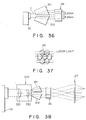
- the above optical system may be modified, as shown in Fig. 36 of another embodiment.
- prisms 311 and 312 for splitting laser light P emitted from a laser light source 10 into three beams in a direction perpendicular to a plane defined by the laser optical axis and a hole aligning direction are arranged.
- the three beams must be split at a predetermined interval in the direction perpendicular to the plane so as to coincide with the optical axes of a fly-eye lens 26. Since the fly-eye lens 26 is constituted by combining 6 ⁇ lenses, the optical axes of the lens 26 are separated by 5.2 mm in the direction perpendicular to the plane. Since the laser light has a spot size of 6 mm in the direction perpendicular to the plane, it can be split into three beams by 2 mm. Since the beams are originally separated by 2 mm, the beams must be further separated by 3.2 mm by the prisms 311 and 312.
- each of the prisms 311 and 312 the input and output surfaces of laser light are formed to be parallel to each other.
- the prisms 311 and 312 split the laser light into three beams to have a beam interval of 5.2 mm when they are rotated in the rotational direction having the rotational axis in the aligning direction of mask holes 31.
- Fig. 37 shows beams incident on the fly-eye lens 26 when the above-mentioned prisms 311 and 312 are arranged.
- a compression optical system 330 including convex and concave lenses 331 and 332, for compressing a beam pattern may be arranged on the optical axis between the prisms 311 and 312, as shown in Fig. 38 as still another embodiment.
- the excimer laser used as the laser light source 10 is a laser capable of oscillating ultraviolet rays, and have advantages of a high-intensity energy output, good monochromaticity and directivity, and short pulse oscillation.
- the excimer laser can increase an energy density when laser light is focused by a lens. More specifically, an excimer laser oscillator can oscillate short ultraviolet pulses (15 to 35 ns) by exciting a gas mixture of a rare gas and halogen by discharging, and often employs a Kr-F laser, an Xe-Cl laser, an Ar-F laser, and the like.
- the oscillation energy of these lasers is several hundreds of 100 mj/pulse, and the repetition frequency of pulses is 30 to 1,000 Hz.
- APD ABSLATIVE PHOTO DECOMPOSITION
- the radiated portion is instantaneously decomposed and scattered with plasma emission and shock noise.
- the hole forming process of a polymer resin can be attained.
- This process makes a clear difference from a hole forming process using another laser, e.g., a CO 2 laser for emitting infrared rays.
- a CO 2 laser for emitting infrared rays.
- a CO 2 laser for emitting infrared rays.
- PI polyimide
- Kr-F laser excimer laser
- the edges of holes are undesirably roughened.
- CO 2 laser when a CO 2 laser is used, craters are undesirably formed around holes.
- a metal e.g., SUS
- a non-transparent ceramic Si, and the like are not influenced by radiation of laser light from an excimer laser in the air. Therefore, these materials can be used as those for the mask 30.
- groove holes G were formed in a top member W 2 to have a pitch of 70.5 ⁇ m, a width of 4.3 ⁇ m, and a height of 45 ⁇ m.
- the thickness of the planar member W 3 was 40 to 45 ⁇ m, and its material was polysulfone. For the purpose of comparison, the difference in process precision from a conventional machine is also listed.
Landscapes
- Physics & Mathematics (AREA)
- Optics & Photonics (AREA)
- Engineering & Computer Science (AREA)
- Plasma & Fusion (AREA)
- Mechanical Engineering (AREA)
- Manufacturing & Machinery (AREA)
- Laser Beam Processing (AREA)
- Electrical Discharge Machining, Electrochemical Machining, And Combined Machining (AREA)
- Laser Surgery Devices (AREA)
- Encapsulation Of And Coatings For Semiconductor Or Solid State Devices (AREA)
- Particle Formation And Scattering Control In Inkjet Printers (AREA)
Claims (15)
- Laser-Bearbeitungs-Vorrichtung, bei der eine Mehrzahl von Löchern (H), die jeweils eine vorbestimmte Form aufweisen, in einem Werkstück (W) zufolge der Strahlung von Laser-Licht von einem Laser (10) gebildet werden, umfassend:eine Maske (30), in der eine Mehrzahl von vorbestimmten kleinen Löchern (31) in Übereinstimmung mit der Mehrzahl von Löchern, die in dem Werkstück zu bilden sind, gebildet sind, und die es ermöglicht, daß Laser-Licht von dem Laser durch die kleinen Löcher zu dem Werkstück hindurchtritt;ein optisches Projektions-System (50), um ein Masken-Bild, das durch die Maske (30) hindurchtritt, auf das Werkstück (W) zu projizieren;ein erstes optische Beleuchtungs-System (60), um das Werkstück (W) von der Seite des Lasers (10) zu beleuchten;ein zweites optisches Beleuchtungs-System (74, 84), um das Werkstück (W) von einer Seite des Werkstücks gegenüberliegend von der Seite zu beleuchten, an der der Laser (10) angeordnet ist,
wobei der Laser (10) dazu ausgebildet ist, Licht zu emittieren, das eine Wellenlänge in einem Licht-Absorptions-Wellenlängen-Bereich des Werkstücks (W) aufweist,
dadurch gekennzeichnet, daß sie umfaßtein Positions-Meß-System (70, 80) zur Messung einer Werkstück-Position, das ein optisches System (72, 82) und zumindest einen Positions-Detektor (71, 81) umfaßt, und das an einer Seite des Werkstücks (W) gegenüberliegend einer Seite angeordnet ist, an der der Laser (10) angeordnet ist; undein Bewegungs-Mittel (120), um das Werkstück (W) zu bewegen, und zwar auf der Basis eines Meß-Ergebnisses von dem optischen Meß-System (70, 80). - Vorrichtung nach Anspruch 1, wobei das Positions-Meß-System (70, 80) das erste Licht erfaßt, das von dem ersten optischen Beleuchtungs-System (60) ausgestrahlt wird und das Werkstück (W) durchtrennt, sowie das zweite Licht, das von dem zweiten optischen Beleuchtungs-System (74, 84) ausgestrahlt wird, und durch das Werkstück (W) reflektiert wird, wenn sich das Werkstück (W) in einer Werkstück-Bearbeitungs-Position befindet.
- Vorrichtung nach Anspruch 1, wobei das optische Projektions-System (50) ein telezentrisches, optisches System (51) umfaßt.
- Vorrichtung nach Anspruch 1, weiters umfassend:eine Facetten-Linse (26) und eine Feld-Linse (27), die in dieser Reihenfolge von der Seite des Lasers (10) in einem optischen Weg des Lasers zwischen dem Laser (10) und der Maske (30) angeordnet sind; undein optisches Strahl-Formungs-System, das in dem optischen Weg des Lasers zwischen dem Laser und der Facetten-Linse (26) angeordnet ist, um das Laser-Licht zu formen, das von dem Laser ausgestrahlt worden ist, und zwar in Strahlen, die für die Facetten-Linse (26) geeignet sind.
- Vorrichtung nach Anspruch 4, wobeidas optische Strahl-Formungs-System ein optisches Aufteilungs-System zur Aufteilung des Laser-Lichts in Strahlen umfaßt, entsprechend der Anzahl von Bereichen der Facetten-Linse (26) in einer Richtung rechtwinkelig zu einer Ebene, die durch die optische Achse des Lasers und eine Ausrichtungs-Richtung der kleinen Löcher der Maske (30) definiert ist.
- Vorrichtung nach Anspruch 5, wobei das optische Aufteilungs-System des optischen Strahl-Formungs-Systems ein Prisma umfaßt.
- Vorrichtung nach Anspruch 1, weiters umfassend:ein Fixierungs-Mittel (33, 34) zur Fixierung der Maske (30).
- Vorrichtung nach Anspruch 7, wobeidas Fixierungs-Mittel einen Masken-Halter (33) und ein Masken-Presse (34) umfaßt, die die Maske (30) zwischen ihnen einklemmen, um die Maske zu halten,eine Mehrzahl von Ausrichtungs-Bezugs-Löchern (301), die in der Maske (30) gebildet sind,eine Mehrzahl von Bezugs-Stiften (332) entsprechend de: Mehrzahl von Bezugs-Löchern (301), die in der Maske (30) gebildet sind, auf einem Bauteil, nämlich dem Masken-Halter (33) oder der Masken-Presse (34), angeordnet sind, undeine Mehrzahl von Bezugs-Löchern (334) ähnlich der Mehrzahl von Bezugs-Löchern (301), die auf der Maske (30) gebildet sind, in dem anderen Bauteil, nämlich dem Masken-Halter (33) bzw. der Masken-Presse (34) ausgebildet sind.
- Laser-Bearbeitungs-Vorrichtung nach Anspruch 8, wobeider Masken-Halter (33) so angeordnet ist, daß er einen Abschnitt mit Ausnahme des Masken-Musters der Maske auf der Seite der Lichtquelle abdeckt; unddie weiters ein Masken-Kühlungs-Mittel (334) umfaßt, das in dem Masken-Halter angeordnet ist, um die Maske zu kühlen.
- Vorrichtung nach Anspruch 9, wobeidas Masken-Kühlungs-Mittel einen Strömungsweg (334) umfaßt, der in dem Masken-Halter ausgebildet ist und durch den Kühlwasser zur Kühlung der Maske strömt.
- Vorrichtung nach Anspruch 9, die weiters umfaßt:eine Licht-Abschirm-Platte (327), die in der optischen Achse des Lasers zwischen der Laser-Lichtquelle (10) und dem Masken-Halter (33) angeordnet ist, und die mit einem Fenster (325) ausgebildet ist, um das Laser-Licht auf das Masken-Muster der Maske (30) zu strahlen.
- Laser-Bearbeitungs-Vorrichtung nach Anspruch 1, weiters umfassend:ein Speicher-Mittel (202), um Positions-Bezugswerte zu speichern, die mittlere Positionen von zumindest zwei Löchern (H), der bearbeiteten Löcher anzeigen, die in einem bearbeiteten Werkstück (W) gebildet sind; wobeidas Bewegungs-Mittel eine Bewegungs-Stufe (120) ist;der Laser (10) Laser-Licht auf eine Bearbeitungs-Fläche eines Werkstücks (W) ausstrahlt, das auf der Bewegungs-Stufe (120) befestigt ist;das erste optische Beleuchtungs-System ein Durchgangs-Beleuchtungs-System (60) ist, um die Bearbeitungs-Fläche eines nicht bearbeiteten Werkstücks (W) von einer Seite des Lasers (10) her zu beleuchten;das zweite Beleuchtungs-System ein optisches Reflexions-System (74, 84) ist, um die zumindest zwei bearbeiteten Löcher des bearbeiteten Werkstücks (W) von einer Seite gegenüberliegend einer Seite zu beleuchten, an der der Laser (10) angeordnet ist;
wobei das optische Meß-System (70, 80) zur Messung einer Werkstück-Position umfaßt:ein optische Beobachtungs-System (71, 81; 73, 83), um dann, wenn die Bearbeitungs-Fläche des nicht bearbeiteten Werkstücks durch das Durchgangs-Beleuchtungs-System (60) beleuchtet wird, die Bearbeitungs-Positionen entsprechend den zumindest zwei bearbeiteten Löchern (H) zu überwachen, und um dann, wenn die zumindest zwei bearbeiteten Löcher des bearbeiteten Werkstücks (W) durch das optische Reflexions-System (74, 84) beleuchtet werden, die zumindest zwei bearbeitete Löcher (H) zu überwachen; undein Bild-Verarbeitungs-System (208, 209), um Positions-Meßwerte zu erhalten, die die Bearbeitungs-Positionen anzeigen, die durch das optische Überwachungs-System (71, 81; 73, 83) überwacht worden sind, und um mittlere Loch-Positionen der zumindestens zwei bearbeiteten Löcher zu erhalten, die durch das optische Überwachungs-System überwacht werden;
wobei die Laser-Bearbeitungs-Vorrichtung weiters umfaßt:ein Steuerungs-System (200) zur Berechnung der Positions-Verschiebungs-Ausmaße, in dem die Positions-Meßwerte, die durch das Bild-Verarbeitungs-System erhalten worden sind, mit den entsprechenden Positions-Bezugswerten verglichen werden, die in dem Speicher-Mittel (202) gespeichert sind, um die Bewegungs-Stufe (120) auf der Basis der berechneten Positions-Verschiebungs-Ausmaße anzutreiben, und um die mittleren Loch-Positionen zu speichern, die durch das Bild-Verarbeitungs-System erhalten worden sind, und zwar in dem Speicher-Mittel (202) als Positions-Bezugswerte. - Vorrichtung nach einem der Ansprüche 1 bis 12, wobei das Werkstück (W) ein Tinten-Ausstoß-Abschnitt einer Aufzeichnungs-Vorrichtung ist, um die Aufzeichnung durch den Ausstoß einer Tinte auszuführen, unddie Laser-Bearbeitungs-Vorrichtung gleichzeitig eine Mehrzahl von Löchern (H) durch den Laser ausbildet, um Tinte in dem Werkstück (W) auszustoßen.
- Loch-Bildungs-Bearbeitungs-Positionierungs-Ausrichtungs-Verfahren, das verwendet wird, wenn eine Mehrzahl von Löchern (H) an vorbestimmten Bearbeitungs-Positionen einer Bearbeitungs-Fläche eines Werkstücks (W) gebildet wird, unter Verwendung von Laser-Licht, das eine Wellenlänge in einem Licht-Absorptions-Wellenlängen-Bereich des Werkstücks (W) aufweist, umfassend:den Bestrahlungs-Schritt der Umwandlung des Laser-Lichts in gewünschte Lichtstrahlen in Übereinstimmung mit der Mehrzahl von Löchern (H), die auszubilden sind, und Strahlung der Lichtstrahlen auf die Bearbeitungs-Positionen der Bearbeitungs-Fläche;den Bezugs-Wert-Definitions-Schritt der Definition der mittleren Positionen von zumindest zwei Lichtstrahlen, die auf die Bearbeitungs-Fläche zu strahlen sind, als Positions-Bezugswerte;den Meß-Schritt der Messung der Bearbeitungs-Positionen, die mit den zumindest zwei Lichtstrahlen zu bestrahlen sind, auf der Bearbeitungs-Fläche des Werkstücks (W);den Berechnungs-Schritt der Berechnung der Positions-Verschiebungs-Ausmaße zwischen den Bearbeitungs-Positionen und den Bezugs-Positionen, in dem die gemessenen Bearbeitungs-Positionen mit den entsprechenden Positions-Bezugswerten verglichen werden; undden Bewegungs-Schritt der Bewegung des Werkstücks auf der Basis der berechneten Positions-Verschiebungs-Ausmaße.
- Verfahren nach Anspruch 14, wobeider Bezugswert-Definitions-Schritt den Schritt der Definition der Positions-Bezugwerte umfaßt, die die mittleren Positionen, der zumindest zwei Lichtstrahlen anzeigt, auf der Basis der mittleren Positionen der Löcher, die durch die zumindest zwei Lichtstrahlen gebildet sind.
Applications Claiming Priority (10)
| Application Number | Priority Date | Filing Date | Title |
|---|---|---|---|
| JP314135/90 | 1990-11-21 | ||
| JP314136/90 | 1990-11-21 | ||
| JP2314135A JPH04187394A (ja) | 1990-11-21 | 1990-11-21 | レーザ加工装置 |
| JP2314136A JPH04187395A (ja) | 1990-11-21 | 1990-11-21 | レーザ加工装置のマスク固定機構 |
| JP2315925A JPH04187392A (ja) | 1990-11-22 | 1990-11-22 | レーザ孔開け加工機 |
| JP315925/90 | 1990-11-22 | ||
| JP329524/90 | 1990-11-30 | ||
| JP2329524A JP2679869B2 (ja) | 1990-11-30 | 1990-11-30 | 孔開け加工位置の位置合わせ方法およびレーザ孔開け加工機 |
| JP135324/91 | 1991-05-13 | ||
| JP3135324A JP2672203B2 (ja) | 1991-05-13 | 1991-05-13 | 孔開け加工機 |
Publications (3)
| Publication Number | Publication Date |
|---|---|
| EP0488033A2 EP0488033A2 (de) | 1992-06-03 |
| EP0488033A3 EP0488033A3 (en) | 1993-06-16 |
| EP0488033B1 true EP0488033B1 (de) | 1999-02-03 |
Family
ID=27527409
Family Applications (1)
| Application Number | Title | Priority Date | Filing Date |
|---|---|---|---|
| EP91119757A Expired - Lifetime EP0488033B1 (de) | 1990-11-21 | 1991-11-19 | Laserbearbeitungsgerät |
Country Status (5)
| Country | Link |
|---|---|
| US (1) | US5389954A (de) |
| EP (1) | EP0488033B1 (de) |
| AT (1) | ATE176416T1 (de) |
| CA (1) | CA2055899C (de) |
| DE (1) | DE69130854T2 (de) |
Families Citing this family (47)
| Publication number | Priority date | Publication date | Assignee | Title |
|---|---|---|---|---|
| GB9202434D0 (en) * | 1992-02-05 | 1992-03-18 | Xaar Ltd | Method of and apparatus for forming nozzles |
| US5463200A (en) * | 1993-02-11 | 1995-10-31 | Lumonics Inc. | Marking of a workpiece by light energy |
| JP3211525B2 (ja) * | 1993-04-22 | 2001-09-25 | オムロン株式会社 | 薄材メッシュ、その製造方法及びその製造装置 |
| JP3132291B2 (ja) * | 1993-06-03 | 2001-02-05 | ブラザー工業株式会社 | インクジェットヘッドの製造方法 |
| SG45356A1 (en) * | 1993-09-30 | 1998-01-16 | Cymer Inc | Full field mask illumination enhancement methods and apparatus |
| US6130009A (en) * | 1994-01-03 | 2000-10-10 | Litel Instruments | Apparatus and process for nozzle production utilizing computer generated holograms |
| US5571429A (en) * | 1994-02-25 | 1996-11-05 | Litel Instruments | Apparatus and process for high speed laminate processing with computer generated holograms |
| SG52140A1 (en) * | 1994-03-04 | 1998-09-28 | Canon Kk | Ink jet recording head and method of manufacture therefor and laser processing apparatus and ink jet recording apparatus |
| DE69431707D1 (de) * | 1994-04-27 | 2002-12-19 | Sgs Thomson Microelectronics | Rauschvermindernde Filterung und interpolierende Abtastratenwandlung für digitale Videosignale, gesteuert durch mit Fuzzy-Logik detektierte Zwischenfeld-Korrelationsinformation |
| EP0709199B1 (de) * | 1994-10-28 | 2003-07-02 | Canon Kabushiki Kaisha | Tintenstrahlkopf, Tintenstrahlkopfkassette, Tintenstrahlapparat und Verfahren zur Herstellung eines solchen Tintenstrahlkopfes |
| JP2773661B2 (ja) * | 1994-11-28 | 1998-07-09 | 日本電気株式会社 | ビームスキャン式レーザマーキング方法および装置ならびにこのためのマスク |
| TW342365B (en) * | 1995-12-21 | 1998-10-11 | Ricoh Microelectronics Kk | A printing mask with a plastic printing plate and process for producing the same |
| GB9601049D0 (en) | 1996-01-18 | 1996-03-20 | Xaar Ltd | Methods of and apparatus for forming nozzles |
| JP3689490B2 (ja) * | 1996-06-07 | 2005-08-31 | キヤノン株式会社 | ノズル部材の製造方法及びそれを用いた加工装置 |
| JP3501598B2 (ja) * | 1996-10-16 | 2004-03-02 | キヤノン株式会社 | レーザー加工方法、インクジェット記録ヘッド及びインクジェット記録ヘッド製造装置 |
| JPH10193618A (ja) * | 1996-11-13 | 1998-07-28 | Canon Inc | 液体噴射記録ヘッドおよびその製造方法 |
| JP3423551B2 (ja) * | 1996-12-13 | 2003-07-07 | キヤノン株式会社 | インクジェット記録ヘッド製造方法及びインクジェット記録ヘッド |
| US6213587B1 (en) | 1999-07-19 | 2001-04-10 | Lexmark International, Inc. | Ink jet printhead having improved reliability |
| US6409308B1 (en) | 1999-11-19 | 2002-06-25 | Lexmark International, Inc. | Method of forming an inkjet printhead nozzle structure |
| US6731446B2 (en) * | 2000-02-03 | 2004-05-04 | Matsushita Electric Industrial Co., Ltd. | Method for forming a magnetic pattern in a magnetic recording medium, method for producing a magnetic recording medium, magnetic pattern forming device, magnetic recording medium and magnetic recording device |
| US6433303B1 (en) * | 2000-03-31 | 2002-08-13 | Matsushita Electric Industrial Co., Ltd. | Method and apparatus using laser pulses to make an array of microcavity holes |
| US6881203B2 (en) | 2001-09-05 | 2005-04-19 | 3M Innovative Properties Company | Microneedle arrays and methods of manufacturing the same |
| JP3984019B2 (ja) * | 2001-10-15 | 2007-09-26 | パイオニア株式会社 | 電子ビーム装置及び電子ビーム調整方法 |
| CN1691969A (zh) * | 2002-07-19 | 2005-11-02 | 3M创新有限公司 | 微针装置和微针施用设备 |
| GB0305856D0 (en) * | 2003-03-14 | 2003-04-16 | Qinetiq Ltd | Bistable display device |
| EP1607088B1 (de) * | 2003-03-17 | 2019-02-27 | Takeda Pharmaceutical Company Limited | Zusammensetzung mit kontrollierter freisetzung |
| JP4337059B2 (ja) * | 2003-03-21 | 2009-09-30 | ローツェ システムズ コーポレーション | ガラス板切断装置 |
| US7415299B2 (en) * | 2003-04-18 | 2008-08-19 | The Regents Of The University Of California | Monitoring method and/or apparatus |
| US7753888B2 (en) * | 2003-11-21 | 2010-07-13 | The Regents Of The University Of California | Method and/or apparatus for puncturing a surface for extraction, in situ analysis, and/or substance delivery using microneedles |
| US8280476B2 (en) * | 2005-03-29 | 2012-10-02 | Arkal Medical, Inc. | Devices, systems, methods and tools for continuous glucose monitoring |
| US7538295B2 (en) * | 2005-04-21 | 2009-05-26 | Hewlett-Packard Development Company, L.P. | Laser welding system |
| US20100049021A1 (en) * | 2006-03-28 | 2010-02-25 | Jina Arvind N | Devices, systems, methods and tools for continuous analyte monitoring |
| US20080154107A1 (en) * | 2006-12-20 | 2008-06-26 | Jina Arvind N | Device, systems, methods and tools for continuous glucose monitoring |
| US20090131778A1 (en) * | 2006-03-28 | 2009-05-21 | Jina Arvind N | Devices, systems, methods and tools for continuous glucose monitoring |
| US20080058726A1 (en) * | 2006-08-30 | 2008-03-06 | Arvind Jina | Methods and Apparatus Incorporating a Surface Penetration Device |
| JP4274214B2 (ja) * | 2006-09-08 | 2009-06-03 | セイコーエプソン株式会社 | 液体噴射ヘッドのアライメント装置及びそのアラインメント方法 |
| US20080234562A1 (en) * | 2007-03-19 | 2008-09-25 | Jina Arvind N | Continuous analyte monitor with multi-point self-calibration |
| JP4514767B2 (ja) * | 2007-03-28 | 2010-07-28 | 日立ビアメカニクス株式会社 | レーザエネルギ測定装置とレーザ加工装置 |
| US20080312518A1 (en) * | 2007-06-14 | 2008-12-18 | Arkal Medical, Inc | On-demand analyte monitor and method of use |
| JP2009072789A (ja) * | 2007-09-18 | 2009-04-09 | Hamamatsu Photonics Kk | レーザ加工装置 |
| US20090099427A1 (en) * | 2007-10-12 | 2009-04-16 | Arkal Medical, Inc. | Microneedle array with diverse needle configurations |
| CN101987049B (zh) * | 2009-07-30 | 2014-10-01 | 上海微创医疗器械(集团)有限公司 | 在医疗器械上装载药物和/或聚合物的方法和装置 |
| JP7325229B2 (ja) * | 2019-06-06 | 2023-08-14 | 株式会社ディスコ | 発振器載置台、レーザー加工装置及び発振器載置台の調整方法 |
| CN112276371B (zh) * | 2019-07-09 | 2022-07-05 | 大族激光科技产业集团股份有限公司 | 一种切割头随动控制系统及方法 |
| CN115157872B (zh) * | 2022-08-12 | 2024-01-16 | 浙江弘宇激光设备有限公司 | 具有识别功能的双头激光打标机 |
| US12136225B2 (en) * | 2022-09-09 | 2024-11-05 | Applied Materials, Inc. | Clog detection via image analytics |
| CN117798525B (zh) * | 2023-12-29 | 2025-10-28 | 安徽东海裕祥智能装备科技有限公司 | 一种多工位大功率双激光切割生产线 |
Family Cites Families (19)
| Publication number | Priority date | Publication date | Assignee | Title |
|---|---|---|---|---|
| US3677465A (en) * | 1970-09-21 | 1972-07-18 | Everett A Johnson | Method and apparatus for authentication of information records |
| CA1127227A (en) * | 1977-10-03 | 1982-07-06 | Ichiro Endo | Liquid jet recording process and apparatus therefor |
| JPS5555890A (en) * | 1978-10-18 | 1980-04-24 | Shiseido Co Ltd | Laser-beam printing method and method therefor |
| US4330787A (en) * | 1978-10-31 | 1982-05-18 | Canon Kabushiki Kaisha | Liquid jet recording device |
| US4345262A (en) * | 1979-02-19 | 1982-08-17 | Canon Kabushiki Kaisha | Ink jet recording method |
| US4463359A (en) | 1979-04-02 | 1984-07-31 | Canon Kabushiki Kaisha | Droplet generating method and apparatus thereof |
| US4313124A (en) * | 1979-05-18 | 1982-01-26 | Canon Kabushiki Kaisha | Liquid jet recording process and liquid jet recording head |
| US4558333A (en) | 1981-07-09 | 1985-12-10 | Canon Kabushiki Kaisha | Liquid jet recording head |
| JPS57202992A (en) * | 1982-01-21 | 1982-12-13 | Nec Corp | Laser engraving device |
| JPS59123670A (ja) * | 1982-12-28 | 1984-07-17 | Canon Inc | インクジエツトヘツド |
| JPS59138461A (ja) | 1983-01-28 | 1984-08-08 | Canon Inc | 液体噴射記録装置 |
| JPS6381882A (ja) * | 1986-09-25 | 1988-04-12 | Nikon Corp | エネルギ−量制御装置 |
| US4758703A (en) * | 1987-05-06 | 1988-07-19 | Estee Lauder Inc. | System and method for encoding objects |
| GB8722085D0 (en) * | 1987-09-19 | 1987-10-28 | Cambridge Consultants | Ink jet nozzle manufacture |
| JPS6482527A (en) * | 1987-09-25 | 1989-03-28 | Nikon Corp | Exposure device |
| GB8811532D0 (en) * | 1988-05-16 | 1988-06-22 | Lumonics Ltd | Beam combining unit |
| JP2701320B2 (ja) * | 1988-05-23 | 1998-01-21 | セイコーエプソン株式会社 | インクジェットヘッドの加工方法 |
| US4997250A (en) * | 1989-11-17 | 1991-03-05 | General Electric Company | Fiber output coupler with beam shaping optics for laser materials processing system |
| US5208818A (en) * | 1991-12-12 | 1993-05-04 | Creo Products Inc. | Laser system for recording data patterns on a planar substrate |
-
1991
- 1991-11-19 EP EP91119757A patent/EP0488033B1/de not_active Expired - Lifetime
- 1991-11-19 DE DE69130854T patent/DE69130854T2/de not_active Expired - Fee Related
- 1991-11-19 US US07/794,862 patent/US5389954A/en not_active Expired - Lifetime
- 1991-11-19 AT AT91119757T patent/ATE176416T1/de not_active IP Right Cessation
- 1991-11-20 CA CA002055899A patent/CA2055899C/en not_active Expired - Fee Related
Also Published As
| Publication number | Publication date |
|---|---|
| US5389954A (en) | 1995-02-14 |
| DE69130854D1 (de) | 1999-03-18 |
| EP0488033A2 (de) | 1992-06-03 |
| ATE176416T1 (de) | 1999-02-15 |
| DE69130854T2 (de) | 1999-08-05 |
| CA2055899A1 (en) | 1992-05-22 |
| CA2055899C (en) | 1997-12-16 |
| EP0488033A3 (en) | 1993-06-16 |
Similar Documents
| Publication | Publication Date | Title |
|---|---|---|
| EP0488033B1 (de) | Laserbearbeitungsgerät | |
| US6803539B2 (en) | System and method of aligning a microfilter in a laser drilling system using a CCD camera | |
| US6710288B2 (en) | Method and apparatus for aligning a work piece in a laser drilling system | |
| JP4905998B2 (ja) | 液滴分析システム | |
| USRE38710E1 (en) | Laser process for making a filter for an ink jet | |
| EP0811499B1 (de) | Verfahren zur Herstellung eines Düsenkörpers und Arbeitsgerät | |
| US20040112879A1 (en) | Identification-code laser marking method and apparatus | |
| US8212999B2 (en) | Liquid droplet measurement apparatus and liquid droplet measurement method | |
| EP0836906B1 (de) | Eine Laserbehandlungsvorrichtung und ein System zur Herstellung von Tintenstrahldruckköpfen | |
| JP2672203B2 (ja) | 孔開け加工機 | |
| JP3151015B2 (ja) | レーザー孔開け装置 | |
| JP2706350B2 (ja) | レーザによる孔明け加工機 | |
| JPH10291318A (ja) | プリントヘッドの製造方法及び孔加工装置並びにプリントヘッドの製造方法 | |
| CA2434752C (en) | Compact device for imaging a printing form | |
| JP2679869B2 (ja) | 孔開け加工位置の位置合わせ方法およびレーザ孔開け加工機 | |
| JP2002001563A (ja) | レーザ加工装置およびその方法 | |
| Kahlert et al. | Excimer laser illumination and imaging optics for controlled microstructure generation | |
| US6592206B1 (en) | Print head and manufacturing method thereof | |
| JPH11243241A (ja) | 一定サイズのイメージスポットを生成するためのダイオードポンプ式システム及び方法 | |
| JP2000218802A (ja) | プリンタヘッドの製造方法とその装置及び孔加工装置 | |
| US20090015809A1 (en) | Image Recording Method and Device | |
| JPH04187394A (ja) | レーザ加工装置 | |
| JPH04187392A (ja) | レーザ孔開け加工機 | |
| JP2002292879A (ja) | プリンタヘッドの製造方法とその装置及び孔加工装置 | |
| JPH04187395A (ja) | レーザ加工装置のマスク固定機構 |
Legal Events
| Date | Code | Title | Description |
|---|---|---|---|
| PUAI | Public reference made under article 153(3) epc to a published international application that has entered the european phase |
Free format text: ORIGINAL CODE: 0009012 |
|
| AK | Designated contracting states |
Kind code of ref document: A2 Designated state(s): AT BE CH DE DK ES FR GB GR IT LI LU NL SE |
|
| PUAL | Search report despatched |
Free format text: ORIGINAL CODE: 0009013 |
|
| AK | Designated contracting states |
Kind code of ref document: A3 Designated state(s): AT BE CH DE DK ES FR GB GR IT LI LU NL SE |
|
| 17P | Request for examination filed |
Effective date: 19931102 |
|
| 17Q | First examination report despatched |
Effective date: 19950609 |
|
| GRAG | Despatch of communication of intention to grant |
Free format text: ORIGINAL CODE: EPIDOS AGRA |
|
| GRAG | Despatch of communication of intention to grant |
Free format text: ORIGINAL CODE: EPIDOS AGRA |
|
| GRAH | Despatch of communication of intention to grant a patent |
Free format text: ORIGINAL CODE: EPIDOS IGRA |
|
| GRAH | Despatch of communication of intention to grant a patent |
Free format text: ORIGINAL CODE: EPIDOS IGRA |
|
| GRAA | (expected) grant |
Free format text: ORIGINAL CODE: 0009210 |
|
| AK | Designated contracting states |
Kind code of ref document: B1 Designated state(s): AT BE CH DE DK ES FR GB GR IT LI LU NL SE |
|
| PG25 | Lapsed in a contracting state [announced via postgrant information from national office to epo] |
Ref country code: NL Free format text: LAPSE BECAUSE OF FAILURE TO SUBMIT A TRANSLATION OF THE DESCRIPTION OR TO PAY THE FEE WITHIN THE PRESCRIBED TIME-LIMIT Effective date: 19990203 Ref country code: GR Free format text: LAPSE BECAUSE OF NON-PAYMENT OF DUE FEES Effective date: 19990203 Ref country code: LI Free format text: LAPSE BECAUSE OF FAILURE TO SUBMIT A TRANSLATION OF THE DESCRIPTION OR TO PAY THE FEE WITHIN THE PRESCRIBED TIME-LIMIT Effective date: 19990203 Ref country code: SE Free format text: THE PATENT HAS BEEN ANNULLED BY A DECISION OF A NATIONAL AUTHORITY Effective date: 19990203 Ref country code: CH Free format text: LAPSE BECAUSE OF FAILURE TO SUBMIT A TRANSLATION OF THE DESCRIPTION OR TO PAY THE FEE WITHIN THE PRESCRIBED TIME-LIMIT Effective date: 19990203 Ref country code: AT Free format text: LAPSE BECAUSE OF FAILURE TO SUBMIT A TRANSLATION OF THE DESCRIPTION OR TO PAY THE FEE WITHIN THE PRESCRIBED TIME-LIMIT Effective date: 19990203 Ref country code: ES Free format text: THE PATENT HAS BEEN ANNULLED BY A DECISION OF A NATIONAL AUTHORITY Effective date: 19990203 Ref country code: BE Free format text: LAPSE BECAUSE OF FAILURE TO SUBMIT A TRANSLATION OF THE DESCRIPTION OR TO PAY THE FEE WITHIN THE PRESCRIBED TIME-LIMIT Effective date: 19990203 |
|
| REF | Corresponds to: |
Ref document number: 176416 Country of ref document: AT Date of ref document: 19990215 Kind code of ref document: T |
|
| REG | Reference to a national code |
Ref country code: CH Ref legal event code: EP |
|
| REF | Corresponds to: |
Ref document number: 69130854 Country of ref document: DE Date of ref document: 19990318 |
|
| ITF | It: translation for a ep patent filed | ||
| ET | Fr: translation filed | ||
| PG25 | Lapsed in a contracting state [announced via postgrant information from national office to epo] |
Ref country code: DK Free format text: LAPSE BECAUSE OF FAILURE TO SUBMIT A TRANSLATION OF THE DESCRIPTION OR TO PAY THE FEE WITHIN THE PRESCRIBED TIME-LIMIT Effective date: 19990503 |
|
| NLV1 | Nl: lapsed or annulled due to failure to fulfill the requirements of art. 29p and 29m of the patents act | ||
| REG | Reference to a national code |
Ref country code: CH Ref legal event code: PL |
|
| PG25 | Lapsed in a contracting state [announced via postgrant information from national office to epo] |
Ref country code: LU Free format text: LAPSE BECAUSE OF NON-PAYMENT OF DUE FEES Effective date: 19991119 |
|
| PLBE | No opposition filed within time limit |
Free format text: ORIGINAL CODE: 0009261 |
|
| STAA | Information on the status of an ep patent application or granted ep patent |
Free format text: STATUS: NO OPPOSITION FILED WITHIN TIME LIMIT |
|
| 26N | No opposition filed | ||
| REG | Reference to a national code |
Ref country code: GB Ref legal event code: IF02 |
|
| PGFP | Annual fee paid to national office [announced via postgrant information from national office to epo] |
Ref country code: FR Payment date: 20051108 Year of fee payment: 15 |
|
| PGFP | Annual fee paid to national office [announced via postgrant information from national office to epo] |
Ref country code: GB Payment date: 20051116 Year of fee payment: 15 |
|
| PGFP | Annual fee paid to national office [announced via postgrant information from national office to epo] |
Ref country code: DE Payment date: 20051117 Year of fee payment: 15 |
|
| PGFP | Annual fee paid to national office [announced via postgrant information from national office to epo] |
Ref country code: IT Payment date: 20061130 Year of fee payment: 16 |
|
| PG25 | Lapsed in a contracting state [announced via postgrant information from national office to epo] |
Ref country code: DE Free format text: LAPSE BECAUSE OF NON-PAYMENT OF DUE FEES Effective date: 20070601 |
|
| GBPC | Gb: european patent ceased through non-payment of renewal fee |
Effective date: 20061119 |
|
| REG | Reference to a national code |
Ref country code: FR Ref legal event code: ST Effective date: 20070731 |
|
| PG25 | Lapsed in a contracting state [announced via postgrant information from national office to epo] |
Ref country code: GB Free format text: LAPSE BECAUSE OF NON-PAYMENT OF DUE FEES Effective date: 20061119 |
|
| PG25 | Lapsed in a contracting state [announced via postgrant information from national office to epo] |
Ref country code: FR Free format text: LAPSE BECAUSE OF NON-PAYMENT OF DUE FEES Effective date: 20061130 |
|
| PG25 | Lapsed in a contracting state [announced via postgrant information from national office to epo] |
Ref country code: IT Free format text: LAPSE BECAUSE OF NON-PAYMENT OF DUE FEES Effective date: 20071119 |