EP0484912A2 - Tragbares elektronisches Gerät - Google Patents
Tragbares elektronisches Gerät Download PDFInfo
- Publication number
- EP0484912A2 EP0484912A2 EP91118923A EP91118923A EP0484912A2 EP 0484912 A2 EP0484912 A2 EP 0484912A2 EP 91118923 A EP91118923 A EP 91118923A EP 91118923 A EP91118923 A EP 91118923A EP 0484912 A2 EP0484912 A2 EP 0484912A2
- Authority
- EP
- European Patent Office
- Prior art keywords
- casing
- electronic apparatus
- connecting surface
- receiving terminal
- transmitting terminal
- Prior art date
- Legal status (The legal status is an assumption and is not a legal conclusion. Google has not performed a legal analysis and makes no representation as to the accuracy of the status listed.)
- Granted
Links
Images

Classifications
-
- G—PHYSICS
- G06—COMPUTING; CALCULATING OR COUNTING
- G06F—ELECTRIC DIGITAL DATA PROCESSING
- G06F13/00—Interconnection of, or transfer of information or other signals between, memories, input/output devices or central processing units
-
- H—ELECTRICITY
- H04—ELECTRIC COMMUNICATION TECHNIQUE
- H04B—TRANSMISSION
- H04B10/00—Transmission systems employing electromagnetic waves other than radio-waves, e.g. infrared, visible or ultraviolet light, or employing corpuscular radiation, e.g. quantum communication
- H04B10/11—Arrangements specific to free-space transmission, i.e. transmission through air or vacuum
- H04B10/114—Indoor or close-range type systems
- H04B10/1143—Bidirectional transmission
-
- H—ELECTRICITY
- H04—ELECTRIC COMMUNICATION TECHNIQUE
- H04B—TRANSMISSION
- H04B10/00—Transmission systems employing electromagnetic waves other than radio-waves, e.g. infrared, visible or ultraviolet light, or employing corpuscular radiation, e.g. quantum communication
- H04B10/40—Transceivers
Definitions
- the present invention relates to a portable electronic apparatus such as a portable computer or a handy terminal adapted to carry out data transfer with an optical signal.
- optical communication between two portable electronic apparatuses is carried out by using optical fibers and optical connectors for connecting the two portable electronic apparatuses to each other through the optical fibers.
- This system is suitable to cope with undue radiation.
- it has a disadvantage such that the optical connectors cannot be quickly connected together to require much time.
- it is known to adopt optical space communication without using any optical fibers and optical connectors. In the optical space communication, it is only necessary to decide a direction of radiation of an optical signal, so that data transfer can be easily carried out.
- a portable electronic apparatus comprising a casing having a connecting surface adapted to be connected to a connecting surface of an external apparatus; a control unit accommodated in said casing; a transmitting terminal provided on said connecting surface of said casing for transmitting data as an optical signal generated by said control unit; and a receiving terminal provided on said connecting surface of said casing for receiving data as an optical signal generated by said external apparatus; wherein said transmitting terminal and said receiving terminal are positioned in symmetrical relationship to each other with respect to a center of said connecting surface of said casing.
- the transmitting terminal and the receiving terminal are positioned in symmetrical relationship to each other with respect to the center of the connecting surface of the portable electronic apparatus. Accordingly, in carrying out data transfer by optical space communication between two portable electronic apparatuses of the same kind having the above construction, for example, the transmitting terminal of one of the portable electronic apparatus can be easily aligned to the receiving terminal of the other portable electronic apparatus only by attaching the connecting surface of the one portable electronic apparatus to the connecting surface of the other portable electronic apparatus in alignment. That is, an optical path between both the portable electronic apparatuses can be easily formed.
- the portable electronic apparatus of the present invention has the transmitting terminal and the receiving terminal positioned in symmetrical relationship to each other with respect to the center of the connecting surface as a reference point. It is therefore advantageous that optical space communication between the portable electronic apparatus of the present invention and an external apparatus, especially, another same type portable electronic apparatus can be carried out easily and securely.
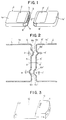
- reference numeral 1 generally designates a portable computer as the portable electronic apparatus of the present invention
- reference numeral 1' generally designates another portable computer having the same construction as that of the portable computer 1.
- the portable computer 1' constitutes the external apparatus according to the present invention.
- Reference numeral 1a designates a casing of the portable computer 1
- reference numeral 1a' designates a casing of the portable computer 1'.
- the casings 1a and 1a' are formed in a substantially rectangular shape.
- An upper surface of the casing 1a is provided with an operating portion 2 for displaying a command or the like and instructing execution of operation.
- an upper surface of the casing 1a' is provided with an operating portion 2' identical With the operating portion 2.
- One of side surfaces of the casing 1a is provided with an optical signal transmitting terminal 3 and an optical signal receiving terminal 4.
- the transmitting terminal 3 and the receiving terminal 4 are necessarily spaced apart from each other as far as possible, so as to prevent mutual interference.
- an IC card inserting slot 5 is formed between the transmitting terminal 3 and the receiving terminal 4 on the one side surface of the casing 1a. Accordingly, a space between the transmitting terminal 3 and the receiving terminal 4 can be ensured by a width of the slot 5, thereby preventing the mutual interference.
- the slot 5 is arranged at a middle portion of the one side surface of the casing 1a, and the transmitting terminal 3 and the receiving terminal 4 are arranged on opposite sides of the slot 5. Accordingly, a positional relation among the transmitting terminal 3, the receiving terminal 4 and the slot 5 can be clearly recognized.
- one of side surfaces of the casing 1a' of the portable computer 1' is also provided with a transmitting terminal, a receiving terminal and a slot which are identical with the transmitting terminal 3, the receiving terminal 4 and the slot 5 of the portable computer 1, respectively, so that the transmitting terminal of the portable computer 1' is adapted to face the receiving terminal 3 of the portable computer 1, and the receiving terminal of the portable computer 1' is adapted to face the transmitting terminal of the portable computer 1.
- the transmitting terminal 3 and the receiving terminal 4 are arranged in symmetrical relationship to each other with respect to a longitudinal central point on the one side surface of the casing 1a. That is, assuming that a central point on a center line in respect of a longitudinal direction of the one side surface of the casing 1a is defined as a reference point, the transmitting terminal 3 and the receiving terminal 4 are arranged in equally spaced relationship from this reference point, i.e., in symmetrical relationship to this reference point. Further, a transparent cover 6 formed of resin or the like is provided on the one side surface of the casing 1a so as to cover the transmitting terminal 3 and the receiving terminal 4. The slot 5 is formed through the cover 6.
- the transmitting terminal 3, the receiving terminal 4 and the cover 6 constitute an essential part of the present invention, and this essential part is applied to a portable computer in the preferred embodiment shown in Fig. 1.
- the portable computer including this essential part, data is received as an optical signal from the receiving terminal 3, and data collected in the portable computer is transmitted as an optical signal to the outside.
- data transfer is carried out between the portable computers 1 and 1' of the same kind.
- the one side surface of the casing 1a of the portable computer 1 on which surface the transmitting terminal 3 and the receiving terminal 4 are provided is attached to the one side surface of the casing 1a' of the portable computer 1'.
- the reference point on the one side surface of the casing 1a becomes coincident with the reference point on the one side surface of the casing 1a'.
- the transmitting terminal 3 and the receiving terminal 4 on the one side surface of the casing 1a are arranged in symmetrical relationship to each other with respect to the reference point, the transmitting terminal 3 of the portable computer 1 faces the receiving terminal of the portable computer 1', and the receiving terminal 4 of the portable computer 1 faces the transmitting terminal of the portable computer 1'.
- the transmitting terminal 3 of the portable computer 1 faces the receiving terminal of the portable computer 1'
- the receiving terminal 4 of the portable computer 1 faces the transmitting terminal of the portable computer 1'.
- Fig. 2 shows a second preferred embodiment of the present invention, in which the same reference numerals as those shown in Fig. 1 designates like or corresponding parts.
- the transmitting terminal, the receiving terminal and the slot of the portable computer 1' are designated by reference numerals 3', 4' and 5', respectively.
- the second preferred embodiment differs from the first preferred embodiment in the point that the covers 6 and 6' are specially designed. That is, the cover 6 of the portable computer 1 is provided with a projection 6a at a portion corresponding to the transmitting terminal 3, and is also provided with a recess 6b at a portion corresponding to the receiving terminal 4.
- the cover 6' of the portable computer 1' is provided with a projection 6a' at a portion corresponding to the transmitting terminal 3', and is also provided with a recess 6b' at a portion corresponding to the receiving terminal 4'.
- the projection 6a of the cover 6 comes into engagement with the recess 6b' of the cover 6'
- the recess 6b of the cover 6 comes into engagement with the projection 6a' of the cover 6'. Therefore, the alignment of the optical paths can be effected more easily as compared with the first preferred embodiment shown in Fig. 1.
- the covers 6 and 6' also serve as guides.
- the projection 6a is formed at its top with a recess 6c in the range of light transmission.
- the projection 6a' is formed at its top with a recess 6c' in the range of light transmission.
- the transmitting terminal 3 and the receiving terminal 4 of the portable computer 1 can be closely aligned to the receiving terminal 4' and the transmitting terminal 3' of the portable computer 1', respectively, so that electrically non-contact optical space communication between both the portable computers 1 and 1' is effected. Accordingly, it is unnecessary to provide a connecting cable or a connector for data transfer.
- the transmitting terminal 3 and the receiving terminal 4 of the portable computer 1 are disposed close to the receiving terminal 4' and the transmitting terminal 3' of the portable computer 1', respectively. Accordingly, an output of the transmitting terminals 3 and 3' can be made smaller than that in the conventional optical space communication.
- optical space communication in the preferred embodiments is greatly effective as a method for data transfer between two portable electronic apparatuses of the same kind.
- the transmitting terminal 3 and the receiving terminal 4 of the portable computer 1 are disposed close to the receiving terminal 4' and the transmitting terminal 3, of the portable computer 1' in operation, an external noise is hardly mixed in.
- a sufficient receiving level can be ensured even though an output of an optical signal is low. Accordingly, in carrying out the data transfer by the optical space communication, no complex error correction is needed, and malfunction due to the external noise is hard to occur.
- Fig. 3 shows a third preferred embodiment of the present invention, in which data collected in the portable computer 1 is transferred to a peripheral apparatus 10 such as a printer.
- the peripheral apparatus 10 is provided with a connecting portion 11 for connecting the portable computer 1 and a mounting portion 12 for mounting the portable computer 1.
- the connecting portion 11 is provided with a transmitting terminal and a receiving terminal having the same function as that of the transmitting terminal 3 and the receiving terminal 4 of the portable computer 1.
- the connecting portion 11 is further provided with a recess adapted to engage the projection 6a of the portable computer 1 and a projection adapted to engage the recess 6b of the portable computer 1.
- Fig. 4 shows an electrical construction of the portable computer 1 in a schematic block diagram form.
- the portable computer 1 includes a control unit comprising a CPU 50 for generally controlling the operation, a ROM 51 previously storing a predetermined program, a RAM 52 for temporarily storing data, a clock generator 53 for generating an operation timing signal, and a gate array 55 for controlling the operating portion 2, the transmitting terminal 3 and the receiving terminal 4.
- the gate array 55 also controls a speaker 54 to output a predetermined sound signal thereto.
- Reference numeral 56 denotes an IC card to be inserted from the slot 5.
- the program stored in the ROM 51 is executed by the CPU 50 with a period of clock generated by the clock generator 53.
- Data received from the receiving terminal 4 is temporarily stored into the RAM 52, and if required, the data is stored into the IC card 56.
- a predetermined command is input by operating the operating portion 2, as required, and it is displayed on the operating portion. Further, a sound is generated from the speaker 54, if required.
- a transmitting timing of an optical signal from the transmitting terminal 3 and a receiving timing of an optical signal from the receiving terminal 4 are decided by the gate array 55.
Landscapes
- Engineering & Computer Science (AREA)
- Physics & Mathematics (AREA)
- Electromagnetism (AREA)
- Computer Networks & Wireless Communication (AREA)
- Signal Processing (AREA)
- Theoretical Computer Science (AREA)
- General Engineering & Computer Science (AREA)
- General Physics & Mathematics (AREA)
- Optical Communication System (AREA)
- Telephone Set Structure (AREA)
Applications Claiming Priority (2)
| Application Number | Priority Date | Filing Date | Title |
|---|---|---|---|
| JP298983/90 | 1990-11-06 | ||
| JP02298983A JP3114198B2 (ja) | 1990-11-06 | 1990-11-06 | 電子機器 |
Publications (3)
| Publication Number | Publication Date |
|---|---|
| EP0484912A2 true EP0484912A2 (de) | 1992-05-13 |
| EP0484912A3 EP0484912A3 (en) | 1993-02-10 |
| EP0484912B1 EP0484912B1 (de) | 1998-09-02 |
Family
ID=17866719
Family Applications (1)
| Application Number | Title | Priority Date | Filing Date |
|---|---|---|---|
| EP91118923A Expired - Lifetime EP0484912B1 (de) | 1990-11-06 | 1991-11-06 | Tragbares elektronisches Gerät |
Country Status (6)
| Country | Link |
|---|---|
| US (1) | US5210427A (de) |
| EP (1) | EP0484912B1 (de) |
| JP (1) | JP3114198B2 (de) |
| KR (1) | KR0179373B1 (de) |
| CA (1) | CA2054661C (de) |
| DE (1) | DE69130103T2 (de) |
Cited By (5)
| Publication number | Priority date | Publication date | Assignee | Title |
|---|---|---|---|---|
| DE29501275U1 (de) * | 1995-01-27 | 1995-03-23 | Siemens Ag | Sende-/Empfangsanordnung für Mobilfunk |
| DE19513952A1 (de) * | 1994-07-13 | 1996-01-18 | Olympus Optical Co | Sprachinformations-Übertragungssystem, das in der Lage ist, eine ein optisches Signal verwendende Sprachinformationsübertragung einfach durchzuführen |
| US5519527A (en) * | 1992-07-17 | 1996-05-21 | Milltronics Ltd. | Modem for communicating with enclosed electronic equipment |
| US5889602A (en) * | 1996-12-10 | 1999-03-30 | Motorola, Inc. | Optical hinge |
| US6055500A (en) * | 1994-07-13 | 2000-04-25 | Olympus Optical Co., Ltd. | Information transfer, recording and reproducing device |
Families Citing this family (8)
| Publication number | Priority date | Publication date | Assignee | Title |
|---|---|---|---|---|
| US5578834A (en) * | 1994-06-21 | 1996-11-26 | Tracker Technologies, Inc. | Electrical/optical interface coupler |
| WO1997002550A2 (en) * | 1995-07-05 | 1997-01-23 | Philips Electronics N.V. | System for communicating between a dynamic group of apparatuses |
| KR100195501B1 (ko) * | 1995-11-30 | 1999-06-15 | 김영남 | 레치형 전송기를 이용한 평판 표시기 데이타 구동 장치 |
| JP4962152B2 (ja) * | 2007-06-15 | 2012-06-27 | 日立電線株式会社 | 光電気複合伝送アセンブリ |
| US8829479B2 (en) * | 2008-11-21 | 2014-09-09 | L-3 Communications Corporation | Isolated high-speed digital interface for vehicles |
| JP2012093955A (ja) * | 2010-10-27 | 2012-05-17 | Kyocera Corp | 携帯型電子機器 |
| US20130329394A1 (en) * | 2011-02-07 | 2013-12-12 | Kyocera Corporation | Portable electronic device |
| DE102012009167A1 (de) * | 2012-05-08 | 2013-11-14 | NTTF Coatings GmbH | Verfahren und Vorrichtung zur Steuerung einer Außenbeleuchtungsanlage |
Citations (5)
| Publication number | Priority date | Publication date | Assignee | Title |
|---|---|---|---|---|
| FR2120342A5 (de) * | 1970-12-30 | 1972-08-18 | Mining Chemical Products | |
| JPS58200644A (ja) * | 1982-05-18 | 1983-11-22 | Fujitsu Ltd | 光バス方式 |
| JPS59169237A (ja) * | 1983-03-16 | 1984-09-25 | Nec Corp | 無接点接続方式 |
| JPS6358408A (ja) * | 1986-08-29 | 1988-03-14 | Matsushita Electric Ind Co Ltd | 光コネクタ接続装置 |
| US4856090A (en) * | 1984-05-22 | 1989-08-08 | Canon Kabushiki Kaisha | Light communication equipment |
Family Cites Families (6)
| Publication number | Priority date | Publication date | Assignee | Title |
|---|---|---|---|---|
| US4348740A (en) * | 1978-04-04 | 1982-09-07 | White Edward A | Method and portable apparatus for comparison of stored sets of data |
| DE3013705C2 (de) * | 1980-04-10 | 1985-10-10 | Siemens AG, 1000 Berlin und 8000 München | Anordnung zur Übertragung von Daten zwischen einem mobilen Datenerfassungsgerät und einem Datenverarbeitungsgerät |
| US4622681A (en) * | 1984-04-26 | 1986-11-11 | Empath Communications, Inc. | Apparatus for transmitting digital data |
| HU210122B (en) * | 1988-03-23 | 1995-02-28 | Biorex Kutato Fejlesztoe Kft | Process for production of composition against thromboembolytic conditions of circulating system and heart |
| HUT50044A (en) * | 1988-04-12 | 1989-12-28 | Bristol Myers Co | Process for producing pharmaceutical composition comprising megestrol acetate as active ingredient |
| JP2602715B2 (ja) * | 1988-04-12 | 1997-04-23 | 日本製紙 株式会社 | 抗ウィルス性医薬用組成物 |
-
1990
- 1990-11-06 JP JP02298983A patent/JP3114198B2/ja not_active Expired - Fee Related
-
1991
- 1991-10-31 CA CA002054661A patent/CA2054661C/en not_active Expired - Fee Related
- 1991-11-04 US US07/787,037 patent/US5210427A/en not_active Expired - Lifetime
- 1991-11-05 KR KR1019910019553A patent/KR0179373B1/ko not_active IP Right Cessation
- 1991-11-06 DE DE69130103T patent/DE69130103T2/de not_active Expired - Fee Related
- 1991-11-06 EP EP91118923A patent/EP0484912B1/de not_active Expired - Lifetime
Patent Citations (5)
| Publication number | Priority date | Publication date | Assignee | Title |
|---|---|---|---|---|
| FR2120342A5 (de) * | 1970-12-30 | 1972-08-18 | Mining Chemical Products | |
| JPS58200644A (ja) * | 1982-05-18 | 1983-11-22 | Fujitsu Ltd | 光バス方式 |
| JPS59169237A (ja) * | 1983-03-16 | 1984-09-25 | Nec Corp | 無接点接続方式 |
| US4856090A (en) * | 1984-05-22 | 1989-08-08 | Canon Kabushiki Kaisha | Light communication equipment |
| JPS6358408A (ja) * | 1986-08-29 | 1988-03-14 | Matsushita Electric Ind Co Ltd | 光コネクタ接続装置 |
Non-Patent Citations (4)
| Title |
|---|
| IBM TECHNICAL DISCLOSURE BULLETIN. vol. 25, no. 1, June 1982, NEW YORK US pages 269 - 270 D.D.LEAK 'Optical Signal Connection' * |
| PATENT ABSTRACTS OF JAPAN vol. 12, no. 278 (P-738)1 August 1988 & JP-A-63 058 408 ( MATSUSHITA ELECTRIC ) 14 March 1988 * |
| PATENT ABSTRACTS OF JAPAN vol. 8, no. 44 (E-229)(1481) 25 February 1984 & JP-A-58 200 644 ( FUJITSU ) * |
| PATENT ABSTRACTS OF JAPAN vol. 9, no. 23 (E-293)(1746) 3 January 1985 & JP-A-59 169 237 ( NIPPON DENKI ) 25 September 1984 * |
Cited By (5)
| Publication number | Priority date | Publication date | Assignee | Title |
|---|---|---|---|---|
| US5519527A (en) * | 1992-07-17 | 1996-05-21 | Milltronics Ltd. | Modem for communicating with enclosed electronic equipment |
| DE19513952A1 (de) * | 1994-07-13 | 1996-01-18 | Olympus Optical Co | Sprachinformations-Übertragungssystem, das in der Lage ist, eine ein optisches Signal verwendende Sprachinformationsübertragung einfach durchzuführen |
| US6055500A (en) * | 1994-07-13 | 2000-04-25 | Olympus Optical Co., Ltd. | Information transfer, recording and reproducing device |
| DE29501275U1 (de) * | 1995-01-27 | 1995-03-23 | Siemens Ag | Sende-/Empfangsanordnung für Mobilfunk |
| US5889602A (en) * | 1996-12-10 | 1999-03-30 | Motorola, Inc. | Optical hinge |
Also Published As
| Publication number | Publication date |
|---|---|
| DE69130103T2 (de) | 1999-01-21 |
| EP0484912B1 (de) | 1998-09-02 |
| EP0484912A3 (en) | 1993-02-10 |
| KR0179373B1 (ko) | 1999-05-15 |
| CA2054661A1 (en) | 1992-05-07 |
| JP3114198B2 (ja) | 2000-12-04 |
| JPH04172025A (ja) | 1992-06-19 |
| KR920010456A (ko) | 1992-06-26 |
| US5210427A (en) | 1993-05-11 |
| CA2054661C (en) | 2002-01-01 |
| DE69130103D1 (de) | 1998-10-08 |
Similar Documents
| Publication | Publication Date | Title |
|---|---|---|
| US5210427A (en) | Portable electronic apparatus with optical inter-module communication | |
| US7364436B2 (en) | Low height USB interface connecting device and a memory storage apparatus thereof | |
| US5966487A (en) | External pluggable high frequency data communication module | |
| PL174007B1 (pl) | Adapter do sprzęgania pierwszego i drugiego urządzenia elektronicznego | |
| EP0597373A1 (de) | Dateneingabe für ein Schlosssystem mit aktivem Schlüssel | |
| EP2944990B1 (de) | Optisches kabel und elektronische vorrichtung mit dem kabel | |
| US8430690B2 (en) | USB application device and method for assembling USB application device | |
| US20030081907A1 (en) | Device for blocking emitted light | |
| US6195054B1 (en) | IC card with antenna | |
| JPH07210644A (ja) | 光通信カードユニット | |
| CN211741638U (zh) | 一种光模块 | |
| JP6977079B2 (ja) | コネクタ付き装置、コネクタ及びケーブル | |
| JP2002269505A (ja) | Icカードリーダ或いはicカードリーダライタ | |
| JP2001023710A (ja) | コンピュータシステム及びそれに使用するコネクタ | |
| JPH11177505A (ja) | 赤外線通信方法及び装置 | |
| JPH04153896A (ja) | 非接触型icカード情報処理システム | |
| EP0840541A1 (de) | Videokarte | |
| KR20030049084A (ko) | 범용 직렬 버스 포트를 내장한 이동 통신 단말기 | |
| CN116995593A (zh) | 一种线缆走线固定器、板间信号连接机构及服务器 | |
| JPH06120636A (ja) | 基板間接続構造 | |
| KR100343167B1 (ko) | 휴대용정보단말기의외부접속장치 | |
| JPH1049268A (ja) | Pcカード増設方法及びその装置 | |
| JPH11331335A (ja) | ストラップおよび情報処理端末 | |
| JPH11250196A (ja) | Pcカード及び接続コネクタ | |
| KR100188417B1 (ko) | 인터페이싱 케이블 |
Legal Events
| Date | Code | Title | Description |
|---|---|---|---|
| PUAI | Public reference made under article 153(3) epc to a published international application that has entered the european phase |
Free format text: ORIGINAL CODE: 0009012 |
|
| AK | Designated contracting states |
Kind code of ref document: A2 Designated state(s): DE FR GB |
|
| PUAL | Search report despatched |
Free format text: ORIGINAL CODE: 0009013 |
|
| AK | Designated contracting states |
Kind code of ref document: A3 Designated state(s): DE FR GB |
|
| 17P | Request for examination filed |
Effective date: 19930712 |
|
| 17Q | First examination report despatched |
Effective date: 19951013 |
|
| GRAG | Despatch of communication of intention to grant |
Free format text: ORIGINAL CODE: EPIDOS AGRA |
|
| GRAG | Despatch of communication of intention to grant |
Free format text: ORIGINAL CODE: EPIDOS AGRA |
|
| GRAH | Despatch of communication of intention to grant a patent |
Free format text: ORIGINAL CODE: EPIDOS IGRA |
|
| GRAH | Despatch of communication of intention to grant a patent |
Free format text: ORIGINAL CODE: EPIDOS IGRA |
|
| GRAA | (expected) grant |
Free format text: ORIGINAL CODE: 0009210 |
|
| AK | Designated contracting states |
Kind code of ref document: B1 Designated state(s): DE FR GB |
|
| REF | Corresponds to: |
Ref document number: 69130103 Country of ref document: DE Date of ref document: 19981008 |
|
| ET | Fr: translation filed | ||
| PLBE | No opposition filed within time limit |
Free format text: ORIGINAL CODE: 0009261 |
|
| STAA | Information on the status of an ep patent application or granted ep patent |
Free format text: STATUS: NO OPPOSITION FILED WITHIN TIME LIMIT |
|
| 26N | No opposition filed | ||
| REG | Reference to a national code |
Ref country code: GB Ref legal event code: IF02 |
|
| PGFP | Annual fee paid to national office [announced via postgrant information from national office to epo] |
Ref country code: GB Payment date: 20041104 Year of fee payment: 14 Ref country code: DE Payment date: 20041104 Year of fee payment: 14 |
|
| PGFP | Annual fee paid to national office [announced via postgrant information from national office to epo] |
Ref country code: FR Payment date: 20041109 Year of fee payment: 14 |
|
| PG25 | Lapsed in a contracting state [announced via postgrant information from national office to epo] |
Ref country code: GB Free format text: LAPSE BECAUSE OF NON-PAYMENT OF DUE FEES Effective date: 20051106 |
|
| PG25 | Lapsed in a contracting state [announced via postgrant information from national office to epo] |
Ref country code: DE Free format text: LAPSE BECAUSE OF NON-PAYMENT OF DUE FEES Effective date: 20060601 |
|
| GBPC | Gb: european patent ceased through non-payment of renewal fee |
Effective date: 20051106 |
|
| PG25 | Lapsed in a contracting state [announced via postgrant information from national office to epo] |
Ref country code: FR Free format text: LAPSE BECAUSE OF NON-PAYMENT OF DUE FEES Effective date: 20060731 |
|
| REG | Reference to a national code |
Ref country code: FR Ref legal event code: ST Effective date: 20060731 |