EP0484741A1 - Gerüstknoten - Google Patents
Gerüstknoten Download PDFInfo
- Publication number
- EP0484741A1 EP0484741A1 EP91118062A EP91118062A EP0484741A1 EP 0484741 A1 EP0484741 A1 EP 0484741A1 EP 91118062 A EP91118062 A EP 91118062A EP 91118062 A EP91118062 A EP 91118062A EP 0484741 A1 EP0484741 A1 EP 0484741A1
- Authority
- EP
- European Patent Office
- Prior art keywords
- profile
- joining part
- scaffold
- node according
- pressing
- Prior art date
- Legal status (The legal status is an assumption and is not a legal conclusion. Google has not performed a legal analysis and makes no representation as to the accuracy of the status listed.)
- Granted
Links
- 238000003825 pressing Methods 0.000 claims abstract description 24
- 229910052782 aluminium Inorganic materials 0.000 claims abstract description 11
- XAGFODPZIPBFFR-UHFFFAOYSA-N aluminium Chemical compound [Al] XAGFODPZIPBFFR-UHFFFAOYSA-N 0.000 claims abstract description 11
- 230000006835 compression Effects 0.000 claims description 4
- 238000007906 compression Methods 0.000 claims description 4
- 238000005266 casting Methods 0.000 claims description 2
- 238000005242 forging Methods 0.000 claims description 2
- 239000004411 aluminium Substances 0.000 abstract 1
- 238000010276 construction Methods 0.000 description 2
- 238000006073 displacement reaction Methods 0.000 description 2
- 239000000463 material Substances 0.000 description 2
- 229910052751 metal Inorganic materials 0.000 description 2
- 239000002184 metal Substances 0.000 description 2
- 238000000034 method Methods 0.000 description 2
- 238000005452 bending Methods 0.000 description 1
- 230000006378 damage Effects 0.000 description 1
- 230000001419 dependent effect Effects 0.000 description 1
- 238000007373 indentation Methods 0.000 description 1
- 238000004519 manufacturing process Methods 0.000 description 1
- 238000009864 tensile test Methods 0.000 description 1
- 230000003313 weakening effect Effects 0.000 description 1
- 238000003466 welding Methods 0.000 description 1
Images

Classifications
-
- F—MECHANICAL ENGINEERING; LIGHTING; HEATING; WEAPONS; BLASTING
- F16—ENGINEERING ELEMENTS AND UNITS; GENERAL MEASURES FOR PRODUCING AND MAINTAINING EFFECTIVE FUNCTIONING OF MACHINES OR INSTALLATIONS; THERMAL INSULATION IN GENERAL
- F16B—DEVICES FOR FASTENING OR SECURING CONSTRUCTIONAL ELEMENTS OR MACHINE PARTS TOGETHER, e.g. NAILS, BOLTS, CIRCLIPS, CLAMPS, CLIPS OR WEDGES; JOINTS OR JOINTING
- F16B7/00—Connections of rods or tubes, e.g. of non-circular section, mutually, including resilient connections
-
- E—FIXED CONSTRUCTIONS
- E04—BUILDING
- E04G—SCAFFOLDING; FORMS; SHUTTERING; BUILDING IMPLEMENTS OR AIDS, OR THEIR USE; HANDLING BUILDING MATERIALS ON THE SITE; REPAIRING, BREAKING-UP OR OTHER WORK ON EXISTING BUILDINGS
- E04G7/00—Connections between parts of the scaffold
- E04G7/30—Scaffolding bars or members with non-detachably fixed coupling elements
- E04G7/302—Scaffolding bars or members with non-detachably fixed coupling elements for connecting crossing or intersecting bars or members
-
- F—MECHANICAL ENGINEERING; LIGHTING; HEATING; WEAPONS; BLASTING
- F16—ENGINEERING ELEMENTS AND UNITS; GENERAL MEASURES FOR PRODUCING AND MAINTAINING EFFECTIVE FUNCTIONING OF MACHINES OR INSTALLATIONS; THERMAL INSULATION IN GENERAL
- F16B—DEVICES FOR FASTENING OR SECURING CONSTRUCTIONAL ELEMENTS OR MACHINE PARTS TOGETHER, e.g. NAILS, BOLTS, CIRCLIPS, CLAMPS, CLIPS OR WEDGES; JOINTS OR JOINTING
- F16B17/00—Connecting constructional elements or machine parts by a part of or on one member entering a hole in the other and involving plastic deformation
- F16B17/004—Connecting constructional elements or machine parts by a part of or on one member entering a hole in the other and involving plastic deformation of rods or tubes mutually
Definitions
- the invention relates to a scaffold node, in particular for shelter frames made of aluminum, and a scaffold support for such a scaffold node.
- a joining part with profile head and joining part body is fixed in a non-detachable manner by pressing in a profiled rail which is congruent to the profile head, and a hollow profile enclosing the joining part body is also connected thereto by pressing.
- the parts to be joined are universal or freely configurable components for scaffold nodes that can be attached and designed as required. You can choose from an extruded profile, a hollow profile, and are therefore particularly inexpensive to produce because they do not require any pretreatment or aftertreatment.
- the parts to be joined can also be designed as castings or forgings, in particular when a cross section of the hollow tubes or hollow profiles to be connected which deviates from the rectangular cross section is necessary or desired.
- the jointed part body Since the connection between the jointed part body and the hollow profile is exposed to a tensile load in addition to the pressure load, which is largely absorbed by the contact surface between the jointed part body and the hollow profile, it is advantageous to provide the jointed part body with at least one rib, which is perpendicular to the longitudinal axis of the joint part and thus is arranged perpendicular to the axis of the hollow tube.
- the rib together with the pressing area, forms an additional positive connection to the frictional connection, which particularly reliably prevents the hollow profile from coming loose from the part to be joined.
- the ribs expediently run in the direction of the profile on the corresponding surfaces.
- circumferential ribs may be present.
- the internal dimensions of the hollow profile almost match the external dimensions of the part to be joined.
- the part to be joined and the hollow profile can be rectangular or circular, but other cross-sectional shapes can also be selected, if desired.
- the hollow profile is advantageously connected to the part to be joined by line compression, the pressing lines running between two ribs or at least in the direction of pull behind a rib.
- the press connection between the profile head of the joining part and the profile rail can take place either by deforming the profile rail or the strips which essentially form it in the profile direction in front of and behind the profile head in the form of press cams or dents. Another possibility is to create a point compression of the profile rail in the area of the profile head. Both measures can also be used at the same time.
- the invention further relates to a scaffold carrier or a profile for forming a scaffold equipped with the scaffold nodes according to the invention.
- This scaffold profile is characterized in that a plurality of profile rails are formed on it, so that joining parts pointing in different directions over the length can be arranged on this scaffold profile, to which appropriately aligned hollow tubes or hollow profiles are to be connected. This means that universally trained scaffolding can be created.
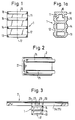
- a joining part 1 which consists of a profile head 11 and a joining part body 12.
- the part 12 to be joined is provided with a rib 15, which at the same time serves as a guide for the movement of the part 1 to be joined in a profile rail.
- ribs 13, 14 are provided, which are used for pressing with a hollow profile in a manner to be explained in more detail below. All the ribs 13, 14, 15 run perpendicular to the longitudinal axis 17 of the joining part 1.
- the profile head 11 is provided with projections 18, so that a T-profile 16 forms in its upper region, as is shown more clearly in FIG. 1a.
- Fig. 1a also makes it clear that the joining part 1 is preferably designed as an extruded hollow profile.
- a profile rail 2 correspondingly designed for the profile head 11 of the joining part 1 is shown in FIG essentially from a longitudinal strut 21 with two parallel guide strips 24, 25.
- the guide strips 24, 25 form an area which is congruent with the T-profile of the joining part.
- the joining part 1 can therefore be positively inserted with its profile head 11 into the profile rail 2 and pushed into the desired position. If this position is reached, for example as shown in Fig. 3, a press connection between the joining part 1 and profile rail 2 can be made.
- This pressing can be carried out fully automatically and mechanically.
- four press points 26, 27, 28, 29 are attached to the profile rail in the region of the guide bar 24; Corresponding pressing points are also located on the opposite guide bar 25.
- the cross-sectional area of the guide bars 24, 25 is not reduced by the pressing points which are arranged approximately regularly at intervals from one another, so that there is no material weakening.
- the pressing points 26, 27, 28, 29 secure the joining part 1 against displacements in the profile rail 2.
- pressing by pressing cams can also be carried out, as will be described in connection with FIG. 8.
- the profile head lying in the profile rail 2 is partially enclosed by the guide strips 24, 25, so that the connection can absorb a high tensile load in the direction of the longitudinal axis 17 of the joining part 1.
- a hollow profile 3 is pushed onto the combination of the joining part 1 and the profile rail 2 prepared in this way, as indicated in FIG. 4. Since the hollow profile 3 corresponds approximately in its internal dimensions to the external dimensions of the joining part body 12, it can be used against small Slide frictional resistance over the part 12 to be joined until it strikes the guide strips 24, 25.
- press connections are of course not detachable without destruction. If, however, it should be necessary to replace the hollow profile 3, it only has to be cut open in the longitudinal direction in the region of the joining part in order to then be able to pull it off. Even if the joining part were damaged in the process, which can happen in particular in the area of the ribs, these ribs will essentially remain functional, so that a new hollow profile can be put on and pressed.
- FIG. 6 shows a perspective view of the scaffold node.
- the profile head 11 of the joining part 1 is accommodated between the guide strips 24, 25 of the profile rail 2 and lies against the inside of the longitudinal strut 21.
- the hollow profile 3 is pushed to the guide strips 24, 25 with a precise fit on the joining part 1 and is pressed on its top and bottom with the joining part 1 along the pressing lines 31, 32, 33, 34.
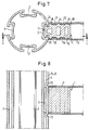
- FIG. 7 shows a scaffold girder in cross section, which has four profile strips 2 which can be used for scaffold nodes according to the present invention.
- an arrangement of the profile rails 2 is selected at an angular distance of 90 °, but the arrangement can be adapted according to the requirements, depending on the application.
- a joining part 1 is with its profile head 11 introduced into one of the profile rails 2, the dimensions of the joining part 1 and the profile rail 2 being chosen such that one of the ribs 15 on the joining part body 12 forms a stop for the guide strips 24, 25 of the profile rail 2.
- Press lines 31, 32 are attached between the ribs 14, 15, press lines 33, 34 between the ribs 13, 14 of the joining part 1.
- the joining part 1 is provided in the region of the rib 13 with a bevel 19 which facilitates the placement of the hollow profile 3.
- FIG. 8 shows in the sectional view along the line A-A from FIG. 7 the fixing of the joining part 1 in the profile rail 2 in the direction of its course.
- 11 press cams 22, 23 are mounted in the guide strips 24, 25 above and below the profile head, so that a stop for the joining part 1 is formed by indentation or material displacement in the inner region of the guide strip 2.
- the pressing is not carried out directly with the joining part 1, this is nevertheless held securely in the position once it has been determined.
Abstract
Description
- Die Erfindung betrifft einen Gerüstknoten, insbesondere für Unterstellungsgerüste aus Aluminium sowie einen Gerüstträger für einen derartigen Gerüstknoten.
- Der Gerüstbau ist ein erheblicher Kostenfaktor auf einer Baustelle. Es besteht daher das Erfordernis, noch belastbare Gerüste zu schaffen, die gleichzeitig aber auch wirtschaftlich herstellbar sein müssen.
- Um aus Gründen der einfachen Handhabbarkeit Baugerüste möglichst leicht zu gestalten, werden diese heute zunehmend aus Leichtmetall, insbesondere Aluminium, hergestellt. Bei Aluminium können aber Schweißverbindungen zwischen den Stützen bzw. Trägern der Gerüste nur bedingt eingesetzt werden, weil beim Schweißen von Aluminium eine Minderung der Festigkeit bis zu 50% eintritt. Diese müßte durch eine entsprechende Erhöhung des Querschnitts der Profile des Gerüsts kompensiert werden, was wieder zu einem Mehrgewicht sowie zu einer Kostenerhöhung führt. Darüber hinaus muß bei einer Schweißverbindung bei Aluminium eine Vorbehandlung, insbesondere ein Entfernen der Oxidschicht, durchgeführt werden, wodurch sich durch Schweißen hergestellte Aluminium-Verbindungen entsprechend verteuern.
- Bei nicht hochbelasteten Gerüsten, z.B. Arbeitsgerüsten, wird die Verbindung der Profile teilweise bereits durch Verpressen hergestellt. Dabei erfolgt das Verpressen von zwei ineinandergeschobenen Profilen von innen nach außen. Nachdem hierfür die Preßwerkzeuge in das Innenrohr eingeführt werden müssen, gestalten sich Werkzeug sowie Preßvorgang aufwendig. Eine Verpressung von außen nach innen erfolgt derzeit vorwiegend nur bei Rohr- bzw. Rahmenenden.
- Bei Aluminium-Konstruktionen werden die Knoten zwischen den Profilen auch durch Schraubverbindungen hergestellt. So ist in der VDI-Zeitschrift Bd. 129 (1987), S. 22, eine Traganordnung dargestellt, bei der die Verbindung zwischen Träger und Strebe mittels einer Schraubplatte als Ringverbinder erzielt ist. Auf Seite 29 derselben Ausgabe der Zeitschrift ist eine weitere Schraubversion gezeigt, bei der Träger und Strebe über Eckstöße miteinander verbunden werden. Da Aluminium ein mechanisch nicht sehr widerstandsfähiges Metall ist, werden allerdings in Aluminium geschnittene Gewinde sehr bald verschleißen. Daher wird in der "Fahrzeug + Karosserie", Ausgabe 1/1984, vorgeschlagen, Gewindeplättchen zu verwenden, die hinter die eigentliche Eckverbindung in einer T-Schiene am Träger und in der Strebe eingelegt werden und die mechanischen Kräfte beim Anziehen der Schrauben aufnehmen sollen. Diese Maßnahme führt natürlich zu einer Verteuerung der Verbindungsstelle.
- Es ist daher die Aufgabe der Erfindung, eine wirtschaftlich herstellbare Gerüstanordnung zu schaffen, die eine einfache und deshalb kostengünstige Verbindung zwischen den Profilen aufweist und sich trotzdem durch eine hohe Dauerlastfestigkeit auszeichnet.
- Diese Aufgabe wird durch einen Gerüstknoten für ein einschlägiges Gerüst mit den Merkmalen des Anspruchs 1 gelöst. Vorteilhafte Ausgestaltungen sind Gegenstand der Unteransprüche.
- Erfindungsgemäß ist ein Fügeteil mit Profilkopf und Fügeteilkörper in einer zum Profilkopf kongruent ausgebildeten Profilschiene durch Verpressen unlösbar festgelegt und ein den Fügeteilkörper umschließendes Hohlprofil mit diesem ebenfalls durch Verpressen verbunden. Die Fügeteile sind dabei universell bzw. beliebig ausbildbare Bauteile für beliebig anzubringende und auszugestaltende Gerüstknoten. Sie können aus einem Strangpreß-Profil, u.U. einem Hohlprofil, gebildet sein und sind daher insbesondere deswegen kostengünstig herstellbar, weil sie keiner Vor- oder Nachbehandlung bedürfen. Die Fügeteile können aber auch als Gußstücke bzw. Schmiedestücke ausgebildet sein, insbesondere dann, wenn ein vom Rechteckquerschnitt abweichender Querschnitt der zu verbindenden Hohlrohre bzw. Hohlprofile notwendig bzw. gewünscht ist.
- Durch das Verpressen des Profilkopfes in der entsprechend ausgebildeten Profilschiene wird eine definierte Verbindung geschaffen, die eine hohe Zug- und Biegefestigkeit aufweist, da längs des gesamten Verbindungsbereiches keine Festigkeitsminderung auftritt. Ein gleiches gilt für die Verbindungsstelle zwischen dem Fügeteilkörper und dem Hohlprofil.
- Da die Verbindung zwischen Fügeteilkörper und Hohlprofil neben der Druckbelastung, die weitgehend durch die Auflagefläche zwischen Fügeteilkörper und Hohlprofil aufgefangen wird, auch einer Zugbelastung ausgesetzt ist, ist es vorteilhaft, den Fügeteilkörper mit wenigstens einer Rippe zu versehen, die senkrecht zur Längsachse des Fügeteils und damit senkrecht zur Achse des Hohlrohres verlaufend angeordnet ist. Die Rippe bildet zusammen mit dem Verpreßbereich einen zum Kraftschluß zusätzlichen Formschluß, der ein Lösen des Hohlprofils vom Fügeteilkörper besonders zuverlässig verhindert.
- Bei der Herstellung des Fügeteils als Strangpreß-Profil verlaufen zweckmäßigerweise die Rippen in die Richtung des Profils an den entsprechenden Flächen. Bei der Ausbildung des Fügeteils als Guß- bzw. Schmiedeteil können umlaufende Rippen vorhanden sein.
- Um eine verkippsichere Lage des Profilkopfes des Fügeteils in der Profilschiene sicherzustellen, empfiehlt es sich, den Profilkopf des Fügeteils T-förmig auszubilden. Dieses hat weiterhin den Vorteil, daß das Fügeteil längs der Profilschiene leicht in die gewünschte Lage verschiebbar ist.
- Verschiedenste Ausbildungen von Fügeteilkörper und Hohlprofil sind denkbar. Aus Zweckmäßigkeitsgründen stimmen die Innenabmessungen des Hohlprofiles nahezu mit den Außenabmessungen des Fügeteilkörpers überein. Im Querschnitt können, abhängig von der Herstellungsart, Fügeteilkörper und Hohlprofil rechteckig oder kreisförmig sein, es können aber auch andere Querschnittsformen, falls erwünscht, gewählt werden.
- Vorteilhaft ist das Hohlprofil mit dem Fügeteilkörper durch Linienverpressung verbunden, wobei die Preßlinien zwischen zwei Rippen oder aber zumindest in Zugrichtung hinter einer Rippe verlaufen.
- Die Preßverbindung zwischen dem Profilkopf des Fügeteils und der Profilschiene kann entweder durch Verformung der Profilschiene bzw. der sie im wesentlichen bildenden Leisten in Profilrichtung vor und hinter dem Profilkopf in Form von Preßnocken bzw. Einbeulungen erfolgen. Eine andere Möglichkeit ist darin zu sehen, eine Punktverpressung der Profilschiene im Bereich des Profilkopfes zu erzeugen. Es können auch beide Maßnahmen zugleich angewandt werden.
- Die Erfindung betrifft ferner einen Gerüstträger bzw. ein Profil zum Ausbilden eines mit den erfindungsgemäßen Gerüstknoten ausgestatteten Gerüsts. Dieses Gerüstprofil ist dadurch gekennzeichnet, daß an ihm eine Mehrzahl von Profilschienen ausgebildet sind, so daß an diesem Gerüstprofil über die Länge in unterschiedliche Richtung weisende Fügeteile angeordnet werden können, an die entsprechend ausgerichtete Hohlrohre bzw. Hohlprofile anzuschließen sind. Damit können universell ausgebildete Gerüste erstellt werden.
- Im folgenden soll die Erfindung lediglich beispielhaft anhand der beigefügten Zeichnungen erläutert werden. Es zeigt:
- Fig. 1
- eine schematische Darstellung eines Fügeteils für einen erfindungsgemäßen Gerüstknoten,
- Fig. 1a
- einen Längsschnitt des Fügeteils aus Fig. 1,
- Fig. 2
- eine schematische Darstellung einer Profilleiste,
- Fig. 3
- eine schematische Darstellung des in der Profilleiste festgelegten Fügeteiles,
- Fig. 4
- eine Darstellung des Aufbringens eines Hohlprofiles zum Bilden eines Gerüstknotens,
- Fig. 5
- einen erfindungsgemäßen Gerüstknoten,
- Fig. 6
- eine perspektivische Ansicht des erfindungsgemäßen Gerüstknotens,
- Fig. 7
- die Querschnittsansicht eines Gerüstträgers mit einem erfindungsgemäßen Gerüstknoten, und
- Fig. 8
- eine Schnittansicht längs der Linie A-A aus Fig. 7.
- Fig. 1 zeigt ein Fügeteil 1, das aus einem Profilkopf 11 und einem Fügeteilkörper 12 besteht. Der Fügeteilkörper 12 ist mit einer Rippe 15 versehen, die gleichzeitig als Führung für die Bewegung des Fügeteils 1 in einer Profilschiene dient. Weiterhin sind Rippen 13, 14 vorgesehen, die in noch näher zu erläuternder Weise der Verpressung mit einem Hohlprofil dienen. Sämtliche Rippen 13, 14, 15 verlaufen senkrecht zur Längsachse 17 des Fügeteils 1. Der Profilkopf 11 ist mit Vorsprüngen 18 versehen, so daß sich in seinem oberen Bereich, wie in Fig. 1a deutlicher gezeigt, ein T-Profil 16 bildet. Die Fig. 1a macht ferner deutlich, daß der Fügeteil 1 bevorzugt als Strangpreß-Hohlprofil ausgebildet ist.
- Eine zum Profilkopf 11 des Fügeteils 1 entsprechend ausgebildete Profilschiene 2 zeigt Fig. 2. Sie besteht im wesentlichen aus einer Längsstrebe 21 mit zwei parallel verlaufenden Führungsleisten 24, 25. Die Führungsleisten 24, 25 bilden einen Bereich, der dem T-Profil des Fügeteils kongruent ist.
- Das Fügeteil 1 kann daher mit seinem Profilkopf 11 in die Profilschiene 2 formschlüssig eingeführt und bis in die gewünschte Position geschoben werden. Ist diese Position erreicht, beispielsweise wie in Fig. 3 dargestellt, kann eine Preßverbindung zwischen Fügeteil 1 und Profilschiene 2 vorgenommen werden. Diese Verpressung kann vollautomatisch und maschinell durchgeführt werden. Bei der in Fig. 3 dargestellten Preßverbindung sind vier Preßpunkte 26, 27, 28, 29 auf der Profilschiene im Bereich der Führungsleiste 24 angebracht; entsprechende Preßpunkte befinden sich ebenso auf der gegenüberliegenden Führungsleiste 25. Durch die in etwa regelmäßig in Abständen voneinander angebrachten Preßpunkte wird die Querschnittsfläche der Führungsleisten 24, 25 nicht verringert, so daß sich keine Materialschwächung ergibt. Die Preßpunkte 26, 27, 28, 29 sichern das Fügeteil 1 gegen Verschiebungen in der Profilschiene 2. Es kann aber auch eine Verpressung durch Preßnocken vorgenommen werden, wie dies in Zusammenhang mit Fig. 8 noch geschildert werden wird. Der in der Profilschiene 2 liegende Profilkopf wird teilweise von den Führungsleisten 24, 25 umschlossen, so daß die Verbindung eine hohe Zugbelastung in Richtung der Längsachse 17 des Fügeteils 1 aufnehmen kann.
- Auf die so vorbereitete Kombination von Fügeteil 1 und Profilschiene 2 wird, wie in Fig. 4 angedeutet, ein Hohlprofil 3 aufgeschoben. Da das Hohlprofil 3 in seinen Innenabmessungen etwa den Außenabmessungen des Fügeteilkörpers 12 entspricht, kann es gegen geringen Reibungswiderstand über den Fügeteilkörper 12 gleiten, bis es an die Führungsleisten 24, 25 anschlägt.
- Anschließend werden zwischen den Rippen des Fügeteilkörpers Linienverpressungen 31, 32, 33, 34 an dem Hohlprofil 3 angebracht. Damit ist der erfindungsgemäße Gerüstknoten fertiggestellt.
- Die Preßverbindungen sind natürlich nicht zerstörungsfrei lösbar. Falls es aber erforderlich sein sollte, das Hohlprofil 3 auszutauschen, muß dieses lediglich in Längsrichtung im Bereich des Fügeteils aufgeschnitten werden, um es sodann abziehen zu können. Selbst wenn das Fügeteil dabei beschädigt würde, was insbesondere im Bereich der Rippen geschehen kann, werden diese Rippen doch ihre Funktion im wesentlichen beibehalten, so daß ein neues Hohlprofil aufgesetzt und verpreßt werden kann.
- Fig. 6 zeigt eine perspektivische Ansicht des Gerüstknotens. Der Profilkopf 11 des Fügeteils 1 ist zwischen den Führungsleisten 24, 25 der Profilschiene 2 untergebracht und liegt an der Innenseite der Längsstrebe 21 an. Das Hohlprofil 3 ist paßgenau bis an die Führungsleisten 24, 25 auf das Fügeteil 1 geschoben und an seiner Ober- und Unterseite mit dem Fügeteil 1 längs der Preßlinien 31, 32, 33, 34 verpreßt.
- Fig. 7 zeigt einen Gerüstträger im Querschnitt, der vier Profilleisten 2 aufweist, die für Gerüstknoten gemäß der vorliegenden Erfindung verwendet werden können. Bei diesem Ausführungsbeispiel ist eine Anordnung der Profilschienen 2 im winkelmäßigen Abstand von 90° gewählt, jedoch kann die Anordnung gemäß den Erfordernissen, je nach Einsatzzweck, angepaßt werden. Ein Fügeteil 1 ist mit seinem Profilkopf 11 in eine der Profilschienen 2 eingebracht, wobei die Abmessungen von Fügeteil 1 und Profilschiene 2 so gewählt sind, daß eine der Rippen 15 am Fügeteilkörper 12 einen Anschlag für die Führungsleisten 24, 25 der Profilschiene 2 bilden. Preßlinien 31, 32 sind zwischen den Rippen 14, 15, Preßlinien 33, 34 zwischen den Rippen 13, 14 des Fügeteils 1 angebracht. Das Fügeteil 1 ist im Bereich der Rippe 13 mit einer Abschrägung 19 versehen, die das Aufsetzen des Hohlprofiles 3 erleichtert.
- Fig. 8 zeigt in der Schnittansicht längs der Linie A-A aus Fig. 7 das Festlegen des Fügeteils 1 in der Profilschiene 2 in deren Verlaufsrichtung. Danach sind oberhalb und unterhalb des Profilkopfes 11 Preßnocken 22, 23 in den Führungsleisten 24, 25 angebracht, so daß durch Einbuchtung bzw. Materialverdrängung in den Innenbereich der Führungsleiste 2 jeweils ein Anschlag für das Fügeteil 1 gebildet wird. Obwohl also die Verpressung nicht direkt mit dem Fügeteil 1 erfolgt, wird dieses doch sicher in der einmal festgelegten Position gehalten.
- Belastungsversuche, die im Vergleich zwischen geschweißten Knoten und erfindungsgemäßen Gerüstknoten durchgeführt worden sind, haben gezeigt, daß im Zugversuch die Haltbarkeit beim erfindungsgemäßen Gerüstknoten um etwa 50% höher liegt als bei der geschweißten Verbindung.
Claims (10)
- Gerüstknoten, insbesondere für Unterstellungsgerüste aus Aluminium, dadurch gekennzeichnet, daß ein Fügeteil (1) mit Profilkopf (11) und Fügeteilkörper (12) in einer zum Profilkopf (11) kongruent ausgebildeten Profilschiene (2) durch Verpressen festgelegt und ein den Fügeteilkörper (12) umschließendes Hohlprofil (3) mit diesem ebenfalls durch Verpressen verbunden ist.
- Gerüstknoten nach Anspruch 1, dadurch gekennzeichnet, daß der Fügeteilkörper (12) mit wenigstens einer Rippe (13, 14, 15) versehen ist, die senkrecht zur Längsachse (17) des Fügeteils (1) und damit senkrecht zur Achse des Hohlprofils (3) verlaufend angeordnet ist.
- Gerüstknoten nach Anspruch 1 oder 2, dadurch gekennzeichnet, daß der Profilkopf (11) des Fügeteils (1) T-förmig ausgebildet ist.
- Gerüstknoten nach einem der Ansprüche 1 bis 3, dadurch gekennzeichnet, daß der Fügeteilkörper (12) und das Hohlprofil (3) im Querschnitt im wesentlichen rechteckig sind, wobei die Innenabmessungen des Hohlprofiles (3) nahezu mit den Außenabmessungen des Fügeteilkörpers (12) übereinstimmen.
- Gerüstknoten nach einem der Ansprüche 1 bis 4, dadurch gekennzeichnet, daß der Fügeteil (1) als Strangpreß-Profil ausgebildet ist.
- Gerüstknoten nach einem der Ansprüche 1 bis 3, dadurch gekennzeichnet, daß der Fügeteilkörper (12) und das Hohlprofil (3) im Querschnitt im wesentlichen beliebig sind, wobei die Innenabmessungen des Hohlprofiles (3) nahezu mit den Außenabmessungen des Fügeteilkörpers (12) übereinstimmen und daß der Fügeteil (1) als Guß- oder Schmiedestück hergestellt ist.
- Gerüstknoten nach einem der Ansprüche 1 bis 6, dadurch gekennzeichnet, daß das Hohlprofil (3) mit dem Fügeteilkörper (12) durch Linienverpressung verbunden ist.
- Gerüstknoten nach einem der Ansprüche 1 bis 7, dadurch gekennzeichnet, daß der Profilkopf (11) des Fügeteils (1) in der Profilschiene (2) durch Verformungen der Profilschiene (2) beidseits des Profilkopfes (11) und/oder durch Punktverpressung im Bereich des Profilkopfes (11) festgelegt ist.
- Gerüstknoten nach Anspruch 8, dadurch gekennzeichnet, daß die Verformungen und/oder die Preßpunkte (26, 27, 28, 29) entlang von Führungsleisten (24, 25) der Profilschiene (2) angebracht sind.
- Gerüstträger für einen Gerüstknoten nach einem der Ansprüche 1 bis 9, dadurch gekennzeichnet, daß eine Vielzahl von Profilschienen (2) in dem Gerüstträger ausgebildet ist.
Applications Claiming Priority (2)
| Application Number | Priority Date | Filing Date | Title |
|---|---|---|---|
| DE9015416U | 1990-11-09 | ||
| DE9015416U DE9015416U1 (de) | 1990-11-09 | 1990-11-09 |
Publications (2)
| Publication Number | Publication Date |
|---|---|
| EP0484741A1 true EP0484741A1 (de) | 1992-05-13 |
| EP0484741B1 EP0484741B1 (de) | 1995-01-18 |
Family
ID=6859219
Family Applications (1)
| Application Number | Title | Priority Date | Filing Date |
|---|---|---|---|
| EP91118062A Expired - Lifetime EP0484741B1 (de) | 1990-11-09 | 1991-10-23 | Gerüstknoten |
Country Status (5)
| Country | Link |
|---|---|
| EP (1) | EP0484741B1 (de) |
| AT (1) | ATE117395T1 (de) |
| DE (2) | DE9015416U1 (de) |
| DK (1) | DK0484741T3 (de) |
| ES (1) | ES2067119T3 (de) |
Cited By (6)
| Publication number | Priority date | Publication date | Assignee | Title |
|---|---|---|---|---|
| US5762441A (en) * | 1996-05-17 | 1998-06-09 | Safway Steel Products, Inc. | End cap system for scaffolding planks |
| WO2005061812A1 (en) * | 2003-12-18 | 2005-07-07 | Alprogetti Srl | Bracket connecting a cross-piece and an upright and relative method of assembly |
| DE102006010447A1 (de) * | 2006-03-03 | 2007-09-06 | Alfer Aluminium Gesellschaft Mbh | Multifunktionsbausatz für Aufbewahrungszwecke |
| DE102007030925A1 (de) * | 2007-07-03 | 2009-01-08 | Alfer-Aluminium Gesellschaft Mbh | Hakenträgersystem |
| DE102020111133A1 (de) | 2020-04-23 | 2021-10-28 | Bayerische Motoren Werke Aktiengesellschaft | Profilstrebe, insbesondere für ein Kraftfahrzeug |
| DE102020111134A1 (de) | 2020-04-23 | 2021-10-28 | Bayerische Motoren Werke Aktiengesellschaft | Profilstrebe, insbesondere für ein Kraftfahrzeug |
Families Citing this family (3)
| Publication number | Priority date | Publication date | Assignee | Title |
|---|---|---|---|---|
| DE19859365A1 (de) * | 1998-12-22 | 2000-06-29 | Plettac Ag Geschaeftsbereich G | Gerüstrohr mit Eindrückungen zur Erhöhung der Lastaufnahmefähigkeit |
| DE102010021623A1 (de) | 2010-05-26 | 2011-12-01 | Johannes Weiss | Modulgerüst mit biegesteif anliegenden Rohrriegelanschlüssen |
| CN104863945A (zh) * | 2015-04-13 | 2015-08-26 | 苏州顺革智能科技有限公司 | 一种连接接头 |
Citations (4)
| Publication number | Priority date | Publication date | Assignee | Title |
|---|---|---|---|---|
| US1797691A (en) * | 1929-01-30 | 1931-03-24 | Merrill Whitney | Means for connecting tubular articles |
| US3778175A (en) * | 1971-06-04 | 1973-12-11 | E Zimmer | Snap locking structural joint assembly |
| DE2531263A1 (de) * | 1975-07-12 | 1977-01-27 | Tscherwitschke Gmbh Richard | Verfahren zum gegenseitigen verbinden von ineinander zu steckenden teilen und nach diesem verfahren hergestellte vorrichtung |
| EP0158149A1 (de) * | 1984-03-17 | 1985-10-16 | Jachmann, Ursula | Knotenpunktverbindung für lösbar miteinander verbindbare zylinderförmige Stäbe |
Family Cites Families (9)
| Publication number | Priority date | Publication date | Assignee | Title |
|---|---|---|---|---|
| AT282258B (de) * | 1968-02-08 | 1970-06-25 | Wizemann & Co J | Stößelstange |
| US3536345A (en) * | 1968-07-26 | 1970-10-27 | Bostwick Steel Lath Co The | Track for steel stud partitions |
| DE1935281A1 (de) * | 1969-07-11 | 1971-01-14 | Metallwerk Karl Leibfried Gmbh | Schnellwechselvorrichtung zum Ersetzen von Vorratsrollen in einer Abwickeleinrichtung zum Abwickeln von Materialbahnen |
| DE2222337A1 (de) * | 1972-05-06 | 1973-11-22 | Rainer Wolfram Wagner | Modellbau-profile, riegel und platten |
| GB2065820B (en) * | 1979-11-26 | 1983-07-20 | Design Research Marketing Pty | Nodal joint for space frames |
| FR2539827A1 (fr) * | 1983-01-20 | 1984-07-27 | Gueguen Sylvie | Noeud d'assemblage pour structures demontables, en particulier pour mobilier |
| DE3447036A1 (de) * | 1984-12-22 | 1986-07-10 | Audi AG, 8070 Ingolstadt | Formschluessige verbindung zwischen einem profilstab und einem knotenelement |
| DE8534237U1 (de) * | 1985-12-05 | 1986-01-23 | SCHÜCO Heinz Schürmann GmbH & Co, 4800 Bielefeld | Metallprofil zur Herstellung eines wärmegedämmten Verbundprofils |
| JPH0736925B2 (ja) * | 1988-07-14 | 1995-04-26 | 川崎重工業株式会社 | 複層結合棒状体及びその製造方法 |
-
1990
- 1990-11-09 DE DE9015416U patent/DE9015416U1/de not_active Expired - Lifetime
-
1991
- 1991-10-23 DE DE59104318T patent/DE59104318D1/de not_active Expired - Fee Related
- 1991-10-23 ES ES91118062T patent/ES2067119T3/es not_active Expired - Lifetime
- 1991-10-23 EP EP91118062A patent/EP0484741B1/de not_active Expired - Lifetime
- 1991-10-23 DK DK91118062.8T patent/DK0484741T3/da active
- 1991-10-23 AT AT91118062T patent/ATE117395T1/de not_active IP Right Cessation
Patent Citations (4)
| Publication number | Priority date | Publication date | Assignee | Title |
|---|---|---|---|---|
| US1797691A (en) * | 1929-01-30 | 1931-03-24 | Merrill Whitney | Means for connecting tubular articles |
| US3778175A (en) * | 1971-06-04 | 1973-12-11 | E Zimmer | Snap locking structural joint assembly |
| DE2531263A1 (de) * | 1975-07-12 | 1977-01-27 | Tscherwitschke Gmbh Richard | Verfahren zum gegenseitigen verbinden von ineinander zu steckenden teilen und nach diesem verfahren hergestellte vorrichtung |
| EP0158149A1 (de) * | 1984-03-17 | 1985-10-16 | Jachmann, Ursula | Knotenpunktverbindung für lösbar miteinander verbindbare zylinderförmige Stäbe |
Cited By (9)
| Publication number | Priority date | Publication date | Assignee | Title |
|---|---|---|---|---|
| US5762441A (en) * | 1996-05-17 | 1998-06-09 | Safway Steel Products, Inc. | End cap system for scaffolding planks |
| US6076991A (en) * | 1996-05-17 | 2000-06-20 | Safway Steel Products, Inc. | End cap system for scaffolding planks |
| WO2005061812A1 (en) * | 2003-12-18 | 2005-07-07 | Alprogetti Srl | Bracket connecting a cross-piece and an upright and relative method of assembly |
| DE102006010447A1 (de) * | 2006-03-03 | 2007-09-06 | Alfer Aluminium Gesellschaft Mbh | Multifunktionsbausatz für Aufbewahrungszwecke |
| DE102006010447B4 (de) | 2006-03-03 | 2019-06-27 | Alfer Aluminium Gesellschaft Mbh | Multifunktionsbausatz zum Montieren von Aufbewahrungsvorrichtungen |
| DE102007030925A1 (de) * | 2007-07-03 | 2009-01-08 | Alfer-Aluminium Gesellschaft Mbh | Hakenträgersystem |
| DE102007030925B4 (de) * | 2007-07-03 | 2020-03-12 | Alfer-Aluminium Gesellschaft Mbh | Hakenträgersystem |
| DE102020111133A1 (de) | 2020-04-23 | 2021-10-28 | Bayerische Motoren Werke Aktiengesellschaft | Profilstrebe, insbesondere für ein Kraftfahrzeug |
| DE102020111134A1 (de) | 2020-04-23 | 2021-10-28 | Bayerische Motoren Werke Aktiengesellschaft | Profilstrebe, insbesondere für ein Kraftfahrzeug |
Also Published As
| Publication number | Publication date |
|---|---|
| DE9015416U1 (de) | 1991-01-24 |
| DK0484741T3 (da) | 1995-04-10 |
| ATE117395T1 (de) | 1995-02-15 |
| EP0484741B1 (de) | 1995-01-18 |
| ES2067119T3 (es) | 1995-03-16 |
| DE59104318D1 (de) | 1995-03-02 |
Similar Documents
| Publication | Publication Date | Title |
|---|---|---|
| EP0452256B1 (de) | Eckverbindung zweier Profile mit C-förmigem Anschluss mittels eines Eckverbinders und Winkelstück zur Herstellung der Verbindung | |
| DE2508592C3 (de) | Konsole zum Anschluß eines Trägers an eine Stütze in Stahlskelett-Hochbauten | |
| EP0484741B1 (de) | Gerüstknoten | |
| DE2526660C3 (de) | Gebäudekonstruktion mit einem Raumfachwerk aus Stäben und Knotenstücken und einer Außenhaut | |
| EP0335150A2 (de) | Eckverbinder für Sandwichplatten von Wohnwagenaufbauten | |
| DE2206973A1 (de) | Raeumliches bauelement zur bildung von trag- und stuetzwerken aller art | |
| EP1769160B1 (de) | Adapter zum anschluss von bauelementen untereinander und bauteil hergestellt unter verwendung eines solchen adapters | |
| EP3728757B1 (de) | Verfahren zum herstellen eines profilverbunds mit speziellen verbindungselementen | |
| AT501334B1 (de) | Rahmenkonstruktion | |
| DE202008007467U1 (de) | Abstützvorrichtung, insbesondere Unterstellbock | |
| DE844055C (de) | Stabfoermiges Bauelement, insbesondere fuer voruebergehend benutzte Gerueste oder Vorrichtungen | |
| DE102010008668A1 (de) | Verbindungssystem und Verfahren zum Herstellen eines Verbindungssystems | |
| DE2940030C2 (de) | Knotenpunkt für lösbare biegesteife Eckverbindungen von Stäben | |
| DE1276315B (de) | Profiltraeger, insbesondere fuer Aufzugsgerueste, Seilbahnkabinen od. dgl. | |
| DE202016008379U1 (de) | Nachführbare Trägervorrichtung für Solarmodule mit Sparrenprofilschiene | |
| DE19741130C1 (de) | Lösbare Stoßverbindung für Rohre | |
| DE2145021C3 (de) | Dachbindereinheit für Winterbauhallen | |
| EP3249103B1 (de) | Stütze einer hochwasserschutzwand | |
| AT257901B (de) | Tafelförmiges Bauelement | |
| DE2535815A1 (de) | Konsole fuer stahlskelettbauten | |
| EP0805281A1 (de) | Verbindungsanordnung mit zwei stabförmigen Profilen | |
| CH598878A5 (en) | Bending machine for ribbed circular sections | |
| DE2113756A1 (de) | Verfahren zur Herstellung eines fachwerkaehnlichen Traegers | |
| DE19545453A1 (de) | Hubgerüst | |
| DE2614701C2 (de) | Flanschverbindung von Zuggabelholmen mit Längsträgern von Anhängern |
Legal Events
| Date | Code | Title | Description |
|---|---|---|---|
| PUAI | Public reference made under article 153(3) epc to a published international application that has entered the european phase |
Free format text: ORIGINAL CODE: 0009012 |
|
| AK | Designated contracting states |
Kind code of ref document: A1 Designated state(s): AT BE CH DE DK ES FR GB IT LI NL SE |
|
| 17P | Request for examination filed |
Effective date: 19920612 |
|
| 17Q | First examination report despatched |
Effective date: 19931006 |
|
| GRAA | (expected) grant |
Free format text: ORIGINAL CODE: 0009210 |
|
| ITF | It: translation for a ep patent filed |
Owner name: BARZANO' E ZANARDO MILANO S.P.A. |
|
| AK | Designated contracting states |
Kind code of ref document: B1 Designated state(s): AT BE CH DE DK ES FR GB IT LI NL SE |
|
| REF | Corresponds to: |
Ref document number: 117395 Country of ref document: AT Date of ref document: 19950215 Kind code of ref document: T |
|
| EAL | Se: european patent in force in sweden |
Ref document number: 91118062.8 |
|
| GBT | Gb: translation of ep patent filed (gb section 77(6)(a)/1977) |
Effective date: 19950123 |
|
| REF | Corresponds to: |
Ref document number: 59104318 Country of ref document: DE Date of ref document: 19950302 |
|
| REG | Reference to a national code |
Ref country code: ES Ref legal event code: FG2A Ref document number: 2067119 Country of ref document: ES Kind code of ref document: T3 |
|
| REG | Reference to a national code |
Ref country code: DK Ref legal event code: T3 |
|
| ET | Fr: translation filed | ||
| PLBE | No opposition filed within time limit |
Free format text: ORIGINAL CODE: 0009261 |
|
| STAA | Information on the status of an ep patent application or granted ep patent |
Free format text: STATUS: NO OPPOSITION FILED WITHIN TIME LIMIT |
|
| 26N | No opposition filed | ||
| REG | Reference to a national code |
Ref country code: GB Ref legal event code: IF02 |
|
| PGFP | Annual fee paid to national office [announced via postgrant information from national office to epo] |
Ref country code: DK Payment date: 20020916 Year of fee payment: 12 |
|
| PGFP | Annual fee paid to national office [announced via postgrant information from national office to epo] |
Ref country code: CH Payment date: 20021029 Year of fee payment: 12 |
|
| PGFP | Annual fee paid to national office [announced via postgrant information from national office to epo] |
Ref country code: NL Payment date: 20021031 Year of fee payment: 12 |
|
| PG25 | Lapsed in a contracting state [announced via postgrant information from national office to epo] |
Ref country code: CH Free format text: LAPSE BECAUSE OF NON-PAYMENT OF DUE FEES Effective date: 20031031 Ref country code: LI Free format text: LAPSE BECAUSE OF NON-PAYMENT OF DUE FEES Effective date: 20031031 |
|
| PG25 | Lapsed in a contracting state [announced via postgrant information from national office to epo] |
Ref country code: DK Free format text: LAPSE BECAUSE OF NON-PAYMENT OF DUE FEES Effective date: 20040430 |
|
| PG25 | Lapsed in a contracting state [announced via postgrant information from national office to epo] |
Ref country code: NL Free format text: LAPSE BECAUSE OF NON-PAYMENT OF DUE FEES Effective date: 20040501 |
|
| REG | Reference to a national code |
Ref country code: DK Ref legal event code: EBP |
|
| REG | Reference to a national code |
Ref country code: CH Ref legal event code: PL |
|
| NLV4 | Nl: lapsed or anulled due to non-payment of the annual fee |
Effective date: 20040501 |
|
| PGFP | Annual fee paid to national office [announced via postgrant information from national office to epo] |
Ref country code: ES Payment date: 20080825 Year of fee payment: 18 |
|
| PGFP | Annual fee paid to national office [announced via postgrant information from national office to epo] |
Ref country code: FR Payment date: 20080822 Year of fee payment: 18 Ref country code: IT Payment date: 20080916 Year of fee payment: 18 |
|
| PGFP | Annual fee paid to national office [announced via postgrant information from national office to epo] |
Ref country code: DE Payment date: 20081027 Year of fee payment: 18 |
|
| PGFP | Annual fee paid to national office [announced via postgrant information from national office to epo] |
Ref country code: AT Payment date: 20081031 Year of fee payment: 18 |
|
| PGFP | Annual fee paid to national office [announced via postgrant information from national office to epo] |
Ref country code: SE Payment date: 20081014 Year of fee payment: 18 Ref country code: BE Payment date: 20081029 Year of fee payment: 18 |
|
| PGFP | Annual fee paid to national office [announced via postgrant information from national office to epo] |
Ref country code: GB Payment date: 20081007 Year of fee payment: 18 |
|
| BERE | Be: lapsed |
Owner name: OSTERREICHISCHE *DOKA SCHALUNGSTECHNIK G.M.B.H. Effective date: 20091031 |
|
| EUG | Se: european patent has lapsed | ||
| REG | Reference to a national code |
Ref country code: FR Ref legal event code: ST Effective date: 20100630 |
|
| PG25 | Lapsed in a contracting state [announced via postgrant information from national office to epo] |
Ref country code: FR Free format text: LAPSE BECAUSE OF NON-PAYMENT OF DUE FEES Effective date: 20091102 Ref country code: DE Free format text: LAPSE BECAUSE OF NON-PAYMENT OF DUE FEES Effective date: 20100501 |
|
| PG25 | Lapsed in a contracting state [announced via postgrant information from national office to epo] |
Ref country code: AT Free format text: LAPSE BECAUSE OF NON-PAYMENT OF DUE FEES Effective date: 20091023 |
|
| PG25 | Lapsed in a contracting state [announced via postgrant information from national office to epo] |
Ref country code: BE Free format text: LAPSE BECAUSE OF NON-PAYMENT OF DUE FEES Effective date: 20091031 |
|
| PG25 | Lapsed in a contracting state [announced via postgrant information from national office to epo] |
Ref country code: GB Free format text: LAPSE BECAUSE OF NON-PAYMENT OF DUE FEES Effective date: 20091023 |
|
| REG | Reference to a national code |
Ref country code: ES Ref legal event code: FD2A Effective date: 20110303 |
|
| PG25 | Lapsed in a contracting state [announced via postgrant information from national office to epo] |
Ref country code: IT Free format text: LAPSE BECAUSE OF NON-PAYMENT OF DUE FEES Effective date: 20091023 |
|
| PG25 | Lapsed in a contracting state [announced via postgrant information from national office to epo] |
Ref country code: SE Free format text: LAPSE BECAUSE OF NON-PAYMENT OF DUE FEES Effective date: 20091024 |
|
| PG25 | Lapsed in a contracting state [announced via postgrant information from national office to epo] |
Ref country code: ES Free format text: LAPSE BECAUSE OF NON-PAYMENT OF DUE FEES Effective date: 20110302 |
|
| PG25 | Lapsed in a contracting state [announced via postgrant information from national office to epo] |
Ref country code: ES Free format text: LAPSE BECAUSE OF NON-PAYMENT OF DUE FEES Effective date: 20091024 |