EP0480117A1 - Auf- und Abseilgerät - Google Patents
Auf- und Abseilgerät Download PDFInfo
- Publication number
- EP0480117A1 EP0480117A1 EP90810778A EP90810778A EP0480117A1 EP 0480117 A1 EP0480117 A1 EP 0480117A1 EP 90810778 A EP90810778 A EP 90810778A EP 90810778 A EP90810778 A EP 90810778A EP 0480117 A1 EP0480117 A1 EP 0480117A1
- Authority
- EP
- European Patent Office
- Prior art keywords
- base plate
- roller
- lever
- rope
- abseiling
- Prior art date
- Legal status (The legal status is an assumption and is not a legal conclusion. Google has not performed a legal analysis and makes no representation as to the accuracy of the status listed.)
- Granted
Links
- 230000000903 blocking effect Effects 0.000 claims description 13
- 230000000694 effects Effects 0.000 description 3
- 241000282414 Homo sapiens Species 0.000 description 1
- 229910000831 Steel Inorganic materials 0.000 description 1
- 230000001133 acceleration Effects 0.000 description 1
- 230000001174 ascending effect Effects 0.000 description 1
- 238000007373 indentation Methods 0.000 description 1
- 210000000056 organ Anatomy 0.000 description 1
- 230000000717 retained effect Effects 0.000 description 1
- 239000010959 steel Substances 0.000 description 1
Images


Classifications
-
- B—PERFORMING OPERATIONS; TRANSPORTING
- B66—HOISTING; LIFTING; HAULING
- B66F—HOISTING, LIFTING, HAULING OR PUSHING, NOT OTHERWISE PROVIDED FOR, e.g. DEVICES WHICH APPLY A LIFTING OR PUSHING FORCE DIRECTLY TO THE SURFACE OF A LOAD
- B66F19/00—Hoisting, lifting, hauling or pushing, not otherwise provided for
-
- A—HUMAN NECESSITIES
- A62—LIFE-SAVING; FIRE-FIGHTING
- A62B—DEVICES, APPARATUS OR METHODS FOR LIFE-SAVING
- A62B1/00—Devices for lowering persons from buildings or the like
- A62B1/06—Devices for lowering persons from buildings or the like by making use of rope-lowering devices
Definitions
- the present invention relates to an up and abseil device, with a base plate on which a freely rotating abseiling roller with backstop, which contains a number of spring-loaded pinch rollers, is attached.
- a freely rotating abseiling roller with backstop which contains a number of spring-loaded pinch rollers.
- Such a device is commercially available and is recognized in some states as an official rescue device.
- the basic concept with the freely rotating pulley is based on an idea that was published in CH-A-526 308.
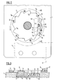
- Fig. 1 you can see the base plate 1, the abseiling roller 2 and the blocking device 3, which is integrated with the base plate and is protected from the weather.
- the abseiling roller 2 as it presents itself in FIG. 1, is known and is described in the aforementioned patent specification, with particular reference being made to the backstop with the clamping rollers, which lies between two life-lubricated ball bearings sealed on both sides.
- the abseiling roller turns freely when it is roped up and is fixed by the pinch rollers when it is abseiled.
- the rescue rope is wrapped around the abseiling roller two and a half times, which results in a braking effect and only a minimal holding force is required on the empty rope.
- the lateral, special cable guide is not shown, while the lower cable guide 4 is shown schematically because it is already known.
- the two openings 5 and 6 in the base plate 1 serve to fasten the abseiling device by means of a steel cable loop and other devices.
- the second backstop is recorded, which contains a ring gear 7 which is fastened on the side of the abseiling roller 2 facing the base plate 1, for example by means of Allen screws 8.
- the ring gear works together with a locking member 9 in such a way that the abseiling roller can turn freely in the direction of rotation indicated by the arrow and is locked in the opposite direction.
- the first backstop with the pinch rollers enables the same freewheel, respectively blocking the rotation of the abseiling roller.
- the locking member has a pin 10, around which a spring 11 is arranged, which is arranged in a longitudinal bore 12 in the base plate.
- the locking cam 13 of the locking member 9 runs in a slot 14 and protrudes beyond the base plate in order to be able to engage in the tooth spaces 7b of the toothed disk, while the wider body 15 of the locking member runs in a corresponding recess in the base plate.
- the teeth 7a push the locking member upward against the pressure of the spring 11 in FIG. 2 and in the opposite direction the spring presses the locking cam of the locking member downward into the locking position.
- the locking member 9 is closed by a disc 16 which is provided with a transparent window 17 in order to be able to control the position of the locking member from the outside.
- the blocking device 3 is accommodated in a housing, of which only the housing plate 18 is shown in FIG. 4, while the cover can be fastened in the bores 19 by means of screws.
- the housing plate has a shaped recess 20 in which the organs of the blocking device are accommodated.
- the blocking device contains a rotation about axis 21 bare pressure roller 22 which is connected to a lever 23.
- the pressure roller 22 has an inwardly curved outside in order to enclose the cable 24.
- the other end of the lever 23 is movably connected about the axis 25 to a clamping lever 26 which is mounted on the rigid axis 27. This clamping lever 26 also has a concave curvature on its front side 28 in order to receive the rope.
- a centrifugal force release 29 is provided to brake this movement.
- This trigger is located on the offset front part 30 of the pinch roller, the edge 31 of the offset part running through the center of the pinch roller, see Fig. 5.
- the centrifugal force trigger 29 consists of a release lever 32 which is mounted about the axis 33 and in rear third has a pin 34 to which one end of a tension spring 35 is attached, the other end of which is attached to the pinch roller.
- the spring 35 holds the release lever 32 in the retracted position.
- a pressure spring 36 acts via a pin 37 on the lever 23 and with it on the pressure roller 22 so that it is pressed against the rope and rotates when the rope slides downward. If either the other end of the rope is released or torn off, a strong acceleration of the rope downwards occurs at the indicated end of the rope in the blocking device and the centrifugal force trigger is thrown around and reaches the position of FIG. 5, with the free end of the release lever 32 behind the nose 38 arrives in the recess 20. As a result, the pressure roller is blocked on the one hand and, on the other hand, pressed against the rope, due to the lever action of the release lever.
- the lever 23 is activated, which in turn presses the clamping lever 26 in the direction of the rope, as a result of which a double clamping effect is achieved by the pressure roller and by the clamping lever.
- This causes the rope to be locked quickly and completely in the blocking device. Because the axis 27 of the clamping lever is supported in an indentation 39 of the recess 20, the effect of the clamping lever is retained even if the axis 27 should break.
Abstract
Description
- Die vorliegende Erfindung bezieht sich auf ein Auf- und Abseilgerät, mit einer Grundplatte, auf der eine freidrehend gelagerte Abseilrolle mit Rücklaufsperre, die eine Anzahl federbeaufschlagte Klemmrollen enthält, befestigt ist. Ein solches Gerät befindet sich im Handel und ist in einigen Staaten als offizielles Rettungsgerät anerkannt. Die Grundkonzeption mit der freidrehend gelagerten Seilrolle geht auf einen Gedanken zurück, der in der CH-A-526 308 veröffentlicht wurde.
- Um die Verwendung eines solchen Rettungsgerätes auf weitere Gebiete auszudehnen, ist es erforderlich, eine weitere Sicherung vorzusehen, und es ist daher Aufgabe der vorliegenden Erfindung, neben der Rücklaufsperre eine weitere Sicherung anzugeben. Diese erste Aufgabe wird mit dem in Patentanspruch 1 beschriebenen Gerät gelöst.
- Bei Absturzgefahr ist es bei vielen Arbeiten oder Rettungsaufgaben vorgeschrieben, eine weitere Absicherung vorzusehen, beispielsweise eine sogenannte "Tot-Mann-Sicherung", die als selbsttätige Blockiervorrichtung wirkt, falls der sichernden oder abseilenden Person das Seil entgleiten sollte. Es gehört daher zu dem vorbekannten und im Handel befindlichen Rettungsgerät ein Seilstopp-Handgriff, das auch in der vorgenannten Patentschrift offenbart ist. Es können Situationen entstehen, bei welchen dieser Seilstopp-Handgriff nicht vorhanden ist abgesehen davon, dass er ein zusätzliches loses Teil ist. Es ist davon ausgehend eine weitere Aufgabe der vorliegenden Erfindung, diese selbsttätige Blockiervorrichtung raumsparend und permanent mit dem Rettungsgerät zu vereinen. Diese Aufgabe wird mit dem Gerät gemäss den weiteren Ansprüchen gelöst.
- Die Erfindung wird im folgenden anhand einer Zeichnung eines Ausführungsbeispiels näher erläutert:
- Fig. 1 zeigt in perspektivischer Sicht das komplette erfindungsgemässe Auf-und Abseilgerät,
- Fig. 2 zeigt aufgeschnitten die zweite Rücklaufsperre des Gerätes,
- Fig. 3 zeigt einen Schnitt gemäss der Linie 111-111 in Fig. 2,
- Fig. 4 zeigt die integrierte selbsttätige Blokkiereinrichtung und
- Fig. 5 zeigt ein Detail dieser Blockiereinrichtung.
- In Fig. 1 erkennt man die Grundplatte 1, die Abseilrolle 2 sowie die Blockiereinrichtung 3, die mit der Grundplatte integriert und vor Witterungseinflüssen geschützt ist. Die Abseilrolle 2, wie sie sich in Fig. 1 präsentiert, ist bekannt und wird in der vorgenannten Patentschrift beschrieben, wobei insbesondere auf die Rücklaufsperre mit den Klemmrollen hingewiesen wird, die zwischen zwei Lebensdauer-geschmierten und beidseitig abgedichteten Kugellagern liegt. Beim Aufseilen dreht sich die Abseilrolle frei und beim Abseilen steht sie durch die Klemmrollen fest. Das Rettungsseil wird zweieinhalbmal um die Abseilrolle geschlungen, wodurch ein Bremseffekt erreicht wird und am Leerseil nur eine minimale Haltekraft notwendig ist. Nicht eingezeichnet ist die seitliche, spezielle Seilführung, während die untere Seilführung 4 schematisch, weil vorbekannt, eingezeichnet ist. Die beiden Oeffnungen 5 und 6 in der Grundplatte 1 dienen der Befestigung des Abseilgerätes mittels einer Stahlseilschlaufe sowie von weiteren Geräten.
- In den Fig. 2 und 3 ist die zweite Rücklaufsperre aufgezeichnet, die einen Zahnkranz 7 enthält, der auf der der Grundplatte 1 zugewandten Seite der Abseilrolle 2 befestigt ist, beispielsweise mittels Imbusschrauben 8. Der Zahnkranz arbeitet mit einem Sperrglied 9 zusammen derart, dass sich die Abseilrolle in der mit dem Pfeil angegebenen Drehrichtung frei drehen kann und in der Gegenrichtung gesperrt wird. Die erste Rücklaufsperre mit den Klemmrollen ermöglicht den gleichen Freilauf, respektive Sperrung der Drehung der Abseilrolle. In vorliegendem Ausführungsbeispiel weist das Sperrglied einen Stift 10 auf, um den eine Feder 11 angeordnet ist, die in einer Längsbohrung 12 in der Grundplatte angeordnet ist. Der Sperrnocken 13 des Sperrgliedes 9 läuft in einem Schlitz 14 und ragt über die Grundplatte hinaus, um in die Zahnlücken 7b der Zahnscheibe eingreifen zu können, während der breitere Körper 15 des Sperrgliedes in einer entsprechenden Ausnehmung in der Grundplatte läuft. Beim Drehen der Abseilrolle, respektive des Zahnkranzes in der mit dem Pfeil angegebenen Richtung stossen die Zähne 7a das Sperrglied entgegen dem Druck der Feder 11 in Fig. 2 nach oben und bei der Gegenrichtung drückt die Feder den Sperrnocken des Sperrgliedes nach unten in die Verriegelungsstellung. Das Sperrglied 9 wird durch eine Scheibe 16 verschlossen, die mit einem durchsichtigen Fenster 17 versehen ist, um die Stellung des Sperrgliedes von aussen kontrollieren zu können. Zu diesem Zwecke ist es von Vorteil, die Unterseite des Sperrgliedkörpers mit einer Markierung M zu versehen. Damit kann beim Drehen der Abseilrolle in der durch den Pfeil vorgegebenen Richtung festgestellt werden, ob das Sperrglied richtig funktioniert oder ob seine Abnutzung eine Auswechslung erfordert.
- Die Blockiereinrichtung 3 ist in einem Gehäuse untergebracht, wovon in Fig. 4 nur die Gehäuseplatte 18 eingezeichnet ist, während der Deckel mittels Schrauben in den Bohrungen 19 befestigt werden kann. Die Gehäuseplatte weist eine geformte Ausnehmung 20 auf, in welcher die Organe der Blockiereinrichtung untergebracht sind. Die Blockiereinrichtung enthält eine um Achse 21 drehbare Anpressrolle 22, die mit einem Hebel 23 verbunden ist. Die Anpressrolle 22 weist eine nach innen gewölbte Aussenseite auf, um das Seil 24 zu umfassen. Das andere Ende des Hebels 23 ist beweglich um Achse 25 mit einem Klemmhebel 26 verbunden, der an der starren Achse 27 gelagert ist. Dieser Klemmhebel 26 weist an seiner Vorderseite 28 ebenfalls eine konkave Wölbung auf, um das Seil aufzunehmen.
- In der in Fig. 4 eingezeichneten Stellung läuft das Seil nur sehr leicht gebremst an der Anpressrolle und am Klemmhebel vorbei. Falls nun die das Gerät benutzende Person das andere Seilende aus irgendeinem Grunde loslässt und somit das Seil in Abwärts- bzw. Pfeilrichtung beschleunigt wird, ist ein Fliehkraftauslöser 29 vorgesehen, diese Bewegung abzubremsen. Dieser Auslöser befindet sich auf dem abgesetzten vorderen Teil 30 der Klemmrolle, wobei die Kante 31 des abgesetzten Teils durch den Mittelpunkt der Klemmrolle verläuft, siehe Fig. 5. Der Fliehkraftauslöser 29 besteht aus einem Auslösehebel 32, der um die Achse 33 gelagert ist und im hinteren Drittel einen Stift 34 aufweist, an dem das eine Ende einer Zugfeder 35 befestigt ist, deren anderes Ende an der Klemmrolle befestigt ist. In der in Fig. 4 gezeigten Stellung hält die Feder 35 den Auslösehebel 32 in der eingezogenen Stellung. Ausserdem wirkt eine Anpressfeder 36 über einen Bolzen 37 auf den Hebel 23 und mit ihm auf die Anpressrolle 22, damit diese an das Seil angedrückt wird und beim Abwärtsgleiten des Seiles mitdreht. Wird nun entweder das andere Seilende losgelassen oder reisst dieses ab, entsteht am eingezeichneten Seilende bei der Blockiereinrichtung eine starke Beschleunigung des Seiles nach abwärts und dadurch wird der Fliehkraftauslöser herumgeschleudert und gelangt in die Stellung von Fig. 5, wobei das freie Ende des Auslösehebels 32 hinter die Nase 38 in der Ausnehmung 20 gelangt. Dadurch wird einerseits die Anpressrolle blockiert und andererseits gegen das Seil gepresst, dies infolge der Hebelwirkung des Auslösehebels. Ferner wird der Hebel 23 aktiviert, der seinerseits den Klemmhebel 26 in Richtung Seil drückt, wodurch eine doppelte Klemmwirkung durch die Anpressrolle und durch den Klemmhebel erzielt wird. Dieses bewirkt eine schnelle, vollständige Arretierung des Seiles in der Blockiereinrichtung. Dadurch, dass die Achse 27 des Klemmhebels in einer Einbuchtung 39 der Ausnehmung 20 gelagert ist, bleibt die Wirkung des Klemmhebels selbst dann erhalten, falls die Achse 27 brechen sollte.
Claims (5)
Priority Applications (15)
| Application Number | Priority Date | Filing Date | Title |
|---|---|---|---|
| AT90810778T ATE131394T1 (de) | 1990-10-10 | 1990-10-10 | Auf- und abseilgerät |
| DK90810778.2T DK0480117T3 (da) | 1990-10-10 | 1990-10-10 | Indretning til op- og nedfiring |
| EP90810778A EP0480117B1 (de) | 1990-10-10 | 1990-10-10 | Auf- und Abseilgerät |
| ES90810778T ES2081961T3 (es) | 1990-10-10 | 1990-10-10 | Aparato para izar y arriar. |
| DE59009970T DE59009970D1 (de) | 1990-10-10 | 1990-10-10 | Auf- und Abseilgerät |
| IL9963391A IL99633A (en) | 1990-10-10 | 1991-10-02 | Device for lifting and lowering |
| AU85588/91A AU648588B2 (en) | 1990-10-10 | 1991-10-07 | Elevating and lowering apparatus |
| FI914725A FI914725A (fi) | 1990-10-10 | 1991-10-07 | Kabelrulleanordning. |
| CA002053092A CA2053092C (en) | 1990-10-10 | 1991-10-09 | Elevating and lowering apparatus |
| KR1019910017663A KR0164860B1 (ko) | 1990-10-10 | 1991-10-09 | 상승 및 하강 장치 |
| TR91/0961A TR26412A (tr) | 1990-10-10 | 1991-10-09 | GERI CALISMA EMNIYETINE SAHIP SERBEST DÖNüSLü INDIRICI BIR MAKARA ICEREN KALDIRICI VE INDIRICI BIR TERTIBAT |
| US07/773,535 US5168958A (en) | 1990-10-10 | 1991-10-09 | Elevating and lowering apparatus |
| NO913955A NO179544C (no) | 1990-10-10 | 1991-10-09 | Vinde- og fireinnretning |
| JP3264061A JPH04256761A (ja) | 1990-10-10 | 1991-10-11 | 昇降器具 |
| GR950402548T GR3018403T3 (en) | 1990-10-10 | 1995-12-14 | Rope lifting and lowering apparatus |
Applications Claiming Priority (1)
| Application Number | Priority Date | Filing Date | Title |
|---|---|---|---|
| EP90810778A EP0480117B1 (de) | 1990-10-10 | 1990-10-10 | Auf- und Abseilgerät |
Publications (2)
| Publication Number | Publication Date |
|---|---|
| EP0480117A1 true EP0480117A1 (de) | 1992-04-15 |
| EP0480117B1 EP0480117B1 (de) | 1995-12-13 |
Family
ID=8205957
Family Applications (1)
| Application Number | Title | Priority Date | Filing Date |
|---|---|---|---|
| EP90810778A Expired - Lifetime EP0480117B1 (de) | 1990-10-10 | 1990-10-10 | Auf- und Abseilgerät |
Country Status (15)
| Country | Link |
|---|---|
| US (1) | US5168958A (de) |
| EP (1) | EP0480117B1 (de) |
| JP (1) | JPH04256761A (de) |
| KR (1) | KR0164860B1 (de) |
| AT (1) | ATE131394T1 (de) |
| AU (1) | AU648588B2 (de) |
| CA (1) | CA2053092C (de) |
| DE (1) | DE59009970D1 (de) |
| DK (1) | DK0480117T3 (de) |
| ES (1) | ES2081961T3 (de) |
| FI (1) | FI914725A (de) |
| GR (1) | GR3018403T3 (de) |
| IL (1) | IL99633A (de) |
| NO (1) | NO179544C (de) |
| TR (1) | TR26412A (de) |
Cited By (2)
| Publication number | Priority date | Publication date | Assignee | Title |
|---|---|---|---|---|
| EP0884067A1 (de) * | 1997-06-09 | 1998-12-16 | Rollgliss AG | Bremsvorrichtung für Auf/Abseilgerät |
| CN113513662A (zh) * | 2021-04-21 | 2021-10-19 | 河南工业职业技术学院 | 一种旋转结构及物联网无线监控设备 |
Families Citing this family (10)
| Publication number | Priority date | Publication date | Assignee | Title |
|---|---|---|---|---|
| US5348117A (en) * | 1992-08-12 | 1994-09-20 | Pickering Gregory R | Rescue system |
| US5348116A (en) * | 1992-08-12 | 1994-09-20 | Pickering Gregory R | Rescue system |
| US6189867B1 (en) | 1998-10-23 | 2001-02-20 | Surety Manufacturing & Testing Ltd. | Load-handling device |
| DE10328185B4 (de) * | 2003-06-24 | 2005-04-14 | Britz, Rainer | Selbsttätige Rücklaufsperre für Winden |
| US20060070809A1 (en) * | 2004-09-30 | 2006-04-06 | Yoav Barzilai | Advanced "Omer" rescue system |
| CA2539424A1 (en) * | 2005-03-16 | 2006-09-16 | Kirk M. Mauthner | Combination descender, pulley and force limiting rope brake |
| FR2889453B1 (fr) * | 2005-08-04 | 2007-11-30 | Emax Sarl | Dispositif de securite de type assureur/descendeur |
| IT1403628B1 (it) * | 2011-01-13 | 2013-10-31 | Aludesign Spa | Dispositivo assicuratore e discensore |
| DE102012103190A1 (de) * | 2012-04-13 | 2013-10-17 | Norbert Schabestiel | Vorrichtung zum Heben von Mauersteinen oder anderen Materialien |
| CN112723271B (zh) * | 2021-01-13 | 2022-06-03 | 江西建邦建设集团有限公司 | 一种下水道井盖辅助抬升装置 |
Citations (5)
| Publication number | Priority date | Publication date | Assignee | Title |
|---|---|---|---|---|
| FR413692A (fr) * | 1910-03-17 | 1910-08-16 | Paul Crozet | Appareil de sauvetage en cas d'incendie |
| US2220239A (en) * | 1939-08-16 | 1940-11-05 | Haybeck Robert | Fire escape |
| GB1007645A (en) * | 1962-01-10 | 1965-10-13 | Safety Automatic Fire Escapes | Improvements in or relating to safety lowering apparatus |
| FR1551691A (de) * | 1968-01-22 | 1968-12-27 | ||
| CH526308A (de) * | 1970-12-31 | 1972-08-15 | Brda Otto | Abseilgerät |
Family Cites Families (4)
| Publication number | Priority date | Publication date | Assignee | Title |
|---|---|---|---|---|
| US334071A (en) * | 1886-01-12 | Geobge w | ||
| US2990131A (en) * | 1958-01-22 | 1961-06-27 | Sala Maskinfabriks Aktiebolag | Safety block |
| CA988476A (en) * | 1972-05-22 | 1976-05-04 | Masao Tsuda | Slow descender |
| US4367863A (en) * | 1980-09-16 | 1983-01-11 | Dulondel Jacques | Torque limiter means for controlling rotary motion |
-
1990
- 1990-10-10 DK DK90810778.2T patent/DK0480117T3/da active
- 1990-10-10 AT AT90810778T patent/ATE131394T1/de not_active IP Right Cessation
- 1990-10-10 DE DE59009970T patent/DE59009970D1/de not_active Expired - Fee Related
- 1990-10-10 EP EP90810778A patent/EP0480117B1/de not_active Expired - Lifetime
- 1990-10-10 ES ES90810778T patent/ES2081961T3/es not_active Expired - Lifetime
-
1991
- 1991-10-02 IL IL9963391A patent/IL99633A/en not_active IP Right Cessation
- 1991-10-07 FI FI914725A patent/FI914725A/fi not_active Application Discontinuation
- 1991-10-07 AU AU85588/91A patent/AU648588B2/en not_active Ceased
- 1991-10-09 CA CA002053092A patent/CA2053092C/en not_active Expired - Fee Related
- 1991-10-09 US US07/773,535 patent/US5168958A/en not_active Expired - Lifetime
- 1991-10-09 TR TR91/0961A patent/TR26412A/xx unknown
- 1991-10-09 KR KR1019910017663A patent/KR0164860B1/ko not_active IP Right Cessation
- 1991-10-09 NO NO913955A patent/NO179544C/no unknown
- 1991-10-11 JP JP3264061A patent/JPH04256761A/ja active Pending
-
1995
- 1995-12-14 GR GR950402548T patent/GR3018403T3/el unknown
Patent Citations (5)
| Publication number | Priority date | Publication date | Assignee | Title |
|---|---|---|---|---|
| FR413692A (fr) * | 1910-03-17 | 1910-08-16 | Paul Crozet | Appareil de sauvetage en cas d'incendie |
| US2220239A (en) * | 1939-08-16 | 1940-11-05 | Haybeck Robert | Fire escape |
| GB1007645A (en) * | 1962-01-10 | 1965-10-13 | Safety Automatic Fire Escapes | Improvements in or relating to safety lowering apparatus |
| FR1551691A (de) * | 1968-01-22 | 1968-12-27 | ||
| CH526308A (de) * | 1970-12-31 | 1972-08-15 | Brda Otto | Abseilgerät |
Cited By (3)
| Publication number | Priority date | Publication date | Assignee | Title |
|---|---|---|---|---|
| EP0884067A1 (de) * | 1997-06-09 | 1998-12-16 | Rollgliss AG | Bremsvorrichtung für Auf/Abseilgerät |
| US6223868B1 (en) | 1997-06-09 | 2001-05-01 | Rollgliss Ag | Brake mechanism for device for hauling up/down by rope |
| CN113513662A (zh) * | 2021-04-21 | 2021-10-19 | 河南工业职业技术学院 | 一种旋转结构及物联网无线监控设备 |
Also Published As
| Publication number | Publication date |
|---|---|
| AU648588B2 (en) | 1994-04-28 |
| FI914725A (fi) | 1992-04-11 |
| DE59009970D1 (de) | 1996-01-25 |
| NO179544B (no) | 1996-07-22 |
| IL99633A (en) | 1994-01-25 |
| IL99633A0 (en) | 1992-08-18 |
| FI914725A0 (fi) | 1991-10-07 |
| KR0164860B1 (ko) | 1998-12-01 |
| AU8558891A (en) | 1992-04-16 |
| KR920007917A (ko) | 1992-05-27 |
| DK0480117T3 (da) | 1996-01-22 |
| TR26412A (tr) | 1995-03-15 |
| NO913955D0 (no) | 1991-10-09 |
| CA2053092C (en) | 1995-04-11 |
| ATE131394T1 (de) | 1995-12-15 |
| NO913955L (no) | 1992-04-13 |
| GR3018403T3 (en) | 1996-03-31 |
| EP0480117B1 (de) | 1995-12-13 |
| ES2081961T3 (es) | 1996-03-16 |
| NO179544C (no) | 1996-10-30 |
| US5168958A (en) | 1992-12-08 |
| JPH04256761A (ja) | 1992-09-11 |
Similar Documents
| Publication | Publication Date | Title |
|---|---|---|
| DE19520860B4 (de) | Klemmvorrichtung für Seile o. dgl. | |
| DE3243952C2 (de) | Abseilgerät | |
| DE69723046T2 (de) | Automatisches fallschutzgerät für grosse höhenarbeit | |
| DE60300667T2 (de) | Absturzgesichertes Führungsgerät für eine feste Leine | |
| DE102007001082B4 (de) | Rastklinkenmechanismus und Fahrzeugsitz mit Rastklinkenmechanismus | |
| DE69611064T3 (de) | Bewegliches Absturzsicherungsgerät für flexibles Rettungsseil | |
| DE3420061A1 (de) | Sicherheitseinrichtung | |
| EP0480117B1 (de) | Auf- und Abseilgerät | |
| DE60222239T2 (de) | Bewegliches absturzsicherungsgerät für rettungsseil | |
| DE3832890C2 (de) | Vorrichtung zum Heben und Senken einer Last | |
| DE202007012804U1 (de) | Steigschutzsystem | |
| DE602006001004T2 (de) | Klemm- und Steigvorrichtung zum Klettern | |
| EP1935674B1 (de) | Spannvorrichtung für eine Gleitschutzkette | |
| DE4415756C2 (de) | Automatischer Sperrklinkenblock | |
| WO2019149827A1 (de) | Sicherungsvorrichtung | |
| DE2621812C2 (de) | Sicherheitsbremse zum Abbremsen der Sägekette bei einer tragbaren Motorkettensäge | |
| DE1275490B (de) | Zangenartiges Handwerkzeug, insbesondere zum Wuergen von Verbindungshuelsen | |
| WO1997017107A1 (de) | Auf-/abseilgerät | |
| DE19503588C2 (de) | Sicherungsvorrichtung gegen Abwärtsbewegung, insbesondere für Schwingtore | |
| DE602004001511T2 (de) | Kabelversagensvorrichtung für garagentore und dergleichen sowie diese enthaltende tür | |
| DE2850068A1 (de) | Abseil-regelbremse | |
| DE10243435A1 (de) | Klettergerät für Auf- und Abseilvorgänge | |
| DD201565A5 (de) | Abseilgeraet | |
| EP1201853B1 (de) | Obere Verschlussstellenvorrichtung für Schlösser von Nottüren | |
| DE2802832A1 (de) | Abstiegs- und/oder rettungseinrichtung |
Legal Events
| Date | Code | Title | Description |
|---|---|---|---|
| PUAI | Public reference made under article 153(3) epc to a published international application that has entered the european phase |
Free format text: ORIGINAL CODE: 0009012 |
|
| AK | Designated contracting states |
Kind code of ref document: A1 Designated state(s): AT BE CH DE DK ES FR GB GR IT LI LU NL SE |
|
| 17P | Request for examination filed |
Effective date: 19921009 |
|
| 17Q | First examination report despatched |
Effective date: 19950518 |
|
| GRAA | (expected) grant |
Free format text: ORIGINAL CODE: 0009210 |
|
| ITF | It: translation for a ep patent filed |
Owner name: BARZANO' E ZANARDO MILANO S.P.A. |
|
| AK | Designated contracting states |
Kind code of ref document: B1 Designated state(s): AT BE CH DE DK ES FR GB GR IT LI LU NL SE |
|
| REF | Corresponds to: |
Ref document number: 131394 Country of ref document: AT Date of ref document: 19951215 Kind code of ref document: T |
|
| REG | Reference to a national code |
Ref country code: DK Ref legal event code: T3 |
|
| REF | Corresponds to: |
Ref document number: 59009970 Country of ref document: DE Date of ref document: 19960125 |
|
| REG | Reference to a national code |
Ref country code: CH Ref legal event code: NV Representative=s name: AMMANN PATENTANWAELTE AG BERN |
|
| REG | Reference to a national code |
Ref country code: GR Ref legal event code: FG4A Free format text: 3018403 |
|
| REG | Reference to a national code |
Ref country code: ES Ref legal event code: FG2A Ref document number: 2081961 Country of ref document: ES Kind code of ref document: T3 |
|
| ET | Fr: translation filed | ||
| GBT | Gb: translation of ep patent filed (gb section 77(6)(a)/1977) |
Effective date: 19960321 |
|
| PLBE | No opposition filed within time limit |
Free format text: ORIGINAL CODE: 0009261 |
|
| STAA | Information on the status of an ep patent application or granted ep patent |
Free format text: STATUS: NO OPPOSITION FILED WITHIN TIME LIMIT |
|
| 26N | No opposition filed | ||
| REG | Reference to a national code |
Ref country code: CH Ref legal event code: NV Representative=s name: R. A. EGLI & CO. PATENTANWAELTE |
|
| REG | Reference to a national code |
Ref country code: GB Ref legal event code: IF02 |
|
| PGFP | Annual fee paid to national office [announced via postgrant information from national office to epo] |
Ref country code: GB Payment date: 20020925 Year of fee payment: 13 |
|
| PGFP | Annual fee paid to national office [announced via postgrant information from national office to epo] |
Ref country code: BE Payment date: 20020926 Year of fee payment: 13 |
|
| PGFP | Annual fee paid to national office [announced via postgrant information from national office to epo] |
Ref country code: GR Payment date: 20020927 Year of fee payment: 13 |
|
| PGFP | Annual fee paid to national office [announced via postgrant information from national office to epo] |
Ref country code: NL Payment date: 20020930 Year of fee payment: 13 Ref country code: LU Payment date: 20020930 Year of fee payment: 13 |
|
| PGFP | Annual fee paid to national office [announced via postgrant information from national office to epo] |
Ref country code: SE Payment date: 20021002 Year of fee payment: 13 Ref country code: DK Payment date: 20021002 Year of fee payment: 13 |
|
| PGFP | Annual fee paid to national office [announced via postgrant information from national office to epo] |
Ref country code: AT Payment date: 20021003 Year of fee payment: 13 |
|
| PGFP | Annual fee paid to national office [announced via postgrant information from national office to epo] |
Ref country code: FR Payment date: 20021009 Year of fee payment: 13 |
|
| PGFP | Annual fee paid to national office [announced via postgrant information from national office to epo] |
Ref country code: ES Payment date: 20021017 Year of fee payment: 13 Ref country code: DE Payment date: 20021017 Year of fee payment: 13 |
|
| PGFP | Annual fee paid to national office [announced via postgrant information from national office to epo] |
Ref country code: CH Payment date: 20030131 Year of fee payment: 13 |
|
| PG25 | Lapsed in a contracting state [announced via postgrant information from national office to epo] |
Ref country code: LU Free format text: LAPSE BECAUSE OF NON-PAYMENT OF DUE FEES Effective date: 20031010 Ref country code: GB Free format text: LAPSE BECAUSE OF NON-PAYMENT OF DUE FEES Effective date: 20031010 Ref country code: AT Free format text: LAPSE BECAUSE OF NON-PAYMENT OF DUE FEES Effective date: 20031010 |
|
| PG25 | Lapsed in a contracting state [announced via postgrant information from national office to epo] |
Ref country code: SE Free format text: LAPSE BECAUSE OF NON-PAYMENT OF DUE FEES Effective date: 20031011 Ref country code: ES Free format text: LAPSE BECAUSE OF NON-PAYMENT OF DUE FEES Effective date: 20031011 |
|
| PG25 | Lapsed in a contracting state [announced via postgrant information from national office to epo] |
Ref country code: LI Free format text: LAPSE BECAUSE OF NON-PAYMENT OF DUE FEES Effective date: 20031031 Ref country code: CH Free format text: LAPSE BECAUSE OF NON-PAYMENT OF DUE FEES Effective date: 20031031 Ref country code: BE Free format text: LAPSE BECAUSE OF NON-PAYMENT OF DUE FEES Effective date: 20031031 |
|
| BERE | Be: lapsed |
Owner name: *ROLLGLISS A.G. SCHWEIZ Effective date: 20031031 |
|
| PG25 | Lapsed in a contracting state [announced via postgrant information from national office to epo] |
Ref country code: DK Free format text: LAPSE BECAUSE OF NON-PAYMENT OF DUE FEES Effective date: 20040430 |
|
| PG25 | Lapsed in a contracting state [announced via postgrant information from national office to epo] |
Ref country code: NL Free format text: LAPSE BECAUSE OF NON-PAYMENT OF DUE FEES Effective date: 20040501 Ref country code: DE Free format text: LAPSE BECAUSE OF NON-PAYMENT OF DUE FEES Effective date: 20040501 |
|
| PG25 | Lapsed in a contracting state [announced via postgrant information from national office to epo] |
Ref country code: GR Free format text: LAPSE BECAUSE OF NON-PAYMENT OF DUE FEES Effective date: 20040504 |
|
| EUG | Se: european patent has lapsed | ||
| REG | Reference to a national code |
Ref country code: DK Ref legal event code: EBP |
|
| GBPC | Gb: european patent ceased through non-payment of renewal fee |
Effective date: 20031010 |
|
| REG | Reference to a national code |
Ref country code: CH Ref legal event code: PL |
|
| PG25 | Lapsed in a contracting state [announced via postgrant information from national office to epo] |
Ref country code: FR Free format text: LAPSE BECAUSE OF NON-PAYMENT OF DUE FEES Effective date: 20040630 |
|
| NLV4 | Nl: lapsed or anulled due to non-payment of the annual fee |
Effective date: 20040501 |
|
| REG | Reference to a national code |
Ref country code: FR Ref legal event code: ST |
|
| REG | Reference to a national code |
Ref country code: ES Ref legal event code: FD2A Effective date: 20031011 |
|
| PG25 | Lapsed in a contracting state [announced via postgrant information from national office to epo] |
Ref country code: IT Free format text: LAPSE BECAUSE OF NON-PAYMENT OF DUE FEES Effective date: 20051010 |