EP0479613A2 - Automatische Rundfunkwellen-Abstimmungsvorrichtung für RDS-Empfänger - Google Patents
Automatische Rundfunkwellen-Abstimmungsvorrichtung für RDS-Empfänger Download PDFInfo
- Publication number
- EP0479613A2 EP0479613A2 EP91309131A EP91309131A EP0479613A2 EP 0479613 A2 EP0479613 A2 EP 0479613A2 EP 91309131 A EP91309131 A EP 91309131A EP 91309131 A EP91309131 A EP 91309131A EP 0479613 A2 EP0479613 A2 EP 0479613A2
- Authority
- EP
- European Patent Office
- Prior art keywords
- broadcast wave
- station
- rds
- frequency
- data
- Prior art date
- Legal status (The legal status is an assumption and is not a legal conclusion. Google has not performed a legal analysis and makes no representation as to the accuracy of the status listed.)
- Granted
Links
Images
Classifications
-
- H—ELECTRICITY
- H03—ELECTRONIC CIRCUITRY
- H03J—TUNING RESONANT CIRCUITS; SELECTING RESONANT CIRCUITS
- H03J1/00—Details of adjusting, driving, indicating, or mechanical control arrangements for resonant circuits in general
- H03J1/0008—Details of adjusting, driving, indicating, or mechanical control arrangements for resonant circuits in general using a central processing unit, e.g. a microprocessor
- H03J1/0058—Details of adjusting, driving, indicating, or mechanical control arrangements for resonant circuits in general using a central processing unit, e.g. a microprocessor provided with channel identification means
- H03J1/0066—Details of adjusting, driving, indicating, or mechanical control arrangements for resonant circuits in general using a central processing unit, e.g. a microprocessor provided with channel identification means with means for analysing the received signal strength
-
- H—ELECTRICITY
- H04—ELECTRIC COMMUNICATION TECHNIQUE
- H04H—BROADCAST COMMUNICATION
- H04H20/00—Arrangements for broadcast or for distribution combined with broadcast
- H04H20/20—Arrangements for broadcast or distribution of identical information via plural systems
- H04H20/22—Arrangements for broadcast of identical information via plural broadcast systems
-
- H—ELECTRICITY
- H04—ELECTRIC COMMUNICATION TECHNIQUE
- H04H—BROADCAST COMMUNICATION
- H04H20/00—Arrangements for broadcast or for distribution combined with broadcast
- H04H20/26—Arrangements for switching distribution systems
-
- H—ELECTRICITY
- H04—ELECTRIC COMMUNICATION TECHNIQUE
- H04H—BROADCAST COMMUNICATION
- H04H2201/00—Aspects of broadcast communication
- H04H2201/10—Aspects of broadcast communication characterised by the type of broadcast system
- H04H2201/13—Aspects of broadcast communication characterised by the type of broadcast system radio data system/radio broadcast data system [RDS/RBDS]
-
- H—ELECTRICITY
- H04—ELECTRIC COMMUNICATION TECHNIQUE
- H04H—BROADCAST COMMUNICATION
- H04H40/00—Arrangements specially adapted for receiving broadcast information
- H04H40/18—Arrangements characterised by circuits or components specially adapted for receiving
Definitions
- This invention relates to an automatic broadcast wave tuning device and, more particularly, to an automatic broadcast wave tuning device for a radio data system (hereinafter referred to as RDS) receiver to receive RDS data wherein the radio receiver is controlled to tune in a broadcast wave bearing RDS data transmitted by a broadcasting station.
- RDS radio data system
- RDS radio data system
- informative data relating to broadcast programs are transmitted simultaneously with the broadcast programs in a multiplex modulation from broadcasting stations and, upon receiving the broadcast waves, a desired broadcast program is selected by a broadcast wave listener based on demodulated data.
- the RDS is a data system standardized in the Europe Broadcasting Union (EBU), wherein the data relating to the broadcast such as broadcast programs and the like are coded into a two phase Differential phase Shift Keying (DPSK) signal having a bit rate of 1187.5 bps, and these coded data are transmitted by frequency- modulating a sub-carrier in such that modulating a 57 KHz sub-carrier in accordance with a double-sideband carrier suppression amplitude modulation.
- EBU Europe Broadcasting Union
- the whole data are transmitted as a unit which is called a group consisting of 104 bits.
- One group in turn consists of four blocks and each of which consists of 26 bits.
- the data contained in each group are prescribed depending on their locations, whereby 16 bits of the first block always designate a program identification code (PI code), while in the second block, first 5 bits designate a group-type code, the next one bit designates a traffic-program identification code (TP code), and the next succeeding 5 bits designate a program type code (PTY code).
- PI code program identification code
- TP code traffic-program identification code
- PTY code program type code
- TA code traffic announcement identification code
- PS data program service name data
- AF data alternative frequencies data
- An automatic broadcast wave tuning device for a RDS receiver embodying the present invention comprises an alternative frequencies data memory for storing at least one or more lists of alternative frequencies data being transmitted formerly by the broadcasting stations in contact and a controller. It is characterized in that the controller provides a control for setting a frequency dividing ratio of a phase-locked loop in such a way as: to enforce the RDS receiver back to receive the former broadcast wave by setting a forbidden flag for forbidding the receiving frequency from changing, within the same broadcasting network, under such conditions as being unable to receive a network identification code but a receiving signal level of a broadcast wave within the same broadcasting network is above a predetermined signal level; or to enforce the RDS receiver back to receive the former, immediately earlier, broadcast wave and setting the forbidden flag without discriminating the receiving signal level to forbid the RDS receiver from changing to receive a broadcast wave of the station having the forbidden flag when it is able to receive the broadcasting network identification code but it fails to coincide with that of the broadcasting station presently in contact.
- the controller in accordance with this invention may check, upon initiation of automatic tuning, program identification codes of the broadcasting stations, which are designated by the stored list of alternative frequencies data, starting from the broadcasting station presently in reception then to others.
- program identification code is detected to be wrong, it must be either a wrong list of alternative frequencies data is stored or the stored list of alternative frequencies data must be one assigned to a broadcasting station in another broadcasting network, and a forbidden flag is set, individually to respective data in the stored list of alternative frequencies data.
- the broadcasting station is a non RDS broadcasting station having no program identification code or the broadcasting station is a RDS broadcasting station but the broadcast wave from which is too weak to recognize the program identification code, it is determined whether or not the receiving signal level is at or above the predetermined signal level, and if it is, the broadcasting station is considered to be a non RDS broadcasting station and a forbidden flag is set thereto.
- the frequency dividing ratio of the phase-locked loop circuit is controlled in order to select the best broadcast station by discriminating receiving signal levels of the broadcast waves transmitted by all the broadcasting stations bearing no forbidden flag.
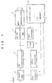
- FIG. 1 there is shown a block diagram illustrating an automatic broadcast wave tuning device for a RDS receiver to implement the automatic tuning operation in accordance with the present invention.
- an element 1 designates an antenna
- FM multiplex broadcast waves received by the antenna 1 are fed to a front end 2 for selectively receiving a desired broadcast wave of an selected broadcasting station, and thereby the selected broadcast wave is converted into an intermediate frequency (IF) and fed to a frequency discriminator (FM detector) 3.
- IF intermediate frequency
- FM detector frequency discriminator
- the front end 2 is under the control of a phase-locked loop (hereinafter referred to as PLL) circuit 6 including a programmable frequency divider (will be described in detail hereinafter), a dividing ratio of which is controlled by a controller 10 for providing the tuning operation.
- PLL phase-locked loop
- a discriminated output of the frequency discriminator 3 is fed to a multiplex (hereinafter referred to as MPX) demodulator circuit 5 through a noise canceller (hereinafter referred to as NK) 4 for deriving a L (left) channel signal and a R (right) channel signal therefrom in case of a stereophonic broadcasting.
- MPX multiplex
- NK noise canceller
- a RDS data signal is extracted from the discriminated output of the frequency discriminator 3 by passing through a 57 KHz band-pass filter 8 and fed to a RDS decoder 9 for decoding it into data readable by the controller 10.
- the controller 10 contains an AF memory 11, wherein stored are obtained informative data relating to the broadcasting stations in contact (aforesaid data PI, AF, PS, TP, TA and the like).
- a level detector 7 for detecting a received signal level (electric field strength level) based on the IF signal level fed from the frequency discriminator 3. The received signal level detected by the level detector 7 is then fed to the controller 10.
- FM multiplex broadcast waves received by the antenna 1 are fed to the front end 2, whereby a broadcast wave of a desired broadcasting station is selected and applied to the frequency discriminator 3 after being converted into the intermediate frequency.
- a discriminated output of the frequency discriminator 3 is fed to the MPX demodulator circuit 5 through the NK4, and which discriminated output is then decoded for outputting the Land R channel audio signals therefrom in case of the stereophonic broadcasting.
- the discriminated output of the frequency discriminator 3 is fed to the RDS decoder 9 through the 57 KHz band-pass filter 8, and thereby the discriminated output is decoded into data readable by the controller 10.
- the controller 10 takes in the informative data PI, AF, PS, TP, TA and the like, and stores the AF data in the AF memory 11.
- the level detector 7 detects a received signal level (electric field strength level) based on the IF signal level fed from the frequency discriminator 3, and feeds a detected resultant to the controller 10.
- the following table 1 illustrates the data stored in the AF memory 11.
- AF data lists are shown by characters of f l , f 2 , f 3 ... f N , whereby the AF data list f 3 , for example, is accompanied by a forbidden flag. It is assumed that data representing more than one broadcasting station are stored in the AF memory 11 at an AF frequency data storage area shown in the table 1.
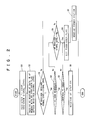
- step S1 the PI code of the broadcasting station presently tuned in is registered at the AF memory 11 contained in the controller 10 as being fed through the 57 KHz band-pass filter 8 and the RDS decoder 9, and all that the discriminated output of the frequency discriminator 3 is detected at the level detector 7 for deriving the received signal level therefrom and the derived signal level is also registered at the AF memory 11 in the controller 10.
- step S2 After registering the data at the AF memory 11 in the controller 10, the program goes to step S2.
- step S2 one of the stored AF data with no forbidden flag is selected and read from the AF memory 11, setting a frequency divisional ratio for the PLL circuit 6 based on the read out AF data, and then the front end 2 initiates the tune-in operation in accordance with the frequency divisional ratio being set for receiving the broadcast wave of the AF station that corresponds to the selected AF data.
- step S3 It is then determined, by comparison, at step S3 whether or not a received signal level of the AF station is greater than that of the former broadcasting station. If it is not, the program goes to step S7, whereas, if it is, it is then determined at step S4, after a predetermined period of time, whether or not the PI code of the AF station is detectable. If it is not, the program goes to step S9, whereas, if it is determined that the PI code is detectable at step S4, it is then checked at step S5 whether or not the detected PI code coincides with the PI code registered in the AF memory 11 at step S1.
- step S6 If it is not, the program goes to step S6, whereas, if it is, the program goes to step S8 for receiving the broadcast wave from the AF station, in other words, the reception of broadcast wave is switched from the former broadcasting station to a newly selected AF station.
- step S3 If it is determined at step S3 that the received signal level of the AF station is not greater than that of the former broadcasting station, or if it is determined at step S4 that the PI code of the AF station is not detectable and that the received signal level of the AF station is determined to be less than a predetermined signal level ofVo at step S9, the program goes to step S7 for receiving the broadcast wave transmitted by the former broadcasting station without setting the forbidden flag to the corresponding AF data. That is a state of a waiting for the next chance.
- step S9 if it is determined that the received signal level of the AF station detected at the signal level detector 7 is greater than the predetermined signal level V D , the program goes to step S6, setting the forbidden flag to the corresponding AF data.
- step S5 if it is determined at step S5 that the PI code of the AF station is not the same as that of the data stored in the AF memory 11, the program goes to step S6, writing the forbidden flag into the corresponding forbidden flag storage area (shown in the table 1) of the AF memory 11.
- step S6 Upon implementation of step S6 as described above, the,program goes to step S7, whereby the RDS receiver is brought back to tune in the former broadcasting station.
- the AF data accompanying the forbidden flag will no longer be selected in the operational step of S2, thus preventing the malfunction of the automatic broadcast wave tuning device while in the tuning operation.
- the received signal level of the AF station has been compared one after another with the signal level of the broadcasting station presently in reception, however, the present invention can be utilized in such an automatic system wherein a part or the whole frequencies that correspond to the stored AF data in the AF memory 11 may be checked successively for selecting the best broadcasting station to tune in.
- the forbidden flag is provided not only when it is determined that the received PI code is not identical with the one being stored while the AF station coincides with a RDS station in a different broadcasting network, but when it is assumed that the AF station is a non RDS station through the implementation of the operational step for determining whether or not the received signal level of the AF station is at or above the predetermined signal level in case of not receiving the PI code of the AF station. Therefore, it is possible to prevent the RDS receiver from causing malfunction in the operation against the RDS or non RDS broadcasting stations.
Landscapes
- Engineering & Computer Science (AREA)
- Signal Processing (AREA)
- Computer Hardware Design (AREA)
- Microelectronics & Electronic Packaging (AREA)
- Circuits Of Receivers In General (AREA)
- Channel Selection Circuits, Automatic Tuning Circuits (AREA)
Applications Claiming Priority (2)
| Application Number | Priority Date | Filing Date | Title |
|---|---|---|---|
| JP2268782A JP2669136B2 (ja) | 1990-10-05 | 1990-10-05 | Rds受信機の自動選局制御装置 |
| JP268782/90 | 1990-10-05 |
Publications (3)
| Publication Number | Publication Date |
|---|---|
| EP0479613A2 true EP0479613A2 (de) | 1992-04-08 |
| EP0479613A3 EP0479613A3 (en) | 1993-01-13 |
| EP0479613B1 EP0479613B1 (de) | 1997-02-26 |
Family
ID=17463211
Family Applications (1)
| Application Number | Title | Priority Date | Filing Date |
|---|---|---|---|
| EP91309131A Expired - Lifetime EP0479613B1 (de) | 1990-10-05 | 1991-10-04 | Automatische Rundfunkwellen-Abstimmungsvorrichtung für RDS-Empfänger |
Country Status (5)
| Country | Link |
|---|---|
| US (1) | US5220682A (de) |
| EP (1) | EP0479613B1 (de) |
| JP (1) | JP2669136B2 (de) |
| DE (1) | DE69124764T2 (de) |
| SG (1) | SG65594A1 (de) |
Cited By (3)
| Publication number | Priority date | Publication date | Assignee | Title |
|---|---|---|---|---|
| US5572201A (en) * | 1994-08-05 | 1996-11-05 | Federal Signal Corporation | Alerting device and system for abnormal situations |
| WO1997047086A1 (de) * | 1996-06-04 | 1997-12-11 | Robert Bosch Gmbh | Verfahren zur bereitstellung eines steuersignals für die steuerung eines rundfunkempfängers nach einem standortwechsel |
| WO1998000915A1 (de) * | 1996-06-29 | 1998-01-08 | Robert Bosch Gmbh | Verfahren zur speicherung der daten einer empfangenen trägerfrequenz eines rundfunksenders |
Families Citing this family (24)
| Publication number | Priority date | Publication date | Assignee | Title |
|---|---|---|---|---|
| DE4137000C2 (de) * | 1991-11-11 | 1994-06-09 | Opel Adam Ag | Verfahren zur feldstärkeabhängigen Auswertung von Rundfunkinformationen für Fahrzeuge |
| FI90383C (fi) * | 1992-03-09 | 1994-01-25 | Nokia Mobile Phones Ltd | Menetelmä radiopuhelimen referenssitaajuuden stabiloimiseksi |
| DE4233282A1 (de) * | 1992-10-02 | 1994-04-07 | Becker Autoradio | Verfahren zur Abstimmung eines Rundfunkempfängers unter Verwendung der RDS-Information |
| JP2841309B2 (ja) * | 1992-11-13 | 1998-12-24 | クラリオン株式会社 | 多重放送受信機 |
| JP3049164B2 (ja) * | 1992-12-25 | 2000-06-05 | 株式会社ケンウッド | データ多重放送用チューナ |
| JPH07297735A (ja) * | 1994-04-27 | 1995-11-10 | Pioneer Electron Corp | 多重放送受信方法及び受信機 |
| JP3538907B2 (ja) * | 1994-08-19 | 2004-06-14 | セイコーエプソン株式会社 | 移動体用の放送波受信装置 |
| WO1996021287A1 (en) * | 1994-12-29 | 1996-07-11 | Seiko Communications Systems, Inc. | Transmitting and displaying on a receiver information describing broadcast programs |
| DE19510220A1 (de) * | 1995-03-21 | 1996-09-26 | Blaupunkt Werke Gmbh | Rundfunkempfänger |
| US5790958A (en) * | 1995-10-16 | 1998-08-04 | Mmgt Enterprises, Inc. | Radio reception system for general purpose computer |
| JPH1051338A (ja) * | 1996-07-29 | 1998-02-20 | Honda Motor Co Ltd | 移動用fm多重放送受信装置 |
| JP3037146B2 (ja) * | 1996-07-30 | 2000-04-24 | 日本電気アイシーマイコンシステム株式会社 | データ格納方法およびその格納データの検索方法 |
| TW377533B (en) * | 1996-11-06 | 1999-12-21 | Koninkl Philips Electronics Nv | Radio receiver for receiving a main radio broadcast signal and a monolithic integrated circuit for use in such radio receiver |
| US6167494A (en) * | 1998-04-28 | 2000-12-26 | International Business Machine Corporation | Method and system for recovering from operating system failure |
| US6286063B1 (en) | 1998-06-08 | 2001-09-04 | Sonigistix Corporation | Microprocessor-controlled broadcast receiver embedded in an external peripheral with digital communications interface for bi-directional communication with a computer remotely located |
| DE19830688B4 (de) * | 1998-07-09 | 2009-11-19 | Delphi Technologies, Inc., Troy | Rundfunkempfänger für ein Fahrzeug |
| EP1032128A1 (de) * | 1999-02-23 | 2000-08-30 | Mannesmann VDO Aktiengesellschaft | Verfahren zur Verarbeitung von Sender- und Programmdaten in einem FM-RDS-Rundfunkempfänger |
| US6317882B1 (en) | 1999-12-21 | 2001-11-13 | Thomas D. Robbins | System and method for automatically reminding a user of a receiver that a broadcast is on a data stream |
| AU2446101A (en) * | 1999-12-21 | 2001-07-03 | Thomas D. Robbins | Automatic reminder system using transmitted id codes |
| US6463265B1 (en) * | 2001-06-05 | 2002-10-08 | International Business Machines Corp. | Data source hand-off in a broadcast-based data dissemination environment |
| EP1432156A1 (de) * | 2002-12-20 | 2004-06-23 | Sony International (Europe) GmbH | Verfahren zum Überwachen von Rundfunksignalen auf alternativen Frequenzen und Vorrichtung zur Verstärkungsregelung |
| US8099067B2 (en) * | 2005-08-03 | 2012-01-17 | Freescale Semiconductor, Inc. | Data signal system |
| US7822418B2 (en) * | 2007-05-14 | 2010-10-26 | Infineon Technologies Ag | Device playback using radio transmission |
| US9397773B2 (en) * | 2009-04-10 | 2016-07-19 | Qualcomm Incorporated | Methods and apparatus for enabling context sensitive interaction with distributed content |
Family Cites Families (8)
| Publication number | Priority date | Publication date | Assignee | Title |
|---|---|---|---|---|
| CH639084A5 (fr) * | 1979-04-27 | 1983-10-31 | Firmenich & Cie | Composes tricycliques oxygenes et leur utilisation a titre d'ingredients parfumants ou aromatisants. |
| DE3016118C2 (de) * | 1979-04-28 | 1984-10-31 | Pioneer Electronic Corp., Tokio/Tokyo | Schaltungsanordnung zur Unterdrückung von Störimpulsen in FM-Empfängern |
| JPS6467037A (en) * | 1987-09-07 | 1989-03-13 | Clarion Co Ltd | Receiving method in rds system radio |
| JP2569347B2 (ja) * | 1988-02-10 | 1997-01-08 | パイオニア株式会社 | ラジオデータ受信機 |
| JP2760552B2 (ja) * | 1988-03-17 | 1998-06-04 | 三洋電機株式会社 | 受信機 |
| JPH02104133A (ja) * | 1988-10-13 | 1990-04-17 | Pioneer Electron Corp | Rds受信機における受信周波数選択方法 |
| JP2693522B2 (ja) * | 1988-10-14 | 1997-12-24 | パイオニア株式会社 | Rds受信機の制御方法 |
| NL8900565A (nl) * | 1989-03-08 | 1990-10-01 | Philips Nv | Methode voor de verwerking van een radio data signaal, alsmede ontvanger voor de uitvoering van deze methode. |
-
1990
- 1990-10-05 JP JP2268782A patent/JP2669136B2/ja not_active Expired - Lifetime
-
1991
- 1991-09-26 US US07/765,943 patent/US5220682A/en not_active Expired - Fee Related
- 1991-10-04 SG SG1996008271A patent/SG65594A1/en unknown
- 1991-10-04 EP EP91309131A patent/EP0479613B1/de not_active Expired - Lifetime
- 1991-10-04 DE DE69124764T patent/DE69124764T2/de not_active Expired - Fee Related
Cited By (4)
| Publication number | Priority date | Publication date | Assignee | Title |
|---|---|---|---|---|
| US5572201A (en) * | 1994-08-05 | 1996-11-05 | Federal Signal Corporation | Alerting device and system for abnormal situations |
| WO1997047086A1 (de) * | 1996-06-04 | 1997-12-11 | Robert Bosch Gmbh | Verfahren zur bereitstellung eines steuersignals für die steuerung eines rundfunkempfängers nach einem standortwechsel |
| US6151489A (en) * | 1996-06-04 | 2000-11-21 | Robert Bosch Gmbh | Process for providing a control, signal for controlling a radio receiver after a change in position |
| WO1998000915A1 (de) * | 1996-06-29 | 1998-01-08 | Robert Bosch Gmbh | Verfahren zur speicherung der daten einer empfangenen trägerfrequenz eines rundfunksenders |
Also Published As
| Publication number | Publication date |
|---|---|
| JPH04144412A (ja) | 1992-05-18 |
| EP0479613B1 (de) | 1997-02-26 |
| US5220682A (en) | 1993-06-15 |
| DE69124764T2 (de) | 1997-06-12 |
| SG65594A1 (en) | 1999-06-22 |
| JP2669136B2 (ja) | 1997-10-27 |
| DE69124764D1 (de) | 1997-04-03 |
| EP0479613A3 (en) | 1993-01-13 |
Similar Documents
| Publication | Publication Date | Title |
|---|---|---|
| US5220682A (en) | Automatic broadcast wave tuning device for rds receiver | |
| US5428825A (en) | Method of selecting receiving frequency for RDS receiver | |
| EP0762683A2 (de) | Empfänger für den Empfang von RDS-Zusatzdaten in einem Rundfunkprogramm | |
| JPH01177721A (ja) | ラジオデータ受信機における受信周波数選択方法 | |
| JP2627284B2 (ja) | Rds受信機 | |
| EP0495136A2 (de) | Datenübertragungsverfahren bei RDS-Rundfunk | |
| EP0326747B1 (de) | Empfänger für RDS | |
| EP0326746A2 (de) | Empfänger für RDS | |
| EP0451990B2 (de) | Verfahren zum Wählen einer Frequenz für einen RDS-Empfänger | |
| JP2531692B2 (ja) | ラジオデ―タによる制御機能を有する受信機 | |
| JP3065442B2 (ja) | デジタルデータ多重システム用受信機 | |
| EP0552442B1 (de) | Empfänger für ein Radio-Daten-System | |
| JP2562821B2 (ja) | ラジオデータ受信機 | |
| JPH01177722A (ja) | ラジオデータ受信機における受信周波数選択方法 | |
| JP2529291B2 (ja) | ラジオデ―タ受信機におけるコ―ド判別方法 | |
| JPH0738597B2 (ja) | 自動追従方法 | |
| JP2522104B2 (ja) | Rds受信機 | |
| JPH02104133A (ja) | Rds受信機における受信周波数選択方法 | |
| JP2583548B2 (ja) | ラジオデータ受信機 | |
| KR20000033787A (ko) | Rds데이터를 이용한 교통정보 수신방법 | |
| JPH04235408A (ja) | Rds受信機 | |
| JPH04137812A (ja) | Rds受信機の自動選局制御装置 | |
| JPH04103226A (ja) | Rds受信機 | |
| JPH01177723A (ja) | ラジオデータ受信機における受信周波数選択方法 | |
| JPH03227133A (ja) | Rds受信機における受信方法 |
Legal Events
| Date | Code | Title | Description |
|---|---|---|---|
| PUAI | Public reference made under article 153(3) epc to a published international application that has entered the european phase |
Free format text: ORIGINAL CODE: 0009012 |
|
| AK | Designated contracting states |
Kind code of ref document: A2 Designated state(s): DE GB SE |
|
| PUAL | Search report despatched |
Free format text: ORIGINAL CODE: 0009013 |
|
| AK | Designated contracting states |
Kind code of ref document: A3 Designated state(s): DE GB SE |
|
| 17P | Request for examination filed |
Effective date: 19930422 |
|
| 17Q | First examination report despatched |
Effective date: 19950726 |
|
| GRAG | Despatch of communication of intention to grant |
Free format text: ORIGINAL CODE: EPIDOS AGRA |
|
| GRAH | Despatch of communication of intention to grant a patent |
Free format text: ORIGINAL CODE: EPIDOS IGRA |
|
| GRAH | Despatch of communication of intention to grant a patent |
Free format text: ORIGINAL CODE: EPIDOS IGRA |
|
| GRAA | (expected) grant |
Free format text: ORIGINAL CODE: 0009210 |
|
| AK | Designated contracting states |
Kind code of ref document: B1 Designated state(s): DE GB SE |
|
| REF | Corresponds to: |
Ref document number: 69124764 Country of ref document: DE Date of ref document: 19970403 |
|
| PLBE | No opposition filed within time limit |
Free format text: ORIGINAL CODE: 0009261 |
|
| STAA | Information on the status of an ep patent application or granted ep patent |
Free format text: STATUS: NO OPPOSITION FILED WITHIN TIME LIMIT |
|
| 26N | No opposition filed | ||
| PGFP | Annual fee paid to national office [announced via postgrant information from national office to epo] |
Ref country code: GB Payment date: 19981001 Year of fee payment: 8 |
|
| PGFP | Annual fee paid to national office [announced via postgrant information from national office to epo] |
Ref country code: SE Payment date: 19981006 Year of fee payment: 8 |
|
| PGFP | Annual fee paid to national office [announced via postgrant information from national office to epo] |
Ref country code: DE Payment date: 19981012 Year of fee payment: 8 |
|
| PG25 | Lapsed in a contracting state [announced via postgrant information from national office to epo] |
Ref country code: GB Free format text: LAPSE BECAUSE OF NON-PAYMENT OF DUE FEES Effective date: 19991004 |
|
| PG25 | Lapsed in a contracting state [announced via postgrant information from national office to epo] |
Ref country code: SE Free format text: THE PATENT HAS BEEN ANNULLED BY A DECISION OF A NATIONAL AUTHORITY Effective date: 19991030 |
|
| GBPC | Gb: european patent ceased through non-payment of renewal fee |
Effective date: 19991004 |
|
| EUG | Se: european patent has lapsed |
Ref document number: 91309131.0 |
|
| PG25 | Lapsed in a contracting state [announced via postgrant information from national office to epo] |
Ref country code: DE Free format text: LAPSE BECAUSE OF NON-PAYMENT OF DUE FEES Effective date: 20000801 |