EP0475098A2 - Microscope à rayons X - Google Patents
Microscope à rayons X Download PDFInfo
- Publication number
- EP0475098A2 EP0475098A2 EP91113635A EP91113635A EP0475098A2 EP 0475098 A2 EP0475098 A2 EP 0475098A2 EP 91113635 A EP91113635 A EP 91113635A EP 91113635 A EP91113635 A EP 91113635A EP 0475098 A2 EP0475098 A2 EP 0475098A2
- Authority
- EP
- European Patent Office
- Prior art keywords
- ray
- microscope according
- source
- mirror
- condenser
- Prior art date
- Legal status (The legal status is an assumption and is not a legal conclusion. Google has not performed a legal analysis and makes no representation as to the accuracy of the status listed.)
- Granted
Links
Images
Classifications
-
- G—PHYSICS
- G21—NUCLEAR PHYSICS; NUCLEAR ENGINEERING
- G21K—HANDLING OF PARTICLES OR IONISING RADIATION NOT OTHERWISE PROVIDED FOR; IRRADIATION DEVICES; GAMMA RAY OR X-RAY MICROSCOPES
- G21K7/00—Gamma- or X-ray microscopes
Definitions
- X-ray microscopes which differ more or less in their optical structure with regard to the beam source used, the optics for focusing the X-ray beam on the object to be examined and those for imaging the object on the imaging X-ray detector used.
- X-ray microscopes have been described in which mirror optics are used to image the object on the detector, for example Wolter optics that image the object with grazing incidence of the X-rays.
- the quality of the microscopic image generated with such microscopes is not particularly good, since the mirror optics are sometimes subject to considerable image errors.
- image errors - in the case of mirror optics that work under grazing incidence this is, for example, the so-called angular tangent error - limit the resolution of the optics aperture, which is possible in principle and which can be achieved with the microscope.
- zone plates are used both for focusing the X-radiation on the object and for imaging the object on the detector. Similar to very thin lenses, these zone plates allow a largely image-free and thus high-resolution image of the object. However, they have a significantly poorer efficiency than mirror optics. In practice, it is between 5% and 15%, i.e. only a maximum of 15% of the X-rays incident on the zone plate are used for the imaging.
- zone plate used as a condenser not only serves to focus the X-ray radiation on the object, but also acts as a monochromator and separates the monochromatic radiation required for high-resolution imaging from the more or less extensive wavelength range emitted by the X-ray source. This is done simply by means of a suitable pinhole on the optical axis, which has the effect that only one of the monochromatic images resulting from the wavelength dependence of the focal length of the zone plate on the optical axis passes through the diaphragm.
- the X-ray microscope described is relatively weak due to the use of zone plates with the mentioned low efficiency, so that long exposure times result, which e.g. can cause motion blur during exposure when recording live cells.
- One is therefore dependent on X-ray sources that are as intensive as possible.
- synchrotron radiation from electron storage rings is used almost exclusively for X-ray microscopy.
- this has the disadvantage that the X-ray microscope is not self-sufficient, i.e. the user is bound to one of the few electron storage rings in terms of space and the measurement time available to him.
- the so-called plasma focus source is also known as the X-ray source.
- X-ray sources for example described in DE-OS 33 32 711, do not emit X-rays continuously, but instead deliver individual short X-ray pulses which are followed by a relatively long dead time during which the capacitors of the X-ray source have to be recharged.
- the X-ray energy contained in a pulse is in many cases not sufficient,
- the available X-ray energy is optimally used.
- the use of mirror optics on the illumination side does not have a disadvantage, since the image errors of the mirror condenser are significantly less critical when illuminated than on the imaging side of the microscope.
- 20 to 30 times the light gain is achieved compared to a zone plate on the lighting side.
- the mirror condenser cannot be used as a monochromator, this is not necessary either, since X-ray sources such as, for example the plasma focus already provides a sufficiently intense monochromatic line radiation.
- the zone plate with its excellent imaging properties can be retained on the imaging side.
- the mirror condenser can be a segment of an ellipsoid that focuses the X-ray radiation on the object with grazing incidence. It is expedient if the mirror condenser is coated with a multilayer to increase the reflectivity. In this way, the efficiency of the microscope can be further improved.
- the zone plate used for imaging the object on the detector is expediently a phase zone plate which has a higher efficiency than an amplitude zone plate.
- the condenser images the X-ray source directly onto the object in the manner of the so-called “critical lighting”.
- critical lighting which is usually used in microscopy
- the mirror condenser is protected by one or more foils through which the X-ray beam passes.
- the sensitive mirror surfaces can be shielded against dust and dirt from the environment, possibly also against vapors from the plasma focus source, which would otherwise be deposited on the optical surfaces of the condenser and reduce its efficiency.
- Either a photo plate or an X-ray sensitive CCD camera can be used as the detector.
- An image memory is expediently connected downstream of the camera, into which the images of the objects to be examined, each generated with an x-ray pulse, are then read and further processed, for example, using the known methods of image processing.
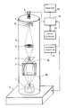
- (1) denotes the X-ray source.
- This X-ray source is a plasma focus source of the type as described in DE-OS 33 32 711.
- This plasma focus source briefly provides a point-like plasma which emits X-rays with a dominant emission wavelength on the Lyman-a line of the six-fold ionized nitrogen.
- the plasma focus source (1) is operated with a capacitor bank (2) which is electrically charged in the period between the discharges.
- the X-ray radiation emanating from the plasma focus (1 a) is focused on the object placed on a slide (4) with the aid of a mirror condenser (3).
- the mirror condenser (3) has the shape of an ellipsoid of revolution and reflects the X-rays striking its mirror surfaces under grazing incidence.
- the mirror condenser (3) is closed at both ends by a film (15) and (16), which protects the sensitive mirror surfaces against dirt.
- the foils are made of a material that is as weakly absorbent as possible in the spectral range of the X-rays, e.g. Made polyimide.
- micro zone plate (5) is arranged above the object level.
- This micro zone plate represents the actual imaging optics of the X-ray microscope. Its distance from the object plane is greatly exaggerated in the representation. In fact, the micro zone plate has a diameter of approximately 20-50 ⁇ m and is only a few tenths of a millimeter above the object to be examined.
- the micro zone plate (5) images the object in a greatly enlarged manner on a detector (6).
- the detector (6) is a solid-state camera, such as that which can be obtained from Valvo under the name NXA 1011, and which is sensitized to X-rays by removing the cover glass and the photosensitive surface with a fluorescent dye such as Gd 2 0 2 S: Tb was occupied.
- the CCD camera (6) is attached to a carrier (7) which, as indicated by the arrow, can be moved along the optical axis with the aid of an adjusting device (8) for the purpose of focusing.
- the components of the X-ray microscope described above are located in a cylindrical column (9) built onto the capacitor bank (2), which is under vacuum or with a gas which is only weakly absorbent in the area of the X-ray radiation used, e.g. Helium or hydrogen is filled.
- a gas which is only weakly absorbent in the area of the X-ray radiation used e.g. Helium or hydrogen is filled.
- the signal lines of the CCD camera (6) are passed through the setting device (8) and connected to an electronic unit (10), which reads out the image from the CCD camera (6).
- This camera electronics (10) is synchronized via a control unit (11) with the electronics (not shown) for the operation of the plasma focus source in such a way that after each x-ray pulse emitted by the plasma focus source (1) an image is drawn in and stored in an image memory (13) .
- the images stored there can then be viewed using a monitor (12) which is also connected to the electronic unit (10).
Landscapes
- Physics & Mathematics (AREA)
- Engineering & Computer Science (AREA)
- General Engineering & Computer Science (AREA)
- High Energy & Nuclear Physics (AREA)
- Analysing Materials By The Use Of Radiation (AREA)
- Transition And Organic Metals Composition Catalysts For Addition Polymerization (AREA)
- Liquid Crystal Substances (AREA)
- Transforming Light Signals Into Electric Signals (AREA)
Applications Claiming Priority (2)
| Application Number | Priority Date | Filing Date | Title |
|---|---|---|---|
| DE4027285 | 1990-08-29 | ||
| DE4027285A DE4027285A1 (de) | 1990-08-29 | 1990-08-29 | Roentgenmikroskop |
Publications (3)
| Publication Number | Publication Date |
|---|---|
| EP0475098A2 true EP0475098A2 (fr) | 1992-03-18 |
| EP0475098A3 EP0475098A3 (en) | 1992-07-22 |
| EP0475098B1 EP0475098B1 (fr) | 1996-02-07 |
Family
ID=6413137
Family Applications (1)
| Application Number | Title | Priority Date | Filing Date |
|---|---|---|---|
| EP91113635A Expired - Lifetime EP0475098B1 (fr) | 1990-08-29 | 1991-08-14 | Microscope à rayons X |
Country Status (5)
| Country | Link |
|---|---|
| US (1) | US5222113A (fr) |
| EP (1) | EP0475098B1 (fr) |
| JP (1) | JP3133103B2 (fr) |
| AT (1) | ATE134065T1 (fr) |
| DE (2) | DE4027285A1 (fr) |
Cited By (4)
| Publication number | Priority date | Publication date | Assignee | Title |
|---|---|---|---|---|
| WO1995008174A1 (fr) * | 1993-09-15 | 1995-03-23 | Carl-Zeiss-Stiftung Handelnd Als Carl Zeiss | Microscope a rayons x a contraste de phase |
| WO1997025723A3 (fr) * | 1996-01-12 | 1997-10-02 | Niemann Bastian | Radiomicroscope a lentilles zonees |
| US6128364A (en) * | 1996-01-10 | 2000-10-03 | Leica Microsystems Lithography Gmbh | Condenser-monochromator arrangement for X-radiation |
| WO2009030390A1 (fr) * | 2007-09-04 | 2009-03-12 | Fraunhofer-Gesellschaft zur Förderung der angewandten Forschung e.V. | Dispositif et procédé pour microscopie xuv |
Families Citing this family (35)
| Publication number | Priority date | Publication date | Assignee | Title |
|---|---|---|---|---|
| US5528646A (en) * | 1992-08-27 | 1996-06-18 | Olympus Optical Co., Ltd. | Sample vessel for X-ray microscopes |
| US6091796A (en) * | 1994-11-23 | 2000-07-18 | Thermotrex Corporation | Scintillator based microscope |
| US5965065A (en) * | 1994-12-05 | 1999-10-12 | Powell; Stephen Forbes | Method of filtering x-rays |
| KR100606490B1 (ko) * | 1997-04-08 | 2006-07-31 | 엑스레이 테크놀로지즈 피티와이 리미티드 | 극소형 대상물의 고 분해능 X-ray 이미징 |
| GB9815968D0 (en) * | 1998-07-23 | 1998-09-23 | Bede Scient Instr Ltd | X-ray focusing apparatus |
| DE19956782C2 (de) * | 1999-11-25 | 2001-11-15 | Lutz Kipp | Optisches Fokussierelement, Meßsystem und Apparatur mit einem solchen optischen Element und Verwendung desselben |
| EP1126477A3 (fr) * | 2000-02-14 | 2003-06-18 | Leica Microsystems Lithography GmbH | Procédé d'examen de structures dans un substrat sémiconducteur |
| US6195272B1 (en) | 2000-03-16 | 2001-02-27 | Joseph E. Pascente | Pulsed high voltage power supply radiography system having a one to one correspondence between low voltage input pulses and high voltage output pulses |
| JP4220170B2 (ja) * | 2002-03-22 | 2009-02-04 | 浜松ホトニクス株式会社 | X線像拡大装置 |
| EP1446813B1 (fr) * | 2002-05-10 | 2010-11-10 | Carl Zeiss SMT AG | Microscope aux rayons x reflechissant concus pour examiner des objets presentant des longueurs d'onde = 100nm en reflexion |
| US7245696B2 (en) * | 2002-05-29 | 2007-07-17 | Xradia, Inc. | Element-specific X-ray fluorescence microscope and method of operation |
| DE60334910D1 (de) * | 2002-08-02 | 2010-12-23 | X Ray Optical Sys Inc | Optische Vorrichtung aus einer Vielzahl von gekrümmten optischen Kristallen zum Fokussieren von Röntgenstrahlen |
| US7365909B2 (en) * | 2002-10-17 | 2008-04-29 | Xradia, Inc. | Fabrication methods for micro compounds optics |
| US7072442B1 (en) * | 2002-11-20 | 2006-07-04 | Kla-Tencor Technologies Corporation | X-ray metrology using a transmissive x-ray optical element |
| DE10254026C5 (de) * | 2002-11-20 | 2009-01-29 | Incoatec Gmbh | Reflektor für Röntgenstrahlung |
| US7119953B2 (en) * | 2002-12-27 | 2006-10-10 | Xradia, Inc. | Phase contrast microscope for short wavelength radiation and imaging method |
| DE10319269A1 (de) * | 2003-04-25 | 2004-11-25 | Carl Zeiss Sms Gmbh | Abbildungssystem für ein, auf extrem ultravioletter (EUV) Strahlung basierendem Mikroskop |
| DE10334169A1 (de) | 2003-07-26 | 2005-02-24 | Bruker Axs Gmbh | Gekapselter Röntgenspiegel |
| US7170969B1 (en) * | 2003-11-07 | 2007-01-30 | Xradia, Inc. | X-ray microscope capillary condenser system |
| US20050211910A1 (en) * | 2004-03-29 | 2005-09-29 | Jmar Research, Inc. | Morphology and Spectroscopy of Nanoscale Regions using X-Rays Generated by Laser Produced Plasma |
| US7302043B2 (en) * | 2004-07-27 | 2007-11-27 | Gatan, Inc. | Rotating shutter for laser-produced plasma debris mitigation |
| US7452820B2 (en) * | 2004-08-05 | 2008-11-18 | Gatan, Inc. | Radiation-resistant zone plates and method of manufacturing thereof |
| US7466796B2 (en) * | 2004-08-05 | 2008-12-16 | Gatan, Inc. | Condenser zone plate illumination for point X-ray sources |
| US7231017B2 (en) * | 2005-07-27 | 2007-06-12 | Physical Optics Corporation | Lobster eye X-ray imaging system and method of fabrication thereof |
| WO2007016484A2 (fr) | 2005-08-01 | 2007-02-08 | The Research Foundation Of State University Of New York | Systemes d'imagerie par rayons x utilisant des optiques de monochromatisation incurvees a focalisation ponctuelle |
| US20070108387A1 (en) * | 2005-11-14 | 2007-05-17 | Xradia, Inc. | Tunable x-ray fluorescence imager for multi-element analysis |
| DE102005056404B4 (de) * | 2005-11-23 | 2013-04-25 | Helmholtz-Zentrum Berlin Für Materialien Und Energie Gmbh | Röntgenmikroskop mit Kondensor-Monochromator-Anordnung hoher spektraler Auflösung |
| US7499521B2 (en) * | 2007-01-04 | 2009-03-03 | Xradia, Inc. | System and method for fuel cell material x-ray analysis |
| US9291578B2 (en) | 2012-08-03 | 2016-03-22 | David L. Adler | X-ray photoemission microscope for integrated devices |
| US9129715B2 (en) | 2012-09-05 | 2015-09-08 | SVXR, Inc. | High speed x-ray inspection microscope |
| US20160086681A1 (en) * | 2014-09-24 | 2016-03-24 | Carl Zeiss X-ray Microscopy, Inc. | Zone Plate and Method for Fabricating Same Using Conformal Coating |
| CN114424054B (zh) * | 2019-06-24 | 2024-03-22 | Sms集团有限公司 | 用于确定多晶产品的材料特性的设备和方法 |
| DE102019124919B4 (de) | 2019-09-17 | 2021-08-26 | Ri Research Instruments Gmbh | Mikroskopisches System zur Prüfung von Strukturen und Defekten auf EUV-Lithographie-Photomasken |
| JP7572033B2 (ja) * | 2020-10-23 | 2024-10-23 | 株式会社リガク | 結像型x線顕微鏡 |
| DE102024002214A1 (de) * | 2024-06-25 | 2026-01-08 | Helmholtz-Zentrum Berlin für Materialien und Energie Gesellschaft mit beschränkter Haftung | Reflexionsoptik und Mikroskop mit Reflexionsoptik |
Family Cites Families (7)
| Publication number | Priority date | Publication date | Assignee | Title |
|---|---|---|---|---|
| DE3332711A1 (de) * | 1983-09-10 | 1985-03-28 | Fa. Carl Zeiss, 7920 Heidenheim | Vorrichtung zur erzeugung einer plasmaquelle mit hoher strahlungsintensitaet im roentgenbereich |
| JPS6221223A (ja) * | 1985-07-19 | 1987-01-29 | Shimadzu Corp | 軟x線用投影結像装置 |
| DE3642457A1 (de) * | 1986-12-12 | 1988-06-30 | Zeiss Carl Fa | Roentgen-mikroskop |
| US4912737A (en) * | 1987-10-30 | 1990-03-27 | Hamamatsu Photonics K.K. | X-ray image observing device |
| JP2844703B2 (ja) * | 1989-08-09 | 1999-01-06 | 株式会社ニコン | 結像型軟x線顕微鏡装置 |
| JP2883122B2 (ja) * | 1989-10-20 | 1999-04-19 | オリンパス光学工業株式会社 | X線顕微鏡 |
| JP2921038B2 (ja) * | 1990-06-01 | 1999-07-19 | キヤノン株式会社 | X線を用いた観察装置 |
-
1990
- 1990-08-29 DE DE4027285A patent/DE4027285A1/de not_active Withdrawn
-
1991
- 1991-08-14 DE DE59107380T patent/DE59107380D1/de not_active Expired - Fee Related
- 1991-08-14 EP EP91113635A patent/EP0475098B1/fr not_active Expired - Lifetime
- 1991-08-14 AT AT91113635T patent/ATE134065T1/de not_active IP Right Cessation
- 1991-08-27 JP JP03214876A patent/JP3133103B2/ja not_active Expired - Fee Related
- 1991-08-29 US US07/751,792 patent/US5222113A/en not_active Expired - Lifetime
Cited By (4)
| Publication number | Priority date | Publication date | Assignee | Title |
|---|---|---|---|---|
| WO1995008174A1 (fr) * | 1993-09-15 | 1995-03-23 | Carl-Zeiss-Stiftung Handelnd Als Carl Zeiss | Microscope a rayons x a contraste de phase |
| US6128364A (en) * | 1996-01-10 | 2000-10-03 | Leica Microsystems Lithography Gmbh | Condenser-monochromator arrangement for X-radiation |
| WO1997025723A3 (fr) * | 1996-01-12 | 1997-10-02 | Niemann Bastian | Radiomicroscope a lentilles zonees |
| WO2009030390A1 (fr) * | 2007-09-04 | 2009-03-12 | Fraunhofer-Gesellschaft zur Förderung der angewandten Forschung e.V. | Dispositif et procédé pour microscopie xuv |
Also Published As
| Publication number | Publication date |
|---|---|
| JP3133103B2 (ja) | 2001-02-05 |
| DE4027285A1 (de) | 1992-03-05 |
| JPH04262300A (ja) | 1992-09-17 |
| EP0475098A3 (en) | 1992-07-22 |
| DE59107380D1 (de) | 1996-03-21 |
| EP0475098B1 (fr) | 1996-02-07 |
| ATE134065T1 (de) | 1996-02-15 |
| US5222113A (en) | 1993-06-22 |
Similar Documents
| Publication | Publication Date | Title |
|---|---|---|
| EP0475098B1 (fr) | Microscope à rayons X | |
| EP0116321B1 (fr) | Spectromètre infrarouge | |
| DE3148091C2 (de) | Vorrichtung zum Untersuchen einer Probe in einem Rasterelektronenmikroskop | |
| DE10156275B4 (de) | Detektoranordnung und Detektionsverfahren | |
| DE102009029831A1 (de) | Vorrichtung und Verfahren für die Mehr-Photonen-Fluoreszenzmikroskopie zur Gewinnung von Informationen aus biologischem Gewebe | |
| DE102004053730B4 (de) | Verfahren und Anordnung zur Unterdrückung von Falschlicht | |
| US5912939A (en) | Soft x-ray microfluoroscope | |
| DE102013107736A1 (de) | Röntgenprüfvorrichtung für die Materialprüfung und Verfahren zur Erzeugung hochaufgelöster Projektionen eines Prüflings mittels Röntgenstrahlen | |
| WO1998035214A9 (fr) | Microfluoroscope a rayons x mous | |
| EP1691217B1 (fr) | Procédé et appareil pour lire des vues radiographiques enregistrées dans un écran luminescent | |
| EP1691216A1 (fr) | Système radiographique et méthode d'enregistrement des radiographies dans des feuilles photostimulables | |
| DE69403129T2 (de) | Röntgenstrahlen-Analysegerät | |
| DE9110927U1 (de) | Glasfaser-Beleuchtungseinrichtung für ein Mikroskop | |
| DE102015209954B4 (de) | Vorrichtung und Verfahren zur multimodalen Bildgebung | |
| DE2823458A1 (de) | Optische vorrichtung zur richtungsveraenderung eines lichtstrahlenbuendels | |
| DE2640260C3 (de) | Durchstrahl ungs-Raster-Korpuskularstrahlniikroskop | |
| DE2742264B2 (de) | Verfahren zur Abbildung eines Objektes mit geringer Vergrößerung mittels eines Korpuskularstrahlgeräts, insbesondere eines Elektronen-Mikroskops und Korpuskularstrahlgerät zur Durchführung des Verfahrens | |
| DE102022125117A1 (de) | Lichtblattmikroskop | |
| DE1058166B (de) | Elektronenmikroskop | |
| DE9110926U1 (de) | Blitzlicht-Beleuchtungseinrichtung für ein Mikroskop | |
| WO2009146787A1 (fr) | Dispositif permettant de lire des écrans à mémoire pour images de radiographie | |
| DE102005056404A1 (de) | Röntgenmikroskop mit Kondensor-Monochromator-Anordnung hoher spektraler Auflösung | |
| DE102007041939A1 (de) | Vorrichtung und Verfahren für die XUV-Mikroskopie | |
| DE2627214C2 (de) | Gerät zum Durchleuchten mittels durchdringender Strahlung mit einem Bildwandler, dessen Ausgangsbild über einen Bildverstärker auf die Aufnahmeröhre eines Fernsehsystems fällt | |
| WO2002090947A2 (fr) | Microscope pour analyse de la fluctuation de fluorescence et module de mesure ou module de balayage de la fluctuation de fluorescence et procede de mesure de la fluctuation de fluorescence ainsi que procede et dispositif d'alignement d'un microscope pour analyse de la fluctuation de fluorescence |
Legal Events
| Date | Code | Title | Description |
|---|---|---|---|
| PUAI | Public reference made under article 153(3) epc to a published international application that has entered the european phase |
Free format text: ORIGINAL CODE: 0009012 |
|
| AK | Designated contracting states |
Kind code of ref document: A2 Designated state(s): AT CH DE FR GB LI NL SE |
|
| PUAL | Search report despatched |
Free format text: ORIGINAL CODE: 0009013 |
|
| AK | Designated contracting states |
Kind code of ref document: A3 Designated state(s): AT CH DE FR GB LI NL SE |
|
| 17P | Request for examination filed |
Effective date: 19930113 |
|
| 17Q | First examination report despatched |
Effective date: 19940727 |
|
| GRAA | (expected) grant |
Free format text: ORIGINAL CODE: 0009210 |
|
| AK | Designated contracting states |
Kind code of ref document: B1 Designated state(s): AT CH DE FR GB LI NL SE |
|
| REF | Corresponds to: |
Ref document number: 134065 Country of ref document: AT Date of ref document: 19960215 Kind code of ref document: T |
|
| REF | Corresponds to: |
Ref document number: 59107380 Country of ref document: DE Date of ref document: 19960321 |
|
| ET | Fr: translation filed | ||
| GBT | Gb: translation of ep patent filed (gb section 77(6)(a)/1977) |
Effective date: 19960417 |
|
| PLBE | No opposition filed within time limit |
Free format text: ORIGINAL CODE: 0009261 |
|
| STAA | Information on the status of an ep patent application or granted ep patent |
Free format text: STATUS: NO OPPOSITION FILED WITHIN TIME LIMIT |
|
| 26N | No opposition filed | ||
| REG | Reference to a national code |
Ref country code: GB Ref legal event code: IF02 |
|
| PGFP | Annual fee paid to national office [announced via postgrant information from national office to epo] |
Ref country code: NL Payment date: 20080813 Year of fee payment: 18 Ref country code: DE Payment date: 20080822 Year of fee payment: 18 Ref country code: CH Payment date: 20080814 Year of fee payment: 18 |
|
| PGFP | Annual fee paid to national office [announced via postgrant information from national office to epo] |
Ref country code: AT Payment date: 20080814 Year of fee payment: 18 Ref country code: FR Payment date: 20080813 Year of fee payment: 18 |
|
| PGFP | Annual fee paid to national office [announced via postgrant information from national office to epo] |
Ref country code: GB Payment date: 20080821 Year of fee payment: 18 |
|
| PGFP | Annual fee paid to national office [announced via postgrant information from national office to epo] |
Ref country code: SE Payment date: 20080815 Year of fee payment: 18 |
|
| REG | Reference to a national code |
Ref country code: CH Ref legal event code: PL Ref country code: NL Ref legal event code: V1 Effective date: 20100301 |
|
| GBPC | Gb: european patent ceased through non-payment of renewal fee |
Effective date: 20090814 |
|
| PG25 | Lapsed in a contracting state [announced via postgrant information from national office to epo] |
Ref country code: CH Free format text: LAPSE BECAUSE OF NON-PAYMENT OF DUE FEES Effective date: 20090831 Ref country code: LI Free format text: LAPSE BECAUSE OF NON-PAYMENT OF DUE FEES Effective date: 20090831 |
|
| REG | Reference to a national code |
Ref country code: FR Ref legal event code: ST Effective date: 20100430 |
|
| PG25 | Lapsed in a contracting state [announced via postgrant information from national office to epo] |
Ref country code: AT Free format text: LAPSE BECAUSE OF NON-PAYMENT OF DUE FEES Effective date: 20090814 |
|
| PG25 | Lapsed in a contracting state [announced via postgrant information from national office to epo] |
Ref country code: NL Free format text: LAPSE BECAUSE OF NON-PAYMENT OF DUE FEES Effective date: 20100301 Ref country code: FR Free format text: LAPSE BECAUSE OF NON-PAYMENT OF DUE FEES Effective date: 20090831 Ref country code: DE Free format text: LAPSE BECAUSE OF NON-PAYMENT OF DUE FEES Effective date: 20100302 |
|
| PG25 | Lapsed in a contracting state [announced via postgrant information from national office to epo] |
Ref country code: GB Free format text: LAPSE BECAUSE OF NON-PAYMENT OF DUE FEES Effective date: 20090814 |
|
| PG25 | Lapsed in a contracting state [announced via postgrant information from national office to epo] |
Ref country code: SE Free format text: LAPSE BECAUSE OF NON-PAYMENT OF DUE FEES Effective date: 20090815 |