EP0474232A2 - Durchsichtige berührungsempfindliche Eingabescheibe - Google Patents
Durchsichtige berührungsempfindliche Eingabescheibe Download PDFInfo
- Publication number
- EP0474232A2 EP0474232A2 EP91115018A EP91115018A EP0474232A2 EP 0474232 A2 EP0474232 A2 EP 0474232A2 EP 91115018 A EP91115018 A EP 91115018A EP 91115018 A EP91115018 A EP 91115018A EP 0474232 A2 EP0474232 A2 EP 0474232A2
- Authority
- EP
- European Patent Office
- Prior art keywords
- input
- area
- sensors
- touched
- operation panel
- Prior art date
- Legal status (The legal status is an assumption and is not a legal conclusion. Google has not performed a legal analysis and makes no representation as to the accuracy of the status listed.)
- Granted
Links
Images


Classifications
-
- G—PHYSICS
- G06—COMPUTING OR CALCULATING; COUNTING
- G06F—ELECTRIC DIGITAL DATA PROCESSING
- G06F3/00—Input arrangements for transferring data to be processed into a form capable of being handled by the computer; Output arrangements for transferring data from processing unit to output unit, e.g. interface arrangements
- G06F3/01—Input arrangements or combined input and output arrangements for interaction between user and computer
- G06F3/03—Arrangements for converting the position or the displacement of a member into a coded form
- G06F3/033—Pointing devices displaced or positioned by the user, e.g. mice, trackballs, pens or joysticks; Accessories therefor
-
- G—PHYSICS
- G03—PHOTOGRAPHY; CINEMATOGRAPHY; ANALOGOUS TECHNIQUES USING WAVES OTHER THAN OPTICAL WAVES; ELECTROGRAPHY; HOLOGRAPHY
- G03G—ELECTROGRAPHY; ELECTROPHOTOGRAPHY; MAGNETOGRAPHY
- G03G15/00—Apparatus for electrographic processes using a charge pattern
- G03G15/50—Machine control of apparatus for electrographic processes using a charge pattern, e.g. regulating differents parts of the machine, multimode copiers, microprocessor control
- G03G15/5016—User-machine interface; Display panels; Control console
-
- G—PHYSICS
- G06—COMPUTING OR CALCULATING; COUNTING
- G06F—ELECTRIC DIGITAL DATA PROCESSING
- G06F3/00—Input arrangements for transferring data to be processed into a form capable of being handled by the computer; Output arrangements for transferring data from processing unit to output unit, e.g. interface arrangements
- G06F3/01—Input arrangements or combined input and output arrangements for interaction between user and computer
- G06F3/03—Arrangements for converting the position or the displacement of a member into a coded form
- G06F3/041—Digitisers, e.g. for touch screens or touch pads, characterised by the transducing means
- G06F3/043—Digitisers, e.g. for touch screens or touch pads, characterised by the transducing means using propagating acoustic waves
Definitions
- the present invention relates to a signal input device for inputting required data in response to points designated by touching a control panel.
- One method is to use a key board on which data are input by keys. Each key is provided with a sensor (e.g. a contact switch) for detecting the input. This method is mainly used in electronic appliances.
- Another method is to use, in addition to the key board, a signal input device designed to designate an image-reading area or an image-non-reading area.
- This type of signal input devices adopt the following methods: One method is for an operator to overlap a copying image on a lattice-scaled transparent sheet, and read the scales on the X-axis and Y-axis so as to input point by point through a ten-key key board.
- a third method is to provide arrays of switches equally spaced along the X-axis and Y-axis, respectively on an original glass plate, and enable an operator to input a coordinate designated by switches.
- a fourth method is to provide a planar matrix array sensor on a cover covering an original, and to input into the sensor by an input pen.
- the first and second methods can be economically achieved, but are not efficient in operation.
- the third method is also inefficient because of the dual operations of the X-axis and Y-axis.
- the fourth method is more efficient than the other methods but disadvantageously costly because of the expensive matrix array.
- the glass plate must be completely transparent and exactly flat so as to avoid erroneous readings, and therefore, a special tray or the like must be used for supporting the matrix array sensor. The original must be shifted from the glass plate to the tray.
- Japanese Laid-Open Patent Publication No. 63-244068 proposes a device which is used in cooperation with a ready-made original glass plate so as to designate copying parts of the original placed on the glass plate.
- This device includes an input pen incorporating an oscillator and at least three vibration detectors around the glass plate. When an operator touches the original glass plate with the input pen, the three detectors detect time intervals on the basis of reception of signals from the touching so as to specify the touching points.
- the 63-244068 Publication does not disclose a means or structure for specifying the touching points in detail but it is presumed that the cost will be reduced because a ready-made glass plate is used, and no key input device or matrix array is required.
- the first and fourth method require an extra input device for inputting copying data in addition to a key input device for designating the inputting areas.
- the 63-244068 Publication discloses the designation of an imputting area but fails to disclose that the glass plate is used as the input device.
- the signal input device of this invention which overcomes the above-discussed and numerous other disadvantages and deficiencies of the prior art, comprises an operation panel including an input area in which data are input by touching the operation panel, a plurality of sensors located at different places on the operation panel, the sensors receiving vibrations propagated from a touched point on the operation panel, a detection circuit for detecting the time at which the sensors receive the vibrations, an arithmetic means for identifying the position of the touched point, a memory means for storing numerical values whereby the input area is divided into a plurality of minor areas, and means for judging which minor areas the touched points belong to, on the basis of the arithmetic results of the numerical values and data about the positions of the touched points.
- a signal input device comprising a transparent glass panel a first area in which an original is placed and a second area in which the original is not placed, a plurality of sensors located at the second place, the sensors receiving vibrations propagated from a touched point on the glass panel, a detection circuit for detecting the time at which the sensors receive the vibrations, an arithmetic means for identifying the position of the touched point on the basis of the detected time, a memory means for storing the second area of the glass panel as an input area for allowing copying data to be input, means for judging to see whether the position of a touched point identified by the arithmetic means is in the first area or not, on the basis of the data stored in the memory means, and a control means for using the result obtained by the judging means as input about the original when it arises from the first area or as input about copying data when it arises from the second area.
- a signal input device for use in a copying machine, the device comprising an operation panel having an input area allowing a touched input therein, a plurality of sensors located at different places on the operation panel, the sensors receiving vibrations propagated from a touched point on the operation panel, a detection circuit for detecting time at which the sensors receive the vibrations, an arithmetic means for identifying the position of the touched point on the basis of the detected time, a memory means for storing numerical values whereby the input area is divided into a plurality of minor areas, means for judging which minor areas the touched points belong to, on the basis of the arithmetic results of the numerical values and data about the positions of the touched points, wherein the arithmetic means comprises means for starting the arithmetic operation by treating the received time detected by the detection circuit as effective, when the copying machine is in a stable operation state.
- the invention described herein makes possible the objectives of (1) providing a signal input device which eliminates the necessity of providing switches and/or sensors corresponding to operation keys, (2) providing a planar type of signal input device, and (3) providing a signal input device easily attached to a copying machine.
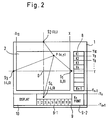
- a transparent glass panel 1 having a copiable area 2 in which an original 3 can be copied. If the original 3 is placed out of the copiable area 2, it cannot be copied.
- a designating area 4 is provided, having diagonals 5 and 5'.
- the reference numeral 6 designates a reference line along which the forward end of the original 3 is placed, and the reference numeral 7 designates an index which indicates the center line of an image to be reproduced as the origin (0, 0).
- An input panel 8 is located on the right side of the copying machine, through which various copying data and other necessary data are input.
- the input panel 8 is provided by printing on the top surface or the back surface of the glass panel 1. Necessary items are printed thereon.
- the input panel 8 can include several sections depending upon functions, such as sections A and B both for designating input points, sections C to F for designating treating modes, such as trimming, masking, centering, color designation, and section G for selecting color in accordance with the designation of a mode by the section F.
- sections A and B both for designating input points
- sections C to F for designating treating modes, such as trimming, masking, centering, color designation
- section G for selecting color in accordance with the designation of a mode by the section F.
- the glass panel 1 is additionally provided with reference scales 12 and 13 along the Y-axis and X-axis.
- Sensors S1 to S4 are directly stuck to the front surface or the back surface of the glass panel 1 at each corner. These sensors S1 to S4 are to detect touched points by sensing vibrations propagated from the touched point; more specifically, they detects the times for receiving signals.
- An original is placed on the glass panel 1 whereby a designated point 5 of the original is input as a position signal to the copying machine. In this way a copying area is designated.
- the position of a touched point can be calculated by reference to a reference point; for example, the index 7. In this way, it is possible to recognize whether it is a touched point entered in the input panel 8 or the copiable area 2.
- the input panel 8 enables the operator to identify the particular position in the input panel 8 to be input by touching.
- Step 1 An original 3 is placed in the copiable area 2 with the center line thereof aligned with the index 7 and with one edge thereof being alongside the reference line 6.
- Step 2 The start area in the section A is touched by a pen, and then a state is reached in which the position of the original 3 can be designated.
- the designated area 4 is set by touching the two points 5 and 5'. When a plurality of designated areas are to be set, the above-mentioned procedure is repeated.
- Step 3 When the designation is finished, the section B is touched so as to input the data obtained by Step 2 to the copying machine.
- Step 4 Various treating modes such as trimming, masking, centering, color designating, etc, are operable on the original 3 after the position is designated by the above-mentioned procedure. These modes can be input in the respective sections C to F.
- the original 3 is turned upside down on the copiable area 2.
- the turned original 3 is set by being placed alongside the reference line 6, and then the print switch on the copying machine is pressed. In this way the copying is carried out in an input mode.
- the sensors S1 to S4 are provided at the center of each side of the copiable area 2, slightly spaced outside the respective sides.
- Two input panels 8 and 9 are provided on two sides (in Figure 2, the lower and the right sides) by printing so as to enable an operator to input by key. These two input panels 8 and 9 are provided on the same glass panel 1.
- the sensors S1 and S3 are on the X-axis and the sensors S2 and S4 are on the Y-axis, so as to locate the origin (0, 0) at the center of the copiable area 2.
- the copying machine is equipped with an input section on the glass panel 1 through which required copying data are input, and a liquid crystal display section 10 is also provided. By touching the display, desired data can be input as displayed.
- the input panel 9 includes a sections 9-1 and 9-2 for inputting digital data and starting the copying operation, respectively.
- the sections 9-1 and 9-2 are printed on the glass panel 1.
- the input data are displayed on the liquid crystal display section 10.
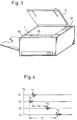
- Figure 3 is a perspective view showing a copying machine equipped with the input device shown in Figure 2, wherein a cover 11 is opened.
- the input device shown in Figure 2 is operated by touching a designated point P (X, Y) on the glass panel 1 with a pen or the like, the shock waves are propagated on the surface of the glass panel 1 or through it, and reach the respective sensors S1 to S4.
- the resulting timing chart is shown in the graph.
- t0 shows a time when a designated point is touched
- t1 to t4 show times when the sensors S1 to S4 detect the shock waves.
- T1 and T2 show time differences in detection between the sensors S1 and S3, and between the sensors S2 and S4.
- the sensors S1 to S4 convert the vibrations into electrical signals, and if this function is performed, any device such as piezo sensors, strain sensors, or mini-microphones can be used.
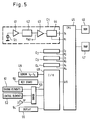
- the sensor S1 constitutes part of a detector circuit C1 which includes an amplifier 41, a filter 42, a comparator 43 and a latch 44.
- the vibrations detected by the sensor S1 are converted into electrical signals, and amplified into a predetermined voltage by the amplifier 41.
- the amplified voltage is trimmed by the filter 42 so as to remove unnecessary frequencies.
- the voltage is compared by the comparator 43 and when it reaches a predetermined value or exceeds it, it is detected as an effective signal, which is immediately sent to the latch 44.
- the time at which the effective signal comes out from the latch 44 is detected by a microcomputer (CPU) 45 which generates a reset signal R1, thereby holding the output of the latch 44.
- the circuit C1 is a detector circuit which comprises the arrangement from the sensor S1 to the latch 44.
- circuits C2 to C4 are detector circuits including the sensors S2 to S4, respectively.
- the CPU 45 is connected to a read-only memory (ROM) 46 which stores a required set of programs based on the data required to effect arithmetic calculation for identifying the designated point or points 4 and to execute the copying, the data being received from the input panels 8 and 9.
- the CPU 45 is also connected to a random access memory (RAM) 47 which temporarily stores the detected time of the sensors S1 to S4, the results of the arithmetic calculation for identifying the touched points, the copying data, and the copying state, an input/output port 48 which is used in increasing the number of input and output terminals and controlling same.
- RAM random access memory
- a sensor group 49 including sensors S5 to S x , a key board 50, several driving elements 51, several control elements 52, an aural transmitter 54, and a driver 53 for driving the driving elements 51, the control elements 52 and the aural transmitter 54, and a display device (the liquid crystal display section 10) 55 are connected to the input/output port 48.
- the CPU 45 outputs a signal which latches the latch 44 in the detection circuit C I only when the copying machine is “ready” but does not output when the coping machine is in operation or at a rise-up or warm-up time, herinafter called “rise-up", after it is switched on. During this period of time, even if the sensors S1 to S4 detect vibrations and the effective signals are output by the comparator 43, these signals are ignored. While the copying machine is at a rise-up time or in operation, the sensors S1 to S4 indiscriminately detect every vibration such as vibrations inherent to the copying machine which are caused by the rotation of the photosensitive drum and the operation of various driving mechanism. To avoid detecting unnecessary vibrations, it is devised so that the signal detected by the CPU 45 is detected only at the "ready” state, and found to be effective, and then the arithmetic operation is started so as to identify touched points.
- Any point P designated by touching is identified by arithmetic calculation in the following manner:
- the program for this arithmetic operation is stored in the ROM 46, wherein the arithmetic operation is conducted by calculating time differences (shown in Figure 4) in detecting vibrations by the sensors S1 to S4.
- the propagating speed of vibrations through the glass panel depends upon the material and the manufacturing method of the glass panel 1, normally 3,000 to 4,500 m/sec, and in soda glass, it is about 4,300 m/sec.
- Time difference T1 in signal reception between the sensors S1 and S3 on the X-axis is equal to a value obtained by dividing the linear distances from the point P to the sensors S1 and S3 by the speed v.
- This relationship is expressed by the following equation:
- time difference T2 in signal reception between the sensors S2 and S4 on the Y-axis is equal to a value obtained by dividing the linear distances from the point P to the sensors S1 and S3 by the speed v.
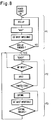
- the copying machine is switched on (start), and the rise-up or warm-up process starts at Flag F1, continuing until the copying machine comes into the "ready" state, where, for example, the fixing section is energized, the photosensitive drum is put into idle rotation (for electrical charging or discharging) and any other preparatory operations are performed (toward the "ready” state). During this period, "Wait” is displayed, and inputs of any touched point are ignored.
- Step 01 is possible to start only when the operation panel is ready to be operated; for example, the copying operation is ready. This corresponds to Flag F2 where a touched input is processed.
- a timer TM starts, which counts by 0.1 ⁇ sec so as to allow an error in the range of ⁇ 1 mm for identifying the position of a touched point.
- the tolerance is reduced to 1 mm or less. This allows a count unit of about 0.1 ⁇ sec.
- Step 02 decides whether or not an effective signal I1 comes from the sensor S1.
- This effective signal means a signla which is recognized by the CPU 45 when it is input from the latch 44 in the detection circuit C1 in Figure 5.
- Step 03 decides whether a detecting Flag F1 is on or not when the signal I1 is detected.
- Step 04 switches on Flag F1 upon detection of the signal I1, and the time of a timer TM is stored in a memory area M1 of the RAM 47 as a detecting time t1. Then, in order to fix the output of the latch 44 to "low", the output R1 of the CPU 45 is turned on.
- Steps 05 to 07 if the signal I1 is not detected at Step 02 or Flag F1 is already on at Step 03 or all proceses at Step 04 are finished, the sequence proceeds to Step 05.
- the time t2 of the sensor S2 is detected by the same procedures followed from Steps 02 to 04.
- Steps 08 to 13 the times t3 and t4 of the sensors S3 and S4 are detected by the same manner.
- Steps 14 judges Flags F1 to F4 as being on, if the detection of all the times t1 to t4 is finished from Steps 02 to 13, the sequence proceeds to Step 15. If any of the times t1 to t4 is not detected, the sequence returns to Step 20, and the time detecting program resumes from Steps 02 to 14.
- Step 15 turns on the aural transmitter 54 when the detection of all the times t1 to t4 are finished, thereby informing the operator of the completion of the signal inputs.
- the CPU 45 executes the process shown in the flowchart of Figure 7, and arithmetically processes the time t1 in accordance with the equations (3) and (4). Thus, the coordinate (x, y) of the point P designated by touching is obtained.
- Step 16 the time t3 stored in the RAM 47 is deducted from time t1, and a time difference T1 in detection between the sensors S1 and S3 on the X-axis is obtained, and the results are stored in a memory area M5 of the RAM 47.
- Step 17 a time difference T2 in detection between the sensors S2 and S4 on the Y-axis is obtained, and the results are stored in a memory area M6 of the RAM 47.
- Step 18 x is calculated by equation (3) and at Step 19 y is calculated by equation (4).
- Step 20 it is judged to decide which is earlier detected, the time t1 or t3. If the time t1 is earlier detected, the calculated value x is stored as a plus value in a memory area M x of the RAM 47. If the time t3 is earlier detected, the x is stored as a minus value in a memory area M x of the RAM 47.
- Step 23 decides which is earlier detected, the time t2 or t4. If the time t2 is earlier detected, at Step 25 the calculated value y is stored as a plus value in a memory area M y of the RAM 47. If the time t4 is earlier detected, at Step 25 the calculated value y is stored as a minus value in a memory area M y of the RAM 47.
- the coordinate (x, y) of the point P designated by touching is determined, and is stored in a memory area of the RAM 47.
- the position of the point P is identified on the glass panel 1 by reference to the program whereby the input comes from the input panels 8, 9 or from the copiable area 2.
- the last-mentioned determination is effected; for example, by setting the center of the copiable area 2 as the origin 0 (0, 0), and finding whether the touching occurs within the coordinates (-X10 to X10, -Y n-1 to Y10). If it is found to be from within these coordinate, it is judged that it comes from the copiable area 2.
- the input panels 8 and 9 are printed at places away from the copiable area 2, that is, right-ward of the sensor S1 (L ⁇ X10, where L is on the X-axis), and downward of the sensor S1 (-L ⁇ -Y n , where -L is on the Y-axis).
- the K1 to K n on the input panel 8 are input keys whereby copying data such as the designation of a designated area for an original and the selection of copying modes, are input, wherein the key K n is allotted to the operation of the copyings. Therefore, K1 can optionally allocated to regions Y10, and K2 is allocated to regions Y9 to Y8.
- the value 1 corresponds to a region -X2 to -X1
- the value 2 corresponds to a region -X1 to
- the value 3 corresponds to a region 0 to X1 and so on.
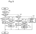
- Figure 9 shows a flowchart whereby it is judged which region in the RAM 47 the position calculated in Figure 7 belongs to, thereby finding whether the signal is input as a key input from the input panels 8 and 9 or else as a designation of area. Moreover, the input key is also identified in the memory.
- the value of the counter i is set to 1.
- This counter i shows an area within the input panel 8, and corresponds to the number of keys in the input panel 8.
- the counter has a range from 1 to n so as to correspond to the keys K1 to K n of the input panel 8 allotted to the coordinates Y10 to Y n .
- the ROM 46 reads the coordinates Y10 to Y n which correspond to the number of the counter i.
- Step 31 decides whether the M x on the X-axis for the detected point P is larger than the X10 stored in the ROM 46. If it is found to be larger, Step 32 decides whether the M y on the Y-axis is between the Y10 and Y9 stored in the ROM 46.
- Step 35 decides whether the counter i exceeds the number of keys. If it does not exceed it, the sequence returns to Step 32 where it is decided whether it is between Y9 and Y8. If it is between Y9 and Y8, Step 33 decides that it is key K2.
- Step 36 decides that an exact region has not been designated if the counter i exceeds, and displays "input again” through the display 55.
- Steps 37 to 42 shows a flowchart whereby it is detected that the ten-key key board 9-1 and the display 10 are designated. In the same manner as Steps 32 and 36 any of the keys KY1 to KY m has been designated.
- Step 43 if the values of M x and M y are found to be below X10 and Y10 at Steps 31 and 37, the coordinate (M x , M y ) of the point P designated by touching is displayed on the display 55 as numerals corresponding to the scales 13 and 14 printed along the glass panel 1, wherein the point P is evidently designated by touching in the copiable area 2. If two touched points are found, the rectangle having a diagonal as shown in Figure 1 is input as a signal area.
- the signal input device can per form level inputting, that is, input data about an image area of an original and other copying data to the copying machine from surface to surface.
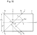
- Figure 10 shows a further example which is provided sensors S3 to S4 located adjacent to each end of the reference line 6 of the glass panel 1, which are bondaries of the copiable area), and S1 and S2 located at two apexes of a square with a side extending from S3 to S4 and arranged in a counter-clockwise direction.
- the origin is placed at the center of this square, and the OS1 is the X-axis, and OS2 is the Y-axis.
- a touched point P has the coordinate (x, y).
- the sensors in which they are arranged on the boundaries with an image area, so that they do not prevent the formation of an image.
- the sensors are located on the bondaries of the copiable area on the glass panel 1, precision is achieved.
Landscapes
- Engineering & Computer Science (AREA)
- Physics & Mathematics (AREA)
- General Engineering & Computer Science (AREA)
- Theoretical Computer Science (AREA)
- General Physics & Mathematics (AREA)
- Human Computer Interaction (AREA)
- Microelectronics & Electronic Packaging (AREA)
- Acoustics & Sound (AREA)
- Control Or Security For Electrophotography (AREA)
Applications Claiming Priority (4)
| Application Number | Priority Date | Filing Date | Title |
|---|---|---|---|
| JP23878890 | 1990-09-06 | ||
| JP238788/90 | 1990-09-06 | ||
| JP18865091A JP3111087B2 (ja) | 1990-09-06 | 1991-07-29 | 信号入力装置 |
| JP188650/91 | 1991-07-29 |
Publications (3)
| Publication Number | Publication Date |
|---|---|
| EP0474232A2 true EP0474232A2 (de) | 1992-03-11 |
| EP0474232A3 EP0474232A3 (en) | 1993-02-24 |
| EP0474232B1 EP0474232B1 (de) | 1996-04-24 |
Family
ID=26505055
Family Applications (1)
| Application Number | Title | Priority Date | Filing Date |
|---|---|---|---|
| EP91115018A Expired - Lifetime EP0474232B1 (de) | 1990-09-06 | 1991-09-05 | Durchsichtige berührungsempfindliche Eingabescheibe |
Country Status (4)
| Country | Link |
|---|---|
| US (1) | US5717432A (de) |
| EP (1) | EP0474232B1 (de) |
| JP (1) | JP3111087B2 (de) |
| DE (1) | DE69119001T2 (de) |
Cited By (7)
| Publication number | Priority date | Publication date | Assignee | Title |
|---|---|---|---|---|
| EP0561339A1 (de) * | 1992-03-17 | 1993-09-22 | Sharp Kabushiki Kaisha | Eingabegerät und Verfahren zu seiner Kalibrierung |
| FR2697935A1 (fr) * | 1992-11-12 | 1994-05-13 | Sextant Avionique | Terminal de communication compact et ergonomique muni de surfaces de détection de proximité. |
| WO2001043063A1 (en) * | 1999-12-06 | 2001-06-14 | Soundtouch Limited. | Inputting data |
| FR2841022A1 (fr) * | 2002-06-12 | 2003-12-19 | Centre Nat Rech Scient | Procede pour localiser un impact sur une surface et dispositif pour la mise en oeuvre de ce procede |
| WO2006039033A3 (en) * | 2004-10-01 | 2006-12-21 | 3M Innovative Properties Co | Vibration sensing touch input device |
| US7411581B2 (en) | 2002-02-06 | 2008-08-12 | Soundtouch Limited | Touch pad |
| EP3117879A1 (de) | 2015-07-14 | 2017-01-18 | Haute Ecole d'Ingénierie et de Gestion du Canton de Vaud (HEIG-VD) | Ballspielübungssystem |
Families Citing this family (27)
| Publication number | Priority date | Publication date | Assignee | Title |
|---|---|---|---|---|
| JPH09114591A (ja) * | 1995-10-12 | 1997-05-02 | Semiconductor Energy Lab Co Ltd | 液晶表示装置及びその表示方法 |
| JP3551591B2 (ja) * | 1995-12-27 | 2004-08-11 | 富士ゼロックス株式会社 | ペン入力装置 |
| JPH1091316A (ja) * | 1996-09-17 | 1998-04-10 | Sharp Corp | 座標入力装置及びそのためのプログラム記録媒体 |
| FR2755269B1 (fr) * | 1996-10-25 | 1998-12-04 | Asulab Sa | Dispositif d'identification d'une action manuelle sur une surface, notamment pour une piece d'horlogerie |
| JP3624070B2 (ja) * | 1997-03-07 | 2005-02-23 | キヤノン株式会社 | 座標入力装置及びその制御方法 |
| SE9800427D0 (sv) * | 1998-02-16 | 1998-02-16 | Lennart Christensson | Enkel inmatning för GPS-navigeringssystem |
| US7157649B2 (en) * | 1999-12-23 | 2007-01-02 | New Transducers Limited | Contact sensitive device |
| GB0116310D0 (en) * | 2001-07-04 | 2001-08-29 | New Transducers Ltd | Contact sensitive device |
| US6871149B2 (en) * | 2002-12-06 | 2005-03-22 | New Transducers Limited | Contact sensitive device |
| US7573466B1 (en) * | 2003-09-17 | 2009-08-11 | Rockwell Collins, Inc. | Method and apparatus for data entry for a liquid crystal display |
| US7309287B2 (en) * | 2003-12-10 | 2007-12-18 | Nintendo Co., Ltd. | Game machine having display screen with touch panel |
| US7578742B2 (en) * | 2004-03-26 | 2009-08-25 | Nintendo Co., Ltd. | Recording medium storing video game program and video game device |
| JP4574441B2 (ja) * | 2004-06-07 | 2010-11-04 | キヤノン株式会社 | 画像形成装置及びその制御方法 |
| US20060073891A1 (en) * | 2004-10-01 | 2006-04-06 | Holt Timothy M | Display with multiple user privacy |
| US20060139339A1 (en) * | 2004-12-29 | 2006-06-29 | Pechman Robert J | Touch location determination using vibration wave packet dispersion |
| US7499039B2 (en) * | 2005-01-10 | 2009-03-03 | 3M Innovative Properties Company | Iterative method for determining touch location |
| US7683890B2 (en) * | 2005-04-28 | 2010-03-23 | 3M Innovative Properties Company | Touch location determination using bending mode sensors and multiple detection techniques |
| ITTO20050569A1 (it) * | 2005-08-09 | 2007-02-10 | St Microelectronics Srl | Dispositivo e metodo di determinazione della posizione di contatto e dispositivo elettronico sensibile al contatto |
| WO2010024029A1 (ja) * | 2008-08-29 | 2010-03-04 | 日本電気株式会社 | コマンド入力装置および携帯用情報機器とコマンド入力方法 |
| US10185356B2 (en) | 2008-08-29 | 2019-01-22 | Nec Corporation | Information input device, information input method, and information input program |
| JP5407384B2 (ja) * | 2009-02-06 | 2014-02-05 | 富士ゼロックス株式会社 | 画像形成装置 |
| US8525784B2 (en) * | 2009-02-20 | 2013-09-03 | Seiko Epson Corporation | Input device for use with a display system |
| KR20120013969A (ko) * | 2009-04-06 | 2012-02-15 | 쓰리엠 이노베이티브 프로퍼티즈 컴파니 | 모듈형 감지 부품을 갖는 터치 센서 |
| TWI448931B (zh) * | 2009-10-16 | 2014-08-11 | Casio Computer Co Ltd | 指示位置檢測裝置及指示位置檢測方法 |
| JP5639489B2 (ja) * | 2011-01-25 | 2014-12-10 | キヤノン株式会社 | 情報処理装置及びその制御方法、プログラム、並びに記憶媒体 |
| JP2015089673A (ja) * | 2013-11-07 | 2015-05-11 | キヤノン株式会社 | 画像形成装置 |
| CA3054288C (en) | 2017-02-22 | 2024-11-12 | Beacon Street Innovations, Llc | REFRESHABLE BRAILLE DISPLAY UNIT |
Family Cites Families (11)
| Publication number | Priority date | Publication date | Assignee | Title |
|---|---|---|---|---|
| JPS62284419A (ja) * | 1986-05-31 | 1987-12-10 | Toshiba Corp | 入力装置 |
| JPS63182731A (ja) * | 1987-01-26 | 1988-07-28 | Canon Inc | 電子機器の入力装置 |
| JPH07121059B2 (ja) * | 1987-03-03 | 1995-12-20 | キヤノン株式会社 | 画像処理装置 |
| DE3809677A1 (de) * | 1987-03-19 | 1988-12-01 | Toshiba Kk | Anzeige- und eingabegeraet |
| JP2658039B2 (ja) * | 1987-03-20 | 1997-09-30 | キヤノン株式会社 | 情報処理装置 |
| JPS63244068A (ja) * | 1987-03-31 | 1988-10-11 | Canon Inc | デイジタイザ− |
| EP0297557B1 (de) * | 1987-07-01 | 1993-11-10 | Canon Kabushiki Kaisha | Koordinateneingabevorrichtung |
| JPH01114926A (ja) * | 1987-10-28 | 1989-05-08 | Canon Inc | 座標入力装置 |
| JP2522514B2 (ja) * | 1988-03-10 | 1996-08-07 | シャープ株式会社 | 操作入力装置 |
| US5070325A (en) * | 1988-03-18 | 1991-12-03 | Canon Kabushiki Kaisha | Coordinate input apparatus |
| US5049933A (en) * | 1989-01-27 | 1991-09-17 | Minolta Camera Kabushiki Kaisha | Image edit input device for use in copying machine |
-
1991
- 1991-07-29 JP JP18865091A patent/JP3111087B2/ja not_active Expired - Fee Related
- 1991-09-05 EP EP91115018A patent/EP0474232B1/de not_active Expired - Lifetime
- 1991-09-05 DE DE69119001T patent/DE69119001T2/de not_active Expired - Lifetime
-
1995
- 1995-01-20 US US08/376,066 patent/US5717432A/en not_active Expired - Lifetime
Cited By (18)
| Publication number | Priority date | Publication date | Assignee | Title |
|---|---|---|---|---|
| EP0561339A1 (de) * | 1992-03-17 | 1993-09-22 | Sharp Kabushiki Kaisha | Eingabegerät und Verfahren zu seiner Kalibrierung |
| FR2697935A1 (fr) * | 1992-11-12 | 1994-05-13 | Sextant Avionique | Terminal de communication compact et ergonomique muni de surfaces de détection de proximité. |
| EP0597753A1 (de) * | 1992-11-12 | 1994-05-18 | Sextant Avionique | Kompaktes, ergonomisches Kommunikationsendgerät, ausgestattet mit Flächen zur Näherungsdetektion |
| US5598527A (en) * | 1992-11-12 | 1997-01-28 | Sextant Avionique | Compact and ergonomic communications terminal equipped with proximity detection surfaces |
| US6891527B1 (en) | 1999-12-06 | 2005-05-10 | Soundtouch Limited | Processing signals to determine spatial positions |
| WO2001043063A1 (en) * | 1999-12-06 | 2001-06-14 | Soundtouch Limited. | Inputting data |
| US8436808B2 (en) | 1999-12-06 | 2013-05-07 | Elo Touch Solutions, Inc. | Processing signals to determine spatial positions |
| EP2267582A1 (de) | 2002-02-06 | 2010-12-29 | Soundtouch Limited | Touch pad |
| US7411581B2 (en) | 2002-02-06 | 2008-08-12 | Soundtouch Limited | Touch pad |
| US8319752B2 (en) | 2002-02-06 | 2012-11-27 | Elo Touch Solutions, Inc. | Touch pad |
| US7345677B2 (en) | 2002-06-12 | 2008-03-18 | Sensitive Object | Method for locating an impact on a surface and device therefor |
| US7511711B2 (en) | 2002-06-12 | 2009-03-31 | Sensitive Object | Method for locating an impact on a surface and device therefor |
| WO2003107261A3 (fr) * | 2002-06-12 | 2004-07-01 | Centre Nat Rech Scient | Procede pour localiser un impact sur une surface et dispositif pour la mise en oeuvre de ce procede |
| FR2841022A1 (fr) * | 2002-06-12 | 2003-12-19 | Centre Nat Rech Scient | Procede pour localiser un impact sur une surface et dispositif pour la mise en oeuvre de ce procede |
| WO2006039033A3 (en) * | 2004-10-01 | 2006-12-21 | 3M Innovative Properties Co | Vibration sensing touch input device |
| US8106888B2 (en) | 2004-10-01 | 2012-01-31 | 3M Innovative Properties Company | Vibration sensing touch input device |
| EP3117879A1 (de) | 2015-07-14 | 2017-01-18 | Haute Ecole d'Ingénierie et de Gestion du Canton de Vaud (HEIG-VD) | Ballspielübungssystem |
| WO2017009416A1 (en) | 2015-07-14 | 2017-01-19 | Haute Ecole D'ingenierie Et De Gestion Du Canton De Vaud (Heig-Vd) | Ball game training system |
Also Published As
| Publication number | Publication date |
|---|---|
| DE69119001D1 (de) | 1996-05-30 |
| JP3111087B2 (ja) | 2000-11-20 |
| EP0474232B1 (de) | 1996-04-24 |
| DE69119001T2 (de) | 1996-12-12 |
| JPH0511919A (ja) | 1993-01-22 |
| US5717432A (en) | 1998-02-10 |
| EP0474232A3 (en) | 1993-02-24 |
Similar Documents
| Publication | Publication Date | Title |
|---|---|---|
| EP0474232B1 (de) | Durchsichtige berührungsempfindliche Eingabescheibe | |
| EP1408397A2 (de) | Elektronisches Gerät | |
| EP0561339A1 (de) | Eingabegerät und Verfahren zu seiner Kalibrierung | |
| JPS63257020A (ja) | 画像処理装置 | |
| JP2574904B2 (ja) | 移動体用ナビゲーション装置 | |
| US5019865A (en) | Image processing apparatus wherein vibrations are used to designate a portion of an image to be reproduced | |
| EP0560260B1 (de) | Eingabegerät und Verfahren zur Dateneingabe | |
| JPH0991095A (ja) | 光学式タッチセンサ付き表示装置 | |
| JP2658048B2 (ja) | 情報入力装置 | |
| JPH05189126A (ja) | 打点入力装置 | |
| JP2621961B2 (ja) | 原稿検知装置 | |
| JP2736193B2 (ja) | 打点入力装置を具備した複写装置 | |
| JPH06102721A (ja) | 画像形成装置 | |
| KR920002717B1 (ko) | 복사기에 있어서 복사사용량 표시방법 및 회로 | |
| US7653223B2 (en) | Digital multifunction peripheral that has fingerprint reader capability | |
| JP2683357B2 (ja) | データ入力装置 | |
| JPH03264964A (ja) | 複写装置 | |
| JPH05307435A (ja) | 画像領域入力装置 | |
| KR970001279Y1 (ko) | 키포드/터치기 입력 동시 수용 모니터링장치 | |
| JPH03264965A (ja) | 複写装置 | |
| JPH03138633A (ja) | 画像形成装置 | |
| JPH0981304A (ja) | 画像処理装置 | |
| JPS5768870A (en) | Copying device | |
| JPH06102990A (ja) | 電子機器 | |
| JPS60146321A (ja) | 画像読取装置 |
Legal Events
| Date | Code | Title | Description |
|---|---|---|---|
| PUAI | Public reference made under article 153(3) epc to a published international application that has entered the european phase |
Free format text: ORIGINAL CODE: 0009012 |
|
| AK | Designated contracting states |
Kind code of ref document: A2 Designated state(s): DE FR GB |
|
| PUAL | Search report despatched |
Free format text: ORIGINAL CODE: 0009013 |
|
| AK | Designated contracting states |
Kind code of ref document: A3 Designated state(s): DE FR GB |
|
| 17P | Request for examination filed |
Effective date: 19930527 |
|
| K1C1 | Correction of patent application (title page) published |
Effective date: 19920311 |
|
| 17Q | First examination report despatched |
Effective date: 19941103 |
|
| GRAA | (expected) grant |
Free format text: ORIGINAL CODE: 0009210 |
|
| AK | Designated contracting states |
Kind code of ref document: B1 Designated state(s): DE FR GB |
|
| REF | Corresponds to: |
Ref document number: 69119001 Country of ref document: DE Date of ref document: 19960530 |
|
| ET | Fr: translation filed | ||
| PLBE | No opposition filed within time limit |
Free format text: ORIGINAL CODE: 0009261 |
|
| STAA | Information on the status of an ep patent application or granted ep patent |
Free format text: STATUS: NO OPPOSITION FILED WITHIN TIME LIMIT |
|
| 26N | No opposition filed | ||
| REG | Reference to a national code |
Ref country code: GB Ref legal event code: IF02 |
|
| PGFP | Annual fee paid to national office [announced via postgrant information from national office to epo] |
Ref country code: GB Payment date: 20090902 Year of fee payment: 19 |
|
| PGFP | Annual fee paid to national office [announced via postgrant information from national office to epo] |
Ref country code: DE Payment date: 20090903 Year of fee payment: 19 |
|
| PGFP | Annual fee paid to national office [announced via postgrant information from national office to epo] |
Ref country code: FR Payment date: 20091012 Year of fee payment: 19 |
|
| GBPC | Gb: european patent ceased through non-payment of renewal fee |
Effective date: 20100905 |
|
| REG | Reference to a national code |
Ref country code: FR Ref legal event code: ST Effective date: 20110531 |
|
| REG | Reference to a national code |
Ref country code: DE Ref legal event code: R119 Ref document number: 69119001 Country of ref document: DE Effective date: 20110401 |
|
| PG25 | Lapsed in a contracting state [announced via postgrant information from national office to epo] |
Ref country code: DE Free format text: LAPSE BECAUSE OF NON-PAYMENT OF DUE FEES Effective date: 20110401 Ref country code: FR Free format text: LAPSE BECAUSE OF NON-PAYMENT OF DUE FEES Effective date: 20100930 |
|
| PG25 | Lapsed in a contracting state [announced via postgrant information from national office to epo] |
Ref country code: GB Free format text: LAPSE BECAUSE OF NON-PAYMENT OF DUE FEES Effective date: 20100905 |