EP0465825A1 - Fenster- oder Türkonstruktion - Google Patents
Fenster- oder Türkonstruktion Download PDFInfo
- Publication number
- EP0465825A1 EP0465825A1 EP91109174A EP91109174A EP0465825A1 EP 0465825 A1 EP0465825 A1 EP 0465825A1 EP 91109174 A EP91109174 A EP 91109174A EP 91109174 A EP91109174 A EP 91109174A EP 0465825 A1 EP0465825 A1 EP 0465825A1
- Authority
- EP
- European Patent Office
- Prior art keywords
- holder
- window
- door construction
- construction according
- pane
- Prior art date
- Legal status (The legal status is an assumption and is not a legal conclusion. Google has not performed a legal analysis and makes no representation as to the accuracy of the status listed.)
- Granted
Links
- 238000010276 construction Methods 0.000 title claims abstract description 38
- 230000001154 acute effect Effects 0.000 claims abstract description 3
- 238000003780 insertion Methods 0.000 claims abstract description 3
- 230000037431 insertion Effects 0.000 claims abstract description 3
- 239000011521 glass Substances 0.000 claims description 20
- 239000002184 metal Substances 0.000 claims description 5
- 239000002023 wood Substances 0.000 claims description 2
- 238000004904 shortening Methods 0.000 claims 1
- 230000002787 reinforcement Effects 0.000 description 3
- 239000013464 silicone adhesive Substances 0.000 description 3
- XLYOFNOQVPJJNP-UHFFFAOYSA-N water Substances O XLYOFNOQVPJJNP-UHFFFAOYSA-N 0.000 description 3
- 238000004519 manufacturing process Methods 0.000 description 2
- 230000003014 reinforcing effect Effects 0.000 description 2
- 125000006850 spacer group Chemical group 0.000 description 2
- 241000047428 Halter Species 0.000 description 1
- 239000000463 material Substances 0.000 description 1
- 230000003287 optical effect Effects 0.000 description 1
- 230000036316 preload Effects 0.000 description 1
- 230000001681 protective effect Effects 0.000 description 1
- 230000000007 visual effect Effects 0.000 description 1
Images


Classifications
-
- E—FIXED CONSTRUCTIONS
- E06—DOORS, WINDOWS, SHUTTERS, OR ROLLER BLINDS IN GENERAL; LADDERS
- E06B—FIXED OR MOVABLE CLOSURES FOR OPENINGS IN BUILDINGS, VEHICLES, FENCES OR LIKE ENCLOSURES IN GENERAL, e.g. DOORS, WINDOWS, BLINDS, GATES
- E06B3/00—Window sashes, door leaves, or like elements for closing wall or like openings; Layout of fixed or moving closures, e.g. windows in wall or like openings; Features of rigidly-mounted outer frames relating to the mounting of wing frames
- E06B3/66—Units comprising two or more parallel glass or like panes permanently secured together
- E06B3/6617—Units comprising two or more parallel glass or like panes permanently secured together one of the panes being larger than another
-
- E—FIXED CONSTRUCTIONS
- E06—DOORS, WINDOWS, SHUTTERS, OR ROLLER BLINDS IN GENERAL; LADDERS
- E06B—FIXED OR MOVABLE CLOSURES FOR OPENINGS IN BUILDINGS, VEHICLES, FENCES OR LIKE ENCLOSURES IN GENERAL, e.g. DOORS, WINDOWS, BLINDS, GATES
- E06B3/00—Window sashes, door leaves, or like elements for closing wall or like openings; Layout of fixed or moving closures, e.g. windows in wall or like openings; Features of rigidly-mounted outer frames relating to the mounting of wing frames
- E06B3/30—Coverings, e.g. protecting against weather, for decorative purposes
- E06B3/308—Wing frames covered on the outside by a rigidly-mounted outer frame
-
- E—FIXED CONSTRUCTIONS
- E06—DOORS, WINDOWS, SHUTTERS, OR ROLLER BLINDS IN GENERAL; LADDERS
- E06B—FIXED OR MOVABLE CLOSURES FOR OPENINGS IN BUILDINGS, VEHICLES, FENCES OR LIKE ENCLOSURES IN GENERAL, e.g. DOORS, WINDOWS, BLINDS, GATES
- E06B3/00—Window sashes, door leaves, or like elements for closing wall or like openings; Layout of fixed or moving closures, e.g. windows in wall or like openings; Features of rigidly-mounted outer frames relating to the mounting of wing frames
- E06B3/54—Fixing of glass panes or like plates
- E06B3/58—Fixing of glass panes or like plates by means of borders, cleats, or the like
- E06B3/585—Fixing of glass panes or like plates by means of borders, cleats, or the like adjustable, e.g. for accommodating panes of various thickness, or with provisions for altering the clamping force on the pane
- E06B3/5857—Fixing of glass panes or like plates by means of borders, cleats, or the like adjustable, e.g. for accommodating panes of various thickness, or with provisions for altering the clamping force on the pane the fixing being adjustable, e.g. in one of several possible positions
-
- E—FIXED CONSTRUCTIONS
- E06—DOORS, WINDOWS, SHUTTERS, OR ROLLER BLINDS IN GENERAL; LADDERS
- E06B—FIXED OR MOVABLE CLOSURES FOR OPENINGS IN BUILDINGS, VEHICLES, FENCES OR LIKE ENCLOSURES IN GENERAL, e.g. DOORS, WINDOWS, BLINDS, GATES
- E06B7/00—Special arrangements or measures in connection with doors or windows
- E06B7/16—Sealing arrangements on wings or parts co-operating with the wings
- E06B7/22—Sealing arrangements on wings or parts co-operating with the wings by means of elastic edgings, e.g. elastic rubber tubes; by means of resilient edgings, e.g. felt or plush strips, resilient metal strips
- E06B7/23—Plastic, sponge rubber, or like strips or tubes
- E06B7/2305—Plastic, sponge rubber, or like strips or tubes with an integrally formed part for fixing the edging
- E06B7/2307—Plastic, sponge rubber, or like strips or tubes with an integrally formed part for fixing the edging with a single sealing-line or -plane between the wing and the part co-operating with the wing
- E06B7/231—Plastic, sponge rubber, or like strips or tubes with an integrally formed part for fixing the edging with a single sealing-line or -plane between the wing and the part co-operating with the wing with a solid sealing part
-
- E—FIXED CONSTRUCTIONS
- E06—DOORS, WINDOWS, SHUTTERS, OR ROLLER BLINDS IN GENERAL; LADDERS
- E06B—FIXED OR MOVABLE CLOSURES FOR OPENINGS IN BUILDINGS, VEHICLES, FENCES OR LIKE ENCLOSURES IN GENERAL, e.g. DOORS, WINDOWS, BLINDS, GATES
- E06B7/00—Special arrangements or measures in connection with doors or windows
- E06B7/16—Sealing arrangements on wings or parts co-operating with the wings
- E06B7/22—Sealing arrangements on wings or parts co-operating with the wings by means of elastic edgings, e.g. elastic rubber tubes; by means of resilient edgings, e.g. felt or plush strips, resilient metal strips
- E06B7/23—Plastic, sponge rubber, or like strips or tubes
- E06B7/2305—Plastic, sponge rubber, or like strips or tubes with an integrally formed part for fixing the edging
- E06B7/2312—Plastic, sponge rubber, or like strips or tubes with an integrally formed part for fixing the edging with two or more sealing-lines or -planes between the wing and part co-operating with the wing
-
- E—FIXED CONSTRUCTIONS
- E06—DOORS, WINDOWS, SHUTTERS, OR ROLLER BLINDS IN GENERAL; LADDERS
- E06B—FIXED OR MOVABLE CLOSURES FOR OPENINGS IN BUILDINGS, VEHICLES, FENCES OR LIKE ENCLOSURES IN GENERAL, e.g. DOORS, WINDOWS, BLINDS, GATES
- E06B3/00—Window sashes, door leaves, or like elements for closing wall or like openings; Layout of fixed or moving closures, e.g. windows in wall or like openings; Features of rigidly-mounted outer frames relating to the mounting of wing frames
- E06B3/70—Door leaves
- E06B3/72—Door leaves consisting of frame and panels, e.g. of raised panel type
- E06B3/721—Door leaves consisting of frame and panels, e.g. of raised panel type with panels on one lateral side of the frame only
Definitions
- the invention relates to a window or door construction with a multi-pane glazing arranged in a casement or stick frame, at least the casement being formed by an inner load-bearing casement profile with a bearing flange on the room side and a receiving groove for a substantially U-shaped profile comprising the multicore glazing in the outer edge region -shaped holder.
- a construction of the generic type is known from DE utility model 85 05 873.
- an insulating glass pane is held on a sash frame profile by means of an essentially U-shaped holder, the holder engaging with its leg on the room side in a receiving groove of the sash frame profile.
- the tension between the outer leg of the holder and the room-side abutment leg of the airfoil is achieved by means of a circumferential elastic strip which is supported against the room-side surface of the inner pane of the multi-pane glazing.
- the holder Since the holder has to span the entire cross-sectional width of the multi-pane glazing and the elastic strip and engages in a groove protruding into the wing profile on the room side, the web of the holder is inevitably relatively long. Furthermore, since the forces acting on the pane and the weight of the pane have to be removed via the web of the holder, a support flange on the wing profile is required, which at least partially engages and supports the holder in the web area.
- the multi-pane glazing cannot be held securely. Due to tolerances in the pane area, it can happen that the elastic strip does not produce a uniform, circumferential contact pressure. In addition, because of the length of the holder web and because of the constructive solution of the direct transfer of the forces into the web, no secure hold of the disk is guaranteed. For this reason, the construction also provides for an additional mounting of the pane over the frame, which at least overlaps the outer pane in the edge area over the same depth as the holder and exerts a compressive force on this and the outer pane, so that the pane is in the closed state of the Wing is also held.
- a secure fit of the insulating glass pane is also not guaranteed because tolerances occur during the pane production which, in the construction described above, would have to be accommodated solely by the seal lying against the inner pane surface. If additional suction and pressure forces are exerted on the pane due to the influence of wind, then there are inevitably leaks in the edge area of the holder and in the area of the elastic seal, so that moisture can penetrate, for which no drainage device in the known construction is provided.
- the invention is therefore based on the object of improving a window or door construction of the generic type in such a way that the structure is simplified, the mounting of the multi-pane glazing is improved both in the closed and in the open state of a wing and a suitable load transfer is made possible.
- a suitable design of the pane holder in the casement or stick frame is intended to enable improved drainage at the same time.
- the outer leg of the holder comprising the multi-pane glazing is arranged at an acute angle and the inner, space-side leg of the holder is at an obtuse angle to the web of the holder connecting them and that the receiving groove of the wing profile is one for positive locking Inclusion of the leg on the room side has the corresponding design and arrangement. So that the edge of the outer glass pane is not gripped too far for optical reasons, but is only held by the holder and protected in the edge area, the outer leg of the holder has approximately half the length and thickness of the inner leg of the holder with which the holder in engages the receiving groove of the casement profile.
- the web of the holder can be increasingly reinforced on the room side, so that any forces which may have been introduced into the holder can be dissipated well into the frame profile.
- the parallel leg surfaces of the holder can be roughened or toothed, for example, while the corresponding groove surfaces are machined accordingly, so that the holder is securely held or locked when the inner leg is pressed into the receiving groove.
- the receiving groove is longer than the inner leg of the holder and has an enlarged cross-section at its end, so that there is a sufficiently large space for receiving the end of the holder and tolerances can be compensated for.
- the holder can advantageously encompass the multi-pane glazing all around if it is made of plastic, for example, or at least attack on the four corners of the multi-pane glazing in the form of short pieces if it is made of metal, for example, since the material and shape make it sufficient sufficient inherent stability can be achieved.
- drainage bores or relaxation bores are provided at a distance from one another in the web area, for example for steam pressure compensation, the width of which can extend essentially over the entire rebate area.
- the holder and the sash profile are advantageously arranged such that the web of the holder with a sash wall is substantially in the same plane and forms a wall of the fitting chamber.
- either the holder can have a stop which engages into the fitting chamber, against which a center seal comes to rest in the closed state of the sash, or this stop can be provided on the fitting chamber wall of the sash frame.
- the holder can be used in a window or door construction in which multi-pane glazing is used, which is formed by a step insulating glass pane.
- the wing profile in order to shorten the holder in the web area, can be extended into the rebate space below the inner, shortened pane of the stepped glass.
- the wing profile can have at least one shoulder on the section protruding into the rebate space, on which the load of the multi-pane glazing can be removed.
- the wind forces acting on the pane like the weight of the pane, are therefore essentially diverted into the shoulder area of the casement, so that the holder alone takes on its protective and holding function in the area of the outer pane edge.
- the outer, elongated pane of the stepped glass forms an end stop for the insertion path of the holder when the holder is inserted with its inner leg into the receiving groove.
- the construction described above has the further advantage that a deepest rebate space is formed between the outer edge of the outer pane and the space-side contact leg of the sash frame in the area of the fitting chamber, in which any water that may have penetrated can accumulate in order to pass through the holder provided drainage holes in the drainage chamber and from there to be derived in a conventional manner.
- the drainage holes made possible by the gradation of the casement and the stepped glass at the lowest point of the pane ensure that water is drained off even if a holder that runs across the entire width of the pane and engages in the casement profile is not horizontal and level.
- the section of the wooden profile protruding into the rebate space is reinforced by a metal fitting or that the receiving groove is provided in the metal fitting in order to ensure a secure hold of the holder. It is also conceivable here to extend the holder by means of a web projecting into the fitting chamber, which at the same time acts as an additional fastening of the holder to the wooden wing and as a stop for the center seal.
- the glazing has a wing 1 and a fixed glazing 2.
- the fixed glazing consists of a conventional multi-pane glazing 3, which is received between an outer seal 4 and an inner seal 5.
- the outer seal 4 is held in the leg of an outer frame profile 6, while the inner seal 5 is held by means of a glass strip 7, which is supported on an inner frame profile 8.
- the outer frame profile 6 and the inner frame profile 8 are connected to one another by means of an insulating bridge 9.
- the multi-pane glazing of the wing 1 is formed by a step insulating glass pane 10. It can be seen that the inner disc 11 against is shortened above the outer disc 12, so that there is a step that enables the sash profile part 13 to engage with a shoulder 14 in the rebate space 15 and thus engages under the shortened inner disc 11.
- the forces that act on the pane in the vertical and horizontal directions can thus be dissipated in the sash frame part 13 via the shoulder 14 in the vertical direction and via the spacer 16 and the silicone adhesive 17.
- a receiving groove 18 is provided, into which a holder 19 engages with its inner leg 20. With its outer leg 21, the holder 19 engages around the edge region of the outer pane 12, so that it is protected against damage and at the same time is held on the sash profile part 13.
- the holder 19 is shown on an enlarged scale. It can be seen that the outer flange 21 is shortened and narrower than the inner flange 20 and that the web 22 connecting the flanges of the holder has an increasing reinforcement in the direction of the sash profile part 13. The outer flange 21 is slightly inclined inward when the holder is not installed, so that a corresponding preload is generated when the holder is installed.
- the inclination of the inner leg 20 has the advantage that the holder can be easily inserted into the receiving groove 18 because the free end of the inclined leg in the mouth region of the groove enables the outer leg 21 to be at a certain distance from the outer glass pane 12 and only then comes into contact with them when the holder 19 is snapped into the groove and pushed into it as far as possible. If the holder is pushed increasingly into the receiving groove 18, then the outer leg 21 is pressed outward against its own prestressing force, so that the pane is pressed against the spacer 16 and the silicone adhesive 17 or, instead of the silicone adhesive, against a profile element with increasing contact pressure.
- the oblique arrangement of the inner leg 20 thus has the advantage that the insulating glass pane can be held securely on the casement profile part 13 despite manufacturing tolerances.
- the inwardly increasing reinforcement of the web 22 has the advantage that the holder has an increased inherent stability and, in particular in the case of glazing according to FIG. 3, that is to say with an extended web 22, receives additional prestressing against the edge of the pane.
- flanks of the receiving groove 18 or the inner leg 20 of the holder 19 have parallel leg surfaces so that the holder can be pushed further into the groove according to the tolerances of the insulating glass pane, with a greater clamping force of the outer leg 21 against by pushing deeper into the groove the outer disc 12 is achieved.
- a toothing 23 is preferably provided in the embodiment shown, which can engage with a corresponding toothing in the receiving groove 18 so that the holder 19 remains in its pressed-in position.
- the holder 19 has drainage holes 24 and, if appropriate, additional relief holes for vapor pressure compensation, which are arranged at a distance from one another when the holder rotates.
- the diameter of a bore 24 or the width of an opening, e.g. an elongated hole opening, the width of the rebate space 15 between the inner surface of the outer pane 12 and the end face facing the rebate space of the leg of the wing frame profile part 13 delimiting the receiving groove 18 may correspond.
- the drainage opening 24 is arranged at the deepest point of the rebate space 15, so that the condensed water can be drained into the drainage chamber 25 and from there in a manner known per se.
- a seal 26 is provided, which in the closed state rests against the outside of the outer pane 12 and thereby overlaps the outer leg 21 of the holder 19, so that in the closed state of the wing 1 there is no visual difference to the design of the fixed glazing 2 is recognizable.
- the holder 28 has a corresponding flange construction, so that reference can be made to the above description in this connection. It also has a stop 30 which engages in the fitting chamber 29 and comes to bear against a central seal 31 when the sash is closed.
- the holder 19, 28 is essentially in one plane with the section of the sash frame section 13 or 32 facing the fitting chamber 29 and together with the sash section section Boundary wall for the fitting chamber 29 forms.
- FIGS. 4 and 5 show fixed glazing with one-sided and two-sided arrangement of stepped insulating glass panes, which, as so-called structural glazing, are held only by holders 33, 34 and 35 on corresponding stick frame profiles 36 and 37, which are held in corresponding shoulder sections 38, 39, Have 40 grooves of the type shown in Fig. 1.
- wooden wings 41 and 42 and wooden rungs 43 and 44 are shown.
- the wooden wing 41 has a receiving groove 45, in which the inner leg 46 of a holder 47 is inserted.
- a reinforcement angle 49 is provided, which e.g. can be nailed or screwed onto the shoulder.
- the wooden wing 42 is equipped with a reinforcing strip 50 which has a flange portion 53 which projects into the rebate space 51 of the step insulating glass pane 52 and which delimits a receiving groove 55 in the vertical leg 54 of the reinforcing strip 50 in which the inner flange 56 of a holder 57 is received.
- the leg 54 also serves as a stop for the center seal.
- FIG. 8 shows a so-called wooden sash 58 which has a wooden wing 59 and a wooden wing 60.
- the wooden wing 60 can remain as a rung, while the wooden wing 59 is swung open.
- the holder 61 has, for the purpose of additional fastening, a web 62 reaching downwards, which also serves as a stop for the center seal.
- wing construction according to the invention can, due to the advantageous configuration of the holder, be used in standard and system-compliant, commercially available profile systems with small glass rebate heights of approximately 20 to 26 mm.
- an existing system can be supplemented by the construction according to the invention without the system program being restricted in its variability.
- Fig.1 shows a variant with wing and fixed glazing with a uniform external appearance. It can be clearly seen that the fixed glazing does not require an extended leg of the frame 6 compared to the existing optimized system program.
Landscapes
- Engineering & Computer Science (AREA)
- Civil Engineering (AREA)
- Structural Engineering (AREA)
- Securing Of Glass Panes Or The Like (AREA)
- Liquid Crystal (AREA)
- Non-Silver Salt Photosensitive Materials And Non-Silver Salt Photography (AREA)
- Special Wing (AREA)
Abstract
Description
- Die Erfindung betrifft eine Fenster- oder Türkonstruktion mit einer in einem Flügelrahmen oder Stockrahmen angeordneten Mehrscheibenverglasung, wobei wenigstens der Flügelrahmen von einem inneren tragenden Flügelprofil mit einem raumseitigen Anlageflansch gebildet ist und eine Aufnahmenut für einen die Mehrscheibenverglasung im äußeren Randbereich umfassenden, im wesentlichen U-Profil-förmigen Halter aufweist.
- Eine Konstruktion der gattungsgemäßen Art ist durch die DE-Gebrauchsmusterschrift85 05 873 bekannt geworden. Bei dieser Konstruktion wird eine Isolierglasscheibe mittels eines im wesentlichen U-förmig ausgebildeten Halters an einem Flügelrahmenprofil gehalten, wobei der Halter mit seinem raumseitigen Schenkel in eine Aufnahmenut des Flügelrahmenprofils eingreift. Die Spannung zwischen dem äußeren Schenkel des Halters und dem raumseitigen Anlageschenkel des Flügelprofils wird mittels einer umlaufenden elastischen Leiste erzielt, die sich gegen die raumseitige Fläche der inneren Scheibe der Mehrscheibenverglasung abstützt. Da der Halter die gesamte Querschnittsbreite der Mehrscheibenverglasung und der elastischen Leiste übergreifen muß und in eine raumseitig in das Flügelprofil hineinragende Nut eingreift, ist der Steg des Halters zwangsläufig verhältnismäßig lang ausgebildet. Da ferner die an der Scheibe angreifenden Kräfte und das Gewicht der Scheibe über den Steg des Halters abgetragen werden müssen, ist ein Abstützflansch am Flügelprofil erforderlich, welcher den Halter im Stegbereich wenigstens teilweise untergreift und abstützt.
- Trotz der zusätzlichen Abstützung ist ein sicherer Halt der Mehrfachscheibenverglasung nicht gewährleistet. Durch im Scheibenbereich liegende Toleranzen kann es vorkommen, daß die elastische Leiste keinen gleichmäßigen, umlaufenden Anpreßdruck erzeugt. Darüberhinaus ist wegen der Länge des Haltersteges sowie wegen der konstruktiven Lösung der unmittelbaren Abtragung der Kräfte in den Steg kein sicherer Halt der Scheibe gewährleistet. Aus diesem Grunde sieht die Konstruktion auch eine zusätzliche Halterung der Scheibe über den Blendrahmen vor, der mindestens die äußere Scheibe im Randbereich über die gleiche Tiefe übergreift wie der Halter und auf diesen sowie die äußere Scheibe eine Druckkraft ausübt, so daß die Scheibe im Schließzustand des Flügels zusätzlich gehalten wird.
- Ein sicherer Sitz der Isolierglasscheibe ist auch deswegen nicht gewährleistet, weil bei der Scheibenherstellung Toleranzen auftreten, die bei der vorbeschriebenen Konstruktion allein durch die gegen die innere Scheibenfläche anliegende Dichtung aufgenommen werden müßten. Wenn nun noch zusätzliche Sog- und Druckkräfte auf die Scheibe infolge von Windeinfluß ausgeübt werden, dann kommt es zwangsläufig zu Undichtigkeiten im Randbereich des Halters und im Bereich der elastischen Dichtung, so daß Feuchtigkeit eindringen kann, für die bei der bekannten Konstruktion darüber hinaus keine Entwässerungseinrichtung vorgesehen ist.
- Der Erfindung liegt daher die Aufgabe zugrunde, eine Fenster- oder Türkonstruktion der gattungsgemäßen Art dahingehend zu verbessern, daß der Aufbau vereinfacht, die Halterung der Mehrscheibenverglasung sowohl im geschlossenen als auch im geöffneten Zustand eines Flügels verbessert und eine geeignete Lastabtragung ermöglicht werden. Durch eine geeignete Gestaltung der Scheibenhalterung im Flügel- bzw. Stockrahmen soll gleichzeitig eine verbesserte Entwässerung ermöglicht werden.
- Die Aufgabe wird gemäß der Erfindung dadurch gelöst, daß der äußere Schenkel des die Mehrscheibenverglasung umfassenden Halters im spitzen Winkel und der innere, raumseitige Schenkel des Halters im stumpfen Winkel zu dem sie verbindenden Steg des Halters angeordnet sind und daß die Aufnahmenut des Flügelprofils eine zur formschlüssigen Aufnahme des raumseitigen Schenkels korrespondierende Ausbildung und Anordnung aufweist. Damit der Rand der äußeren Glasscheibe aus optischen Gründen nicht zu weit umgriffen wird, sondern von dem Halter nur gehalten und im Randbereich geschützt wird, besitzt der äußere Schenkel des Halters etwa die halbe Länge und Stärke des inneren Schenkels des Halters, mit welchem der Halter in die Aufnahmenut des Flügelrahmenprofils eingreift. Der Steg des Halters kann raumseitig zunehmend verstärkt sein, so daß durch die Scheibe in den Halter möglicherweise eingeleitete Kräfte gut in das Rahmenprofil abgeleitet werden. Im Bereich der Eingriffsfläche des schräg verlaufenden inneren Schenkels können die parallelen Schenkelflächen des Halters aufgerauht oder beispielsweise verzahnt sein, während die korrespondierenden Nutenflächen entsprechend bearbeitet sind, so daß ein sicherer Halt bzw. eine Verrastung des Halters beim Eindrücken des inneren Schenkels in die Aufnahmenut erfolgt. Die Aufnahmenut ist länger ausgebildet als der innere Schenkel des Halters und besitzt an ihrem Ende einen vergrößerten Querschnitt, so daß ein genügend großer Raum zur Aufnahme des Halterendes vorhanden ist und Toleranzen ausgeglichen werden können.
- Der Halter kann vorteilhaft die Mehrscheibenverglasung umlaufend umgreifen, wenn er beispielsweise aus Kunststoff hergestellt ist, oder wenigstens an den vier Ecken der Mehrscheibenverglasung in Form von Kurzstücken angreifen, wenn er beispielsweise aus Metall hergestellt ist, da durch das Material und die Formgebung eine genügende Eigenstabilität erzielt werden kann. Bei einem umlaufend ausgebildeten Halter sind im Stegbereich im Abstand zueinander angeordnete Entwässerungsbohrungen oder Entspannungsbohrungen z.B. für Dampfdruckausgleich vorgesehen, wobei diese sich in ihrer Breite im wesentlichen über den gesamten Falzraum erstrecken können. Der Halter und das Flügelrahmenprofil sind vorteilhaft derart angeordnet, daß der Steg des Halters mit einer Flügelrahmenwand im wesentlichen in der gleichen Ebene liegt und eine Wand der Beschlagskammer bildet. wodurch eine möglichst geringe abzudeckende Beschlagskammertiefe, bezogen auf die Blendrahmenkante, erreicht wird. Dabei kann entweder der Halter einen in die Beschlagskammer hineingreifenden Anschlag aufweisen, gegen den im Schließzustand des Flügels eine Mitteldichtung zur Anlage kommt, oder dieser Anschlag kann an der Beschlagskammerwand des Flügelrahmens vorgesehen sein.
- In besonders vorteilhafter Weise ist der Halter bei einer Fenster- oder Türkonstruktion einsetzbar, bei welcher eine Mehrscheibenverglasung zum Einsatz kommt, die von einer Stufenisolierglasscheibe gebildet ist. In diesem Falle kann zur Erzielung einer Verkürzung des Halters im Stegbereich das Flügelprofil bis unter die innere, verkürzte Scheibe des Stufenglases in den Falzraum hinein verlängert sein. Dabei kann das Flügelprofil an dem in den Falzraum hineinragenden Abschnitt wenigstens eine Schulter aufweisen, auf welcher die Last der Mehrscheibenverglasung abtragbar ist. Die an der Scheibe angreifenden Windkräfte werden daher ebenso wie das Gewicht der Scheibe im wesentlichen in den Schulterbereich des Flügelrahmens abgeleitet, so daß der Halter allein seine Schutz-und Haltefunktion im Bereich des äußeren Scheibenrandes übernimmt. Die äußere, verlängerte Scheibe des Stufenglases bildet für den Einschubweg des Halters einen stirnseitigen Begrenzungsanschlag, wenn der Halter mit seinem inneren Schenkel in die Aufnahmenut eingeführt wird.
- Die vorbeschriebene Konstruktion hat den weiteren Vorteil, daß zwischen dem äußeren Rand der äußeren Scheibe und der raumseitigen, im Bereich der Beschlagskammer liegenden Anlageschenkel des Flügelrahmens ein tiefster Falzraum gebildet wird, in welchem sich ggf. eingedrungenes Wasser ansammeln kann, um über die in dem Halter vorgesehenen Entwässerungsbohrungen in die Entwässerungskammer und von dort in an sich bekannter Weise abgeleitet zu werden.
- Durch die infolge der Abstufung des Flügelrahmens und durch das Stufenglas an der tiefsten Stelle der Scheibe ermöglichten Entwässerungsbohrungen wird selbst dann ein Ableiten von Wasser sichergestellt, wenn ein über die gesamte Breite der Glasscheibe verlaufender und in das Flügelrahmenprofil eingreifender Halter nicht horizontal und eben ausgebildet ist.
- Bei der Verwendung einer Holzkonstruktion als Flügelrahmenprofil ist vorteilhaft vorgesehen, daß der in den Falzraum hineinragende Abschnitt des Holzprofils durch einen Metallbeschlag verstärkt ist bzw. daß die Aufnahmenut in dem Metallbeschlag vorgesehen ist, um einen sicheren Halt des Halters zu gewährleisten. Es ist auch hier denkbar, den Halter durch einen in die Beschlagskammer hineinragenden Steg zu verlängern, welcher gleichzeitig als zusätzliche Befestigung des Halters an dem Holzflügel und als Anschlag für die Mitteldichtung wirkt.
- Weitere Merkmale, Einzelheiten und Vorteile ergeben sich aus der nachfolgenden, Beschreibung von bevorzugten Ausführungsbeispielen anhand der Zeichnung. Darin zeigen:
- Fig. 1 einen schematischen Vertikalschnitt durch eine kombinierte Flügel-und Festverglasung eines Fensters gemäß der Erfindung, wobei eine Stufenisolierglasscheibe im Flügelbereich zum Einsatz kommt;
- Fig. 2 eine vergrößerte Schnittdarstellung des in der Fig. 1 im Einbauzustand gezeigten Halters;
- Fig. 3 eine weitere Ausführungsform der erfindungsgemäßen Fensterkonstruktion mit einer herkömmlichen Mehrscheibenverglasung;
- Fig.4 u.5 einseitige und zweiseitige Festverglasungen;
- Fig. 6 u.7 weitere Ausführungsbeispiele, bei denen die Flügel- und Stockrahmenprofile aus Holz hergestellt sind;
- Fig. 8 einen Stulpflügel mit Holzflügelrahmenprofilen, und
- Fig. 9 ein weiteres Ausführungsbeispiel für einen Stulpflügel.
- Bei der in der Fig. 1 dargestellten erfindungsgemäßen Konstruktion weist die Verglasung einen Flügel 1 und eine Festverglasung 2 auf. Die Festverglasung besteht aus einer herkömmlichen Mehrscheibenverglasung 3, die zwischen einer äußeren Dichtung 4 und einer inneren Dichtung 5 aufgenommen wird. Die äußere Dichtung 4 ist im Schenkel eines äußeren Blendrahmenprofils 6 gehalten, während die innere Dichtung 5 mittels einer Glasleiste 7 gehalten wird, welche sich auf einem inneren Blendrahmenprofil 8 abstützt. Das äußere Blendrahmenprofil 6 und das innere Blendrahmenprofil 8 sind mittels einer Isolierbrücke 9 miteinander verbunden.
- Die Mehrscheibenverglasung des Flügels 1 ist von einer Stufenisolierglasscheibe 10 gebildet. Es ist zu erkennen, daß die innere Scheibe 11 gegenüber der äußeren Scheibe 12 verkürzt ausgebildet ist, so daß sich eine Stufe ergibt, die es ermöglicht, daß das Flügelrahmenprofilteil 13 mit einer Schulter 14 in den Falzraum 15 eingreifen kann und damit die verkürzte innere Scheibe 11 untergreift. Die Kräfte, die an der Scheibe in vertikaler und horizontaler Richtung angreifen, können dadurch über die Schulter 14 in vertikaler Richtung und über den Abstandshalter 16 sowie die Silikonverklebung 17 in das Flügelrahmenprofilteil 13 abgeleitet werden.
- In dem Schulterbereich 14 des Flügelrahmenprofils 13 ist eine Aufnahmenut 18 vorgesehen, in welche ein Halter 19 mit seinem inneren Schenkel 20 eingreift. Der Halter 19 umgreift mit seinem äußeren Schenkel 21 den Randbereich der äußeren Scheibe 12, so daß diese vor Beschädigungen geschützt wird und gleichzeitig am Flügelrahmenprofilteil 13 gehalten wird.
- In der Fig. 2 ist der Halter 19 im vergrößerten Maßstab dargestellt. Es ist zu erkennen, daß der äußere Flansch 21 gegenüber dem inneren Flansch 20 verkürzt und schmäler ausgebildet ist und daß der die Flansche verbindende Steg 22 des Halters in Richtung zum Flügelrahmenprofilteil 13 eine zunehmende Verstärkung aufweist. Der äußere Flansch 21 ist im nicht eingebauten Zustand des Halters etwas nach innen geneigt, so daß eine entsprechende Vorspannung erzeugt wird, wenn der Halter eingebaut wird. Die Schrägstellung des inneren Schenkels 20 hat den Vorteil, daß sich der Halter leicht in die Aufnahmenut 18 einschieben läßt, weil das freie Ende des schräggestellten Schenkels im Mündungsbereich der Nut es ermöglicht, daß der äußere Schenkel 21 einen gewissen Abstand von der äußeren Glasscheibe 12 aufweist und erst dann gegen diese zur Anlage kommt, wenn der Halter 19 in die Nut eingerastet und in diese soweit wie möglich eingeschoben wird. Wird der Halter zunehmend in die Aufnahmenut 18 hineingeschoben, dann wird der äußere Schenkel 21 entgegen seiner eigenen Vorspannkraft nach außen gedrückt, so daß die Scheibe mit zunehmendem Anpreßdruck gegen den Abstandshalter 16 und die Silikonverklebung 17 bzw. anstelle der Silikonverklebung gegen ein Profilelement gedrückt wird. Die schräge Anordnung des inneren Schenkel 20 besitzt damit den Vorteil, daß die Isolierglasscheibe trotz Herstellungstoleranzen sicher am Flügelrahmenprofilteil 13 gehalten werden kann. Die nach innen zunehmende Verstärkung des Steges 22 hat den Vorteil, daß der Halter eine erhöhte Eigenstabilität besitzt und insbesondere bei einer Verglasung entsprechend der Fig.3, also bei verlängertem Steg 22, eine zusätliche Vorspannung gegen die Scheibenkante erhält.
- Die Flanken der Aufnahmenut 18 bzw. des inneren Schenkel 20 des Halters 19 haben parallel verlaufende Schenkelflächen, damit der Halter entsprechend den Toleranzen der Isolierglasscheibe weiter in die Nut hineingeschoben werden kann, wobei durch tieferes Einschieben in die Nut eine größere Klemmkraft des äußeren Schenkels 21 gegen die äußere Scheibe 12 erzielt wird. An den beiden Schenkeln des schräg verlaufenden Halterabschnitts ist bei dem gezeigten Ausführungsbeispiel vorzugsweise eine Verzahnung 23 vorgesehen, welche mit einer korrepsondierenden Verzahnung in der Aufnahmenut 18 verrasten kann, so daß der Halter 19 in seiner eingedrückten Stellung verbleibt.
- Wie ferner aus der Fig. 2 zu entnehmen ist, besitzt der Halter 19 Entwässerungsbohrungen 24 und gegebenenfalls zusätzliche Entspannungsbohrungen für Dampfdruckausgleich, die bei umlaufendem Halter im Abstand zueinander angeordnet sind. Der Durchmesser einer Bohrung 24 oder die Breite einer Öffnung, z.B. einer Langlochöffnung, kann der Breite des Falzraumes 15 zwischen der Innenfläche der äußeren Scheibe 12 und der zum Falzraum weisenden Stirnfläche des die Aufnahmenut 18 begrenzenden Schenkels des Flügelrahmenprofilteils 13 entsprechen. Es ist zu erkennen, daß die Entwässerungsöffnung 24 an der tiefsten Stelle des Falzraumes 15 angeordnt ist, so daß das Kondenswasser in die Entwässerungkammer 25 und von dort in an sich bekannter Weise abgeleitet werden kann.
- Im Bereich des oberen Endes des Blendrahmenprofils 6 ist eine Dichtung 26 vorgesehen, welche im Schließzustand gegen die Außenseite der äußeren Scheibe 12 anliegt und dabei den äußeren Schenkel 21 des Halters 19 übergreift, so daß im Schließzustand des Flügels 1 kein optischer Unterschied zur Gestaltung der Festverglasung 2 erkennbar ist.
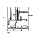
- Bei dem in der Fig. 3 dargestellten Ausführungsbeispiel ist anstelle der Stufenisolierglasscheibe 10 eine herkömmliche Mehrscheibenverglasung 27 vorgesehen, die von dem Halter 28 umgriffen wird. Der Halter 28 weist wie bei dem Ausführungsbeispiel gemäß Fig. 2 eine übereinstimmende Flanschkonstruktion auf, so daß in diesem Zusammenhang auf die vorstehende Beschreibung verwiesen werden kann. Er besitzt darüberhinaus einen in die Beschlagskammer 29 eingreifenden Anschlag 30, der gegen eine Mitteldichtung 31 zur Anlage kommt, wenn der Flügel geschlossen wird.
- Aus den verschiedenen Konstruktionen gemäß Fig. 1 und 3 ist ferner zu entnehmen, daß der Halter 19, 28 im wesentlichen mit dem zur Beschlagskammer 29 weisenden Abschnitt des Flügelrahmenprofilteils 13 bzw. 32 im wesentlichen in einer Ebene liegt und zusammen mit dem Flügelrahmenprofilteil-Abschnitt die Begrenzungswand für die Beschlagskammer 29 bildet.
- Die Auführungsbeispiele der Fig. 4 und 5 zeigen Festverglasungen mit einseitiger und zweiseitiger Anordnung von Stufenisolierglasscheiben, die als sog. Structural Glazing lediglich von Haltern 33, 34 und 35 an entsprechenden Stockrahmenprofilen 36 bzw. 37 gehalten sind, die in entsprechenden Schulterabschnitten 38, 39, 40 Aufnahmenuten der in der Fig. 1 gezeigten Art besitzen.
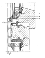
- Bei den in den Fig. 6 und 7 dargestellten Ausführungsbeispielen sind Holzflügel 41 bzw. 42 und Holzsprossen 43 bzw. 44 dargestellt. Der Holzflügel 41 weist eine Aufnahmenut 45 auf, in welcher der innere Schenkel 46 eines Halters 47 eingesetzt ist. Zur Verstärkung der Schulter 48 des Holzflügels 41 ist ein Verstärkungswinkel 49 vorgesehen, der z.B. auf die Schulter aufgenagelt oder aufgeschraubt sein kann.
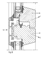
- Bei dem in der Fig. 7 gezeigten Ausführungsbeispiel ist der Holzflügel 42 mit einer Verstärkungsleiste 50 ausgestattet, die einen in den Falzraum 51 der Stufenisolierglasscheibe 52 ragenden Flanschabschnitt 53 aufweist, welcher mit dem senkrechten Schenkel 54 der Verstärkungsleiste 50 eine Aufnahmenut 55 begrenzt, in der der innere Flansch 56 eines Halters 57 aufgenommen wird. Der Schenkel 54 dient gleichzeitig als Anschlag für die Mitteldichtung.
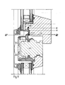
- In der Fig. 8 ist ein sog. Holzstulpflügel 58 gezeigt, welcher einen Holzflügel 59 und einen Holzflügel 60 besitzt. Beim Öffnen des Stulpflügels kann der Holzflügel 60 als Sprosse stehenbleiben, während der Holzflügel 59 aufgeschwenkt wird.
- In der Fig.9 besitzt der Halter 61 zum Zweck der zusätzlichen Befestigung einen nach unten greifenden Steg 62, der auch zugleich als Anschlag für die Mitteldichtung dient.
- Die vorbeschriebene erfindungsgemäße Flügelkonstruktion kann durch die vorteilhafte Ausgestaltung des Halters in norm-und systemgerechte handelsübliche Profilsysteme mit geringen Glasfalzsteghöhen von etwa 20 bis 26 mm.eingesetzt werden. D.h. daß ein vorhandenes System durch die erfindungsgemäße Konstruktion ergänzt werden kann, ohne daß das Systemprogramm in seiner Variabilität eingeschränkt wird. So zeigt beispielsweise die Fig.1 eine Variante mit Flügel- und Festverglasung mit einheitlichem äußeren Erscheinungsbild. Es ist deutlich zu erkennen, daß die Festverglasung gegenüber dem vorhandenen optimierten Systemprogramm keinen verlängerten Schenkel des Blendrahmens 6 erfordert.
Claims (21)
daß der äußere Schenkel (21) des die Mehrscheibenverglasung (10) umfassenden Halters (19) im spitzen Winkel und der innere, raumseitige Schenkel (20) des Halters (19) im stumpfen Winkel zu dem sie verbindenden Steg (22) des Halters angeordnet sind und daß die Aufnahmenut (18) des Flügelprofils (13) eine zur formschlüssigen Aufnahme des raumseitigen Schenkels (20) korrespondierende Ausbildung und Anordnung aufweist.
dadurch gekennzeichnet,
daß der äußere Schenkel (21) des Halters (19) etwa die halbe Länge und Stärke des inneren Schenkels (20) des Halters aufweist.
dadurch gekennzeichnet,
daß der die Schenkel (20, 21) verbindende Steg (22) des Halters (19) einen raumseitig zunehmend stärkeren Querschnitt aufweist.
dadurch gekennzeichnet,
daß die parallelen Schenkelflächen des inneren Schenkels (20) aufgerauht oder mit einer zu den korrespondierenden Nutenflächen passenden Verzahnung (23) versehen sind.
dadurch gekennzeichnet,
daß die Aufnahmenut (18) im Nutengrund einen vergrößerten Querschnitt aufweist.
dadurch gekennzeichnet,
daß der Halter (19) die Mehrscheibenverglasung (10) umlaufend umgreift.
daß der Halter von wenigstens vier an den Ecken der Mehrscheibenverglasung angreifenden Kurzstücken oder Winkelstücken gebildet ist.
dadurch gekennzeichnet,
daß der Halter (19) im Steg angeordnete Öffnungen (24) zur Entwässerung und/oder zum Dampfdruckausgleich aufweist.
daß der Halter aus Kunststoff besteht.
daß der Steg (22) des Halters (19) und der Flügelrahmen (13) im wesentlichen in einer die Beschlagskammer (25) begrenzenden gleichen Ebene liegen.
daß der Halter (28) einen in die Beschlagskammer (29) hineingreifenden Anschlag bzw. Steg (30, 62) aufweist, gegen den im Schließzustand des Flügels (32) eine Mitteldichtung (31) zur Anlage kommt.
daß die Mehrscheibenverglasung (10) von einer Stufenglasscheibe (11, 12) gebildet ist.
daß das Flügelprofil zur Erzielung einer Verkürzung des Halters (19) im Stegbereich (22) bis unter die innere, verkürzte Scheibe (11) des Stufenglases (10) in den Falzraum (15) hinein verlängert ist.
daß das Flügelprofil (13) an dem in den Falzraum hineinragenden Abschnitt wenigstens eine Schulter (14) aufweist, auf welcher die Last der Mehrscheibenverglasung (10) abtragbar ist.
dadurch gekennzeichnet,
daß die äußere, verlängerte Scheibe (12) des Stufenglases (10) im eingebauten Zustand einen stirnseitigen Begrenzungsanschlag für den Einschubweg des Halters (19) bildet.
dadurch gekennzeichnet,
daß das Flügelprofil (41, 42) aus Holz besteht und einen Vollquerschnitt aufweist.
dadurch gekennzeichnet,
daß der in den Falzraum (51) hineinragende Abschnitt des Holzprofils durch einen Metallbeschlag (49, 50) verstärkt ist.
dadurch gekennzeichnet,
daß die Aufnahmenut (55) in dem Metallbeschlag (50) vorgesehen ist.
dadurch gekennzeichnet,
daß die Dichtung (26) des äußeren Blendrahmenprofils (6) den Halter (19) im Schließzustand des Flügels übergreift.
dadurch gekennzeichnet,
daß die den Halter (19) überdeckende Dichtung (26) im Schließzustand des Flügels und die korrespondierende Dichtung (4) der Festverglasung (2) von der Außenseite ein gleiches Erscheinungsbild aufweisen.
dadurch gekennzeichnet,
daß die Flügelkonstruktion unter Verwendung des Halters (19) den Einsatz von herkömmlichen Profilsystemen ohne Veränderung der Basissysteme, i.w. bestehend aus den Blendrahmenprofilen (6, 8) und der Isolierbrücke (9), ermöglicht.
Applications Claiming Priority (2)
| Application Number | Priority Date | Filing Date | Title |
|---|---|---|---|
| DE4022177A DE4022177A1 (de) | 1990-07-12 | 1990-07-12 | Fenster- oder tuerkonstruktion |
| DE4022177 | 1990-07-12 |
Publications (2)
| Publication Number | Publication Date |
|---|---|
| EP0465825A1 true EP0465825A1 (de) | 1992-01-15 |
| EP0465825B1 EP0465825B1 (de) | 1994-10-19 |
Family
ID=6410137
Family Applications (1)
| Application Number | Title | Priority Date | Filing Date |
|---|---|---|---|
| EP91109174A Expired - Lifetime EP0465825B1 (de) | 1990-07-12 | 1991-06-05 | Fenster- oder Türkonstruktion |
Country Status (3)
| Country | Link |
|---|---|
| EP (1) | EP0465825B1 (de) |
| AT (1) | ATE113113T1 (de) |
| DE (2) | DE4022177A1 (de) |
Cited By (9)
| Publication number | Priority date | Publication date | Assignee | Title |
|---|---|---|---|---|
| EP0785335A1 (de) * | 1996-01-17 | 1997-07-23 | Norsk Hydro ASA | Glasrandhalterung |
| FR2753227A1 (fr) * | 1996-09-06 | 1998-03-13 | Ouest Alu | Chassis de fermeture pour batiment, type fenetre ou porte-fenetre vitree, a frappe, a ouvrant(s) cache(s) |
| WO1998017887A1 (de) * | 1996-10-23 | 1998-04-30 | Ruepp Beratungen | Fenster-system |
| EP1136644A3 (de) * | 2000-03-22 | 2002-07-24 | aluplast GmbH | Fenster oder Tür mit Blendrahmen, Flügelrahmen und Verglasung |
| EP1811112A2 (de) | 2006-01-19 | 2007-07-25 | Hermann Gutmann Werke AG | Scheibenverklebung |
| GB2481616A (en) * | 2010-06-30 | 2012-01-04 | William Malcolm Snape | Seal for a door |
| CN104453560A (zh) * | 2014-11-11 | 2015-03-25 | 徐小富 | 组合密封窗 |
| CN107269158A (zh) * | 2017-08-08 | 2017-10-20 | 烟台海林建材有限公司 | 一种下框铝型材及具有排水系统的门窗 |
| CN115807614A (zh) * | 2022-12-20 | 2023-03-17 | 金鹏节能科技有限公司 | 一种通风窗 |
Families Citing this family (4)
| Publication number | Priority date | Publication date | Assignee | Title |
|---|---|---|---|---|
| DE4130149C2 (de) * | 1991-07-27 | 1998-07-23 | Joseph Fischl | Fensterflügel sowie unter Verwendung dieses Flügels ausgebildetes Fenster |
| DE4429666C2 (de) * | 1994-08-20 | 1998-02-26 | Wicona Bausysteme Gmbh | An einem Halterahmen angeordnete Isolierglasscheibe |
| DE29817044U1 (de) | 1998-09-24 | 1998-12-17 | Schüco International KG, 33609 Bielefeld | Blockfenster |
| DE202013105916U1 (de) * | 2013-12-23 | 2015-03-24 | SCHÜCO International KG | Fenster- oder Türflügel mit einer Haltevorrichtung zur Aufnahme eines flügelüberdeckenden Flächenelements |
Citations (9)
| Publication number | Priority date | Publication date | Assignee | Title |
|---|---|---|---|---|
| DE1950670A1 (de) * | 1969-10-08 | 1971-04-15 | Herbert Borkhoff | Drehkipp-,Schwing-,Wende-,Klapp-,Kipp- oder Drehfluegelfenster |
| GB2051197A (en) * | 1979-06-13 | 1981-01-14 | Blacknell Buildings Ltd | Window Mounting Assembly |
| US4314424A (en) * | 1979-12-26 | 1982-02-09 | Gordon Stanley J | Thermal window construction |
| DE3400749A1 (de) * | 1984-01-11 | 1985-07-18 | Frener & Reifer Stahl-Metallbau oHG, 39042 Brixen | Fenster, tuer oder dergleichen |
| DE3500301A1 (de) * | 1985-01-07 | 1986-07-10 | Herbert 6782 Rodalben Borkhoff | Vorsatzrahmenkonstruktion fuer alte und neue fenster und tueren |
| EP0225473A1 (de) * | 1985-12-10 | 1987-06-16 | Eltreva AG | Fenster- oder Türflügel |
| GB2196047A (en) * | 1986-09-17 | 1988-04-20 | Eltreva Ag | Facade construction |
| EP0280832A1 (de) * | 1987-03-05 | 1988-09-07 | Metallbau Koller AG | Plattenkonstruktion für eine Fassade oder ein Dach |
| FR2633328A1 (fr) * | 1988-06-28 | 1989-12-29 | Alcan France Aluminium | Piece de securite, notamment pour vitrage colle |
-
1990
- 1990-07-12 DE DE4022177A patent/DE4022177A1/de not_active Withdrawn
-
1991
- 1991-06-05 DE DE59103268T patent/DE59103268D1/de not_active Expired - Fee Related
- 1991-06-05 EP EP91109174A patent/EP0465825B1/de not_active Expired - Lifetime
- 1991-06-05 AT AT91109174T patent/ATE113113T1/de not_active IP Right Cessation
Patent Citations (9)
| Publication number | Priority date | Publication date | Assignee | Title |
|---|---|---|---|---|
| DE1950670A1 (de) * | 1969-10-08 | 1971-04-15 | Herbert Borkhoff | Drehkipp-,Schwing-,Wende-,Klapp-,Kipp- oder Drehfluegelfenster |
| GB2051197A (en) * | 1979-06-13 | 1981-01-14 | Blacknell Buildings Ltd | Window Mounting Assembly |
| US4314424A (en) * | 1979-12-26 | 1982-02-09 | Gordon Stanley J | Thermal window construction |
| DE3400749A1 (de) * | 1984-01-11 | 1985-07-18 | Frener & Reifer Stahl-Metallbau oHG, 39042 Brixen | Fenster, tuer oder dergleichen |
| DE3500301A1 (de) * | 1985-01-07 | 1986-07-10 | Herbert 6782 Rodalben Borkhoff | Vorsatzrahmenkonstruktion fuer alte und neue fenster und tueren |
| EP0225473A1 (de) * | 1985-12-10 | 1987-06-16 | Eltreva AG | Fenster- oder Türflügel |
| GB2196047A (en) * | 1986-09-17 | 1988-04-20 | Eltreva Ag | Facade construction |
| EP0280832A1 (de) * | 1987-03-05 | 1988-09-07 | Metallbau Koller AG | Plattenkonstruktion für eine Fassade oder ein Dach |
| FR2633328A1 (fr) * | 1988-06-28 | 1989-12-29 | Alcan France Aluminium | Piece de securite, notamment pour vitrage colle |
Cited By (10)
| Publication number | Priority date | Publication date | Assignee | Title |
|---|---|---|---|---|
| EP0785335A1 (de) * | 1996-01-17 | 1997-07-23 | Norsk Hydro ASA | Glasrandhalterung |
| FR2753227A1 (fr) * | 1996-09-06 | 1998-03-13 | Ouest Alu | Chassis de fermeture pour batiment, type fenetre ou porte-fenetre vitree, a frappe, a ouvrant(s) cache(s) |
| WO1998017887A1 (de) * | 1996-10-23 | 1998-04-30 | Ruepp Beratungen | Fenster-system |
| EP1136644A3 (de) * | 2000-03-22 | 2002-07-24 | aluplast GmbH | Fenster oder Tür mit Blendrahmen, Flügelrahmen und Verglasung |
| EP1811112A2 (de) | 2006-01-19 | 2007-07-25 | Hermann Gutmann Werke AG | Scheibenverklebung |
| EP1811112A3 (de) * | 2006-01-19 | 2012-03-14 | Gutmann Ag | Scheibenverklebung |
| GB2481616A (en) * | 2010-06-30 | 2012-01-04 | William Malcolm Snape | Seal for a door |
| CN104453560A (zh) * | 2014-11-11 | 2015-03-25 | 徐小富 | 组合密封窗 |
| CN107269158A (zh) * | 2017-08-08 | 2017-10-20 | 烟台海林建材有限公司 | 一种下框铝型材及具有排水系统的门窗 |
| CN115807614A (zh) * | 2022-12-20 | 2023-03-17 | 金鹏节能科技有限公司 | 一种通风窗 |
Also Published As
| Publication number | Publication date |
|---|---|
| EP0465825B1 (de) | 1994-10-19 |
| DE4022177A1 (de) | 1992-01-16 |
| DE59103268D1 (de) | 1994-11-24 |
| ATE113113T1 (de) | 1994-11-15 |
Similar Documents
| Publication | Publication Date | Title |
|---|---|---|
| EP0465825B1 (de) | Fenster- oder Türkonstruktion | |
| DE19601505C1 (de) | Glasrandhalterung | |
| EP1026357B1 (de) | Rahmenprofil für Holz-Metall-Fenster oder -Türen | |
| EP3783187B1 (de) | System mit einem fenster, einer verschattungsanlage und einem entwässerungselement | |
| CH677252A5 (de) | ||
| DE19505222C2 (de) | Flügelanordnung, im wesentlichen bestehend aus einem Stockrahmen und zwei an diesem Stockrahmen schwenkbar vorgesehenen Flügelrahmen | |
| DE4338181C1 (de) | Kunststoff-Hohlprofil | |
| DE2203356A1 (de) | Fenster oder tuer | |
| DE10140708A1 (de) | Sicherheitsglasfalzeinlage/Sicherheitsverglasungsklotz | |
| EP1070820A2 (de) | Fenster | |
| EP3677746B1 (de) | Profileinheit zur rollladenführung und befestigung wenigstens eines absturzsicherungselements an einem blendrahmen oder pfosten eines fensters | |
| EP1510644A2 (de) | Fenster- oder Türkonstruktion | |
| EP0953710A2 (de) | Fensterbank zur Befestigung an der Aussenseite eines Fensterrahmens | |
| DE29704349U1 (de) | Hohlprofil, insbesondere aus Kunststoff, zur Bildung eines Abdeckrahmens zur Verkleidung von Holzrahmen | |
| DE2844680A1 (de) | Fenstersprosse eines sprossenfensters | |
| DE29504638U1 (de) | Fassadenelement in Form eines Fensters oder einer Tür | |
| CH662154A5 (en) | Window leaf with wooden frame | |
| DE102020108505A1 (de) | Befestigungssystem für Absturzsicherung | |
| DE10001406B4 (de) | Türrahmen mit einer Trittschutzleiste | |
| DE3528388A1 (de) | Elastische profildichtung fuer isolierverglasungen | |
| DE19634611C1 (de) | Blendrahmen eines Kunststoff-Fensters oder einer Kunststoff-Türe | |
| CH532185A (de) | Metalleinfassung für Fenster und Türen | |
| DE102022120797A1 (de) | Isoliersteg zum Verbinden zweier Profilelemente zur Herstellung eines wärmegedämmten Profils und ein solches Profil | |
| DE29801925U1 (de) | Kämpferverbinder | |
| EP0886028A2 (de) | Halteprofil |
Legal Events
| Date | Code | Title | Description |
|---|---|---|---|
| PUAI | Public reference made under article 153(3) epc to a published international application that has entered the european phase |
Free format text: ORIGINAL CODE: 0009012 |
|
| AK | Designated contracting states |
Kind code of ref document: A1 Designated state(s): AT CH DE FR GB LI |
|
| 17P | Request for examination filed |
Effective date: 19920302 |
|
| 17Q | First examination report despatched |
Effective date: 19921203 |
|
| GRAA | (expected) grant |
Free format text: ORIGINAL CODE: 0009210 |
|
| AK | Designated contracting states |
Kind code of ref document: B1 Designated state(s): AT CH DE FR GB LI |
|
| REF | Corresponds to: |
Ref document number: 113113 Country of ref document: AT Date of ref document: 19941115 Kind code of ref document: T |
|
| REF | Corresponds to: |
Ref document number: 59103268 Country of ref document: DE Date of ref document: 19941124 |
|
| GBT | Gb: translation of ep patent filed (gb section 77(6)(a)/1977) |
Effective date: 19941103 |
|
| ET | Fr: translation filed | ||
| PGFP | Annual fee paid to national office [announced via postgrant information from national office to epo] |
Ref country code: GB Payment date: 19950530 Year of fee payment: 5 |
|
| PGFP | Annual fee paid to national office [announced via postgrant information from national office to epo] |
Ref country code: FR Payment date: 19950619 Year of fee payment: 5 |
|
| PGFP | Annual fee paid to national office [announced via postgrant information from national office to epo] |
Ref country code: CH Payment date: 19950621 Year of fee payment: 5 |
|
| PGFP | Annual fee paid to national office [announced via postgrant information from national office to epo] |
Ref country code: AT Payment date: 19950623 Year of fee payment: 5 |
|
| PLBE | No opposition filed within time limit |
Free format text: ORIGINAL CODE: 0009261 |
|
| STAA | Information on the status of an ep patent application or granted ep patent |
Free format text: STATUS: NO OPPOSITION FILED WITHIN TIME LIMIT |
|
| PGFP | Annual fee paid to national office [announced via postgrant information from national office to epo] |
Ref country code: DE Payment date: 19950824 Year of fee payment: 5 |
|
| 26N | No opposition filed | ||
| PG25 | Lapsed in a contracting state [announced via postgrant information from national office to epo] |
Ref country code: GB Effective date: 19960605 Ref country code: AT Effective date: 19960605 |
|
| PG25 | Lapsed in a contracting state [announced via postgrant information from national office to epo] |
Ref country code: LI Effective date: 19960630 Ref country code: CH Effective date: 19960630 |
|
| GBPC | Gb: european patent ceased through non-payment of renewal fee |
Effective date: 19960605 |
|
| REG | Reference to a national code |
Ref country code: CH Ref legal event code: PL |
|
| PG25 | Lapsed in a contracting state [announced via postgrant information from national office to epo] |
Ref country code: FR Effective date: 19970228 |
|
| PG25 | Lapsed in a contracting state [announced via postgrant information from national office to epo] |
Ref country code: DE Effective date: 19970301 |
|
| REG | Reference to a national code |
Ref country code: FR Ref legal event code: ST |