EP0458121A1 - Vorrichtung und Verfahren zur Fehlererfassung in einem Geschwindigkeitsmessystem - Google Patents
Vorrichtung und Verfahren zur Fehlererfassung in einem Geschwindigkeitsmessystem Download PDFInfo
- Publication number
- EP0458121A1 EP0458121A1 EP91107364A EP91107364A EP0458121A1 EP 0458121 A1 EP0458121 A1 EP 0458121A1 EP 91107364 A EP91107364 A EP 91107364A EP 91107364 A EP91107364 A EP 91107364A EP 0458121 A1 EP0458121 A1 EP 0458121A1
- Authority
- EP
- European Patent Office
- Prior art keywords
- value
- rate
- change
- time
- rotational speed
- Prior art date
- Legal status (The legal status is an assumption and is not a legal conclusion. Google has not performed a legal analysis and makes no representation as to the accuracy of the status listed.)
- Granted
Links
Images
Classifications
-
- G—PHYSICS
- G01—MEASURING; TESTING
- G01P—MEASURING LINEAR OR ANGULAR SPEED, ACCELERATION, DECELERATION, OR SHOCK; INDICATING PRESENCE, ABSENCE, OR DIRECTION, OF MOVEMENT
- G01P3/00—Measuring linear or angular speed; Measuring differences of linear or angular speeds
-
- G—PHYSICS
- G01—MEASURING; TESTING
- G01P—MEASURING LINEAR OR ANGULAR SPEED, ACCELERATION, DECELERATION, OR SHOCK; INDICATING PRESENCE, ABSENCE, OR DIRECTION, OF MOVEMENT
- G01P3/00—Measuring linear or angular speed; Measuring differences of linear or angular speeds
- G01P3/42—Devices characterised by the use of electric or magnetic means
- G01P3/44—Devices characterised by the use of electric or magnetic means for measuring angular speed
- G01P3/48—Devices characterised by the use of electric or magnetic means for measuring angular speed by measuring frequency of generated current or voltage
- G01P3/481—Devices characterised by the use of electric or magnetic means for measuring angular speed by measuring frequency of generated current or voltage of pulse signals
- G01P3/489—Digital circuits therefor
Definitions
- the present invention relates to a system/method for detecting faults in the output signals from rotational speed sensors.
- the present invention relates to a system/method for detecting faults, particularly "tooth drop-out" type faults, in rotational speed sensors of the type comprising a relatively rotatable toothed rotor which rotates past a rotationally fixed sensor or stator member.
- Rotational speed sensors which utilize a relatively rotatable toothed rotor which rotates past a relatively fixed sensor or the like are well known in the prior art. Examples of such speed sensor assemblies may be seen by reference to U.S. Patent Nos. RE 30,522; 3,961,215; 4,862,025; 4,862,028 and 4,893,075, the disclosures of which are hereby incorporated herein by reference. Such rotational speed sensors are often used in connection with automated vehicular components/systems such as automatic fuel controls, automated transmission systems and/or vehicular anti-lock brake systems (ABS).
- ABS vehicular anti-lock brake systems
- rotational speed sensor assemblies are electromagnetic in nature and rely on the alignment of rotor teeth or spaces between rotor teeth rotating past a sensor to complete or break, respectively, a magnetic flux path to produce a digital or analog signal indicative of the rotational speed of the rotor.
- the drawbacks of the prior art have been minimized or overcome by the provision of a fault sensing technique for detecting if a "missed” or “dropped tooth” speed sensor reading has occurred and, if sensed, for going into a "fail safe” or a “fail soft” logic routine.
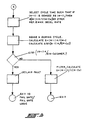
- a predetermined reference value selected to represent the greatest expected wheel deceleration, such as -25G to -30G for example. If the current change in S, or dS/dt, is greater than a predetermined reference value (REF) selected to represent the greatest expected wheel deceleration, such as -25G to -30G for example, then a single or multiple "tooth drop-out" error is sensed and the system will either shut off (“fail safe”) or go into a fault tolerant (“fail soft”) mode of operation.
- REF predetermined reference value
- the time duration of the loop is selected so that a false reading of (N-1) by a single unit will either not effect the calculated value of S or will be detectable (i.e. will cause dS/dt to exceed the reference value REF).
- the fault check logic is preformed prior to any filtering of the sensor input signal.
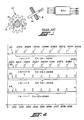
- Figure 1 is a schematic illustration of a toothed rotor type speed sensor assembly.
- Figure 2 is a graphical illustration of the output signals from a typical prior art rotational speed sensor.
- FIG. 3 is a schematic illustration, in flow chart format, of the control system/method of the present invention.
- control system/control method of the present invention is intended for use in connection with rotational speed sensor assemblies of the type typically utilized to provide input signals to the controllers (CPUs) of vehicular automated drivetrain and/or braking systems.
- controllers CPUs
- Vehicular ABS and automated drivetrain systems are well known in the prior art and examples thereof may be seen by reference to U.S. Patent Nos. 3,920,284; 3,929 382; 4,168,866; 4,478,840; 4,818,035; 4,863,221; 4,361,060; 4,527,447; 4,643,048 and 4,860,861, the disclosures of all of which are hereby incorporated herein by reference.
- Speed sensor assemblies for providing input signals to control units are well known in the prior art as may be seen by reference to above-mentioned U.S. Patent Nos. RE 30522; 3,961,215; 4,862,025; 4,862,028 and 4,893,075.
- speed sensor assemblies 10 include a toothed ferromagnetic rotor 12 which is keyed to a monitored shaft 14 for rotation therewith and a stator or sensor member 16 rotationally fixed relative to a vehicle component 18 for providing signals indicative of the rotational speed of the rotor.
- the present invention is particularly well suited for use with toothed rotor type electromagnetic speed sensor assemblies of the type schematically illustrated in Figure 1, the present invention is equally applicable to any type of speed sensor assembly providing an output in the form of pulses the frequency of which is indicative of the rotational speed of the monitored members.
- FIG. 2 is a graphical illustration of the output of a typical pulse type speed sensor assembly and of the use of said pulses to calculate a rotational speed of the monitored shaft 14.
- S (N-1)K/(C N -C O )
- N number of teeth counts per fixed duration time loop (0.010 second for example)
- K a constant
- C N time of last N count
- C O time of first N count.
- K depends upon the number of teeth on the rotor (60 tooth and 100 tooth rotors are typical in ABS systems), gear ratios, tire sizes and the like.
- K 860 cycles per second (HZ) at 100 mph vehicle speed.
- line traces 20 and 22 illustrate proper operation of the sensor assembly 10.
- a tooth pulse should be generated by the sensor assembly every 0.0012 second (1/860).
- the first pulse will be received exactly 0.0012 seconds after the start of the first cycle and thus, assuming substantially constant vehicle speed, eight (8) tooth pulses will be counted during the testing cycle.
- (N-1) will equal seven (7)
- C N -C O will equal 0.0012 - 0.0096
- 0.0084 or one pulse every 0.0012 seconds which corresponds to the calibration of 860 pulses per second equaling 100 mph.
- any wheel acceleration exceeding a reference value of approximately -25 or -30g may be considered indicative of an error.
- (N-1) will equal seven (7)
- C N -C O will equal .0084 resulting in a frequency of tooth pulse of one every .0012 second which, while not allowing sensing of a tooth drop-out problem, will result in an accurate indication of vehicular speed.
- the tooth drop-out will eventually occur other than at the very beginning or the very end of the testing cycle and will allow fault detection thereof.
- N 4
- C N - C O .0072 (.0024 - .0096) which is a pulse every 0.0024 second. If a tooth or pulse is "dropped", N-1 will equal 2, which indicates a pulse every 0.0036 second or a vehicle deceleration of about 75G which will, of course, exceed the reference REF.
- K will equal 1400 KZ at 100 MPH vehicle speed (700 KZ at 50 MPH vehicle speed) and a dropped tooth pulse will result in an apparent vehicle acceleration of about -35g at true 100 MPH and about -38g at true 50 MPH vehicle speeds, both of which will exceed the selected reference.
- the system Upon sensing of a tooth drop-out fault, the system will, preferably, indicate the existence of a fault to the vehicle operator and will take appropriate action in the form of either fail safe or fail soft logic.
- a fail safe logic situation the automated system utilizing the sensor assembly 10 will simply discontinue operation which may render the vehicle inoperative.
- a fail soft situation usually associated with non-vehicle safety related equipment, a fault tolerance logic will be utilized.
- the logic may utilize transmission input shaft speed as a substitute therefor. Fault tolerance logic of this nature may be seen by reference to U.S. Patent No. 4,849,899, the disclosure of which is hereby incorporated by reference.
- a cycle time is selected such that if the true value of N-1 is misread as N-2 or less, then the change or first time derivative of calculated vehicle speed will exceed the predetermined reference value.
- the predetermined reference value is about -20 to -30g which exceeds the maximum vehicle deceleration rate expected in vehicular applications.
Applications Claiming Priority (2)
| Application Number | Priority Date | Filing Date | Title |
|---|---|---|---|
| US528521 | 1990-05-25 | ||
| US07/528,521 US5095269A (en) | 1990-05-25 | 1990-05-25 | Speed sensor fault detection system and method |
Publications (2)
| Publication Number | Publication Date |
|---|---|
| EP0458121A1 true EP0458121A1 (de) | 1991-11-27 |
| EP0458121B1 EP0458121B1 (de) | 1995-07-19 |
Family
ID=24106017
Family Applications (1)
| Application Number | Title | Priority Date | Filing Date |
|---|---|---|---|
| EP91107364A Expired - Lifetime EP0458121B1 (de) | 1990-05-25 | 1991-05-07 | Vorrichtung und Verfahren zur Fehlererfassung in einem Geschwindigkeitsmessystem |
Country Status (8)
| Country | Link |
|---|---|
| US (1) | US5095269A (de) |
| EP (1) | EP0458121B1 (de) |
| JP (1) | JPH0674961A (de) |
| KR (1) | KR960012785B1 (de) |
| AU (1) | AU636274B2 (de) |
| BR (1) | BR9102149A (de) |
| CA (1) | CA2043238C (de) |
| DE (1) | DE69111300T2 (de) |
Cited By (4)
| Publication number | Priority date | Publication date | Assignee | Title |
|---|---|---|---|---|
| DE19602359A1 (de) * | 1996-01-24 | 1997-07-31 | Teves Gmbh Alfred | Verfahren und Schaltungsanordnung zur Überwachung eines Drehzahlsensors |
| DE19749791A1 (de) * | 1997-11-11 | 1999-05-12 | Wabco Gmbh | Auswerteverfahren für ein Ausgangssignal einer eine zyklische Bewegung abtastenden Sensoreinrichtung |
| WO2007033914A1 (de) * | 2005-09-22 | 2007-03-29 | Siemens Vdo Automotive Ag | Verfahren zur drehzahlüberwachung einer turbowelle |
| US8886471B2 (en) | 2008-06-26 | 2014-11-11 | Infineon Technologies Ag | Rotation sensing method and system |
Families Citing this family (10)
| Publication number | Priority date | Publication date | Assignee | Title |
|---|---|---|---|---|
| US5343396A (en) * | 1992-04-29 | 1994-08-30 | Youngblood Richard J | Sensor malfunction detection |
| US5264789A (en) * | 1992-07-27 | 1993-11-23 | Eaton Corporation | Method of determining the direction of rotation of a member using a rotor having a predetermined pattern of exciter surfaces |
| DE19622462B4 (de) * | 1996-06-05 | 2004-12-09 | Robert Bosch Gmbh | Verfahren und Vorrichtung zur Fehlererkennung |
| DE10162599B4 (de) * | 2001-12-20 | 2020-02-20 | Robert Bosch Gmbh | Verfahren und Vorrichtung zur Überwachung von Drehzahlfühlern auf fehlende Zähne |
| JP2008261883A (ja) * | 2003-01-10 | 2008-10-30 | Toyota Motor Corp | 車両および診断装置 |
| TW200821460A (en) * | 2006-07-11 | 2008-05-16 | Yamaha Motor Co Ltd | Internal combustion engine controlling apparatus and automotive vehicle incorporating the same |
| KR101134908B1 (ko) * | 2006-09-08 | 2012-04-17 | 주식회사 만도 | 차륜 속도 센서의 고장 검출 방법 |
| FR2987085B1 (fr) * | 2012-02-20 | 2014-03-21 | Snecma | Procede de securisation du fonctionnement d'une turbomachine |
| DE102015212944A1 (de) * | 2015-07-10 | 2017-01-12 | Continental Automotive Gmbh | Verfahren und Vorrichtung zum Ermitteln von Drehwinkelgeschwindigkeiten und/oder Drehwinkelpositionen von Fahrzeugrädern eines Kraftfahrzeuges, sowie zum Lokalisieren der Verbaupositionen von an den Fahrzeugrädern angeordneten Radeinheiten |
| GB201714978D0 (en) * | 2017-09-18 | 2017-11-01 | Trw Ltd | Detecting misalignment |
Citations (3)
| Publication number | Priority date | Publication date | Assignee | Title |
|---|---|---|---|---|
| US3908116A (en) * | 1974-08-16 | 1975-09-23 | Rockwell International Corp | Digital data filter |
| DE3426663A1 (de) * | 1983-07-20 | 1985-01-31 | Nippondenso Co., Ltd., Kariya, Aichi | Gegenueber stoerungen unempfindliche vorrichtung zum erfassen von radgeschwindigkeiten und radbeschleunigungen sowie verfahren hierzu |
| US4849899A (en) * | 1986-04-07 | 1989-07-18 | Eaton Corporation | Method for controlling AMT system including speed sensor signal fault detection and tolerance |
Family Cites Families (14)
| Publication number | Priority date | Publication date | Assignee | Title |
|---|---|---|---|---|
| US3961215A (en) * | 1973-12-26 | 1976-06-01 | Eaton Corporation | Rotor for wheel speed sensor assembly |
| US3929382A (en) * | 1974-05-10 | 1975-12-30 | Eaton Corp | Skid control system |
| US3920284A (en) * | 1974-05-10 | 1975-11-18 | Eaton Corp | Monitoring circuitry for a skid control system |
| DE2644646C2 (de) * | 1976-10-02 | 1983-04-07 | Robert Bosch Gmbh, 7000 Stuttgart | Vorrichtung zur Erkennung eines oder mehrerer fehlender Impulse in einer sonst regelmäßigen Impulsfolge |
| US4168866A (en) * | 1977-09-09 | 1979-09-25 | Eaton Corporation | Anti-wheel lock system |
| JPS59210374A (ja) * | 1983-05-16 | 1984-11-29 | Nissan Motor Co Ltd | 車輪速演算装置 |
| GB8605152D0 (en) * | 1986-03-03 | 1986-04-09 | Hughes Ltd Stewart | Digital tachometer |
| US4768840A (en) * | 1987-04-27 | 1988-09-06 | Eaton Corporation | Brake control system and method |
| US4818035A (en) * | 1987-04-27 | 1989-04-04 | Eaton Corporation | Tractor-trailer brake control system |
| US4835467A (en) * | 1988-01-25 | 1989-05-30 | General Motors Corporation | Wheel speed sensor |
| US4863221A (en) * | 1988-08-18 | 1989-09-05 | Eaton Corporation | Tandem drive axle anti-lock brake system |
| US4862028A (en) * | 1988-08-25 | 1989-08-29 | Eaton Corporation | Exciter rotor assembly |
| US4862025A (en) * | 1988-08-25 | 1989-08-29 | Eaton Corporation | Dual speed sensor pickup assembly |
| US4893075A (en) * | 1988-08-29 | 1990-01-09 | Eaton Corporation | Dual speed sensor pickup assembly with anti-cross talk coils |
-
1990
- 1990-05-25 US US07/528,521 patent/US5095269A/en not_active Expired - Fee Related
-
1991
- 1991-05-07 DE DE69111300T patent/DE69111300T2/de not_active Expired - Fee Related
- 1991-05-07 EP EP91107364A patent/EP0458121B1/de not_active Expired - Lifetime
- 1991-05-14 KR KR1019910007787A patent/KR960012785B1/ko not_active IP Right Cessation
- 1991-05-16 AU AU77090/91A patent/AU636274B2/en not_active Ceased
- 1991-05-21 BR BR919102149A patent/BR9102149A/pt not_active IP Right Cessation
- 1991-05-24 JP JP3149907A patent/JPH0674961A/ja active Pending
- 1991-05-24 CA CA002043238A patent/CA2043238C/en not_active Expired - Fee Related
Patent Citations (3)
| Publication number | Priority date | Publication date | Assignee | Title |
|---|---|---|---|---|
| US3908116A (en) * | 1974-08-16 | 1975-09-23 | Rockwell International Corp | Digital data filter |
| DE3426663A1 (de) * | 1983-07-20 | 1985-01-31 | Nippondenso Co., Ltd., Kariya, Aichi | Gegenueber stoerungen unempfindliche vorrichtung zum erfassen von radgeschwindigkeiten und radbeschleunigungen sowie verfahren hierzu |
| US4849899A (en) * | 1986-04-07 | 1989-07-18 | Eaton Corporation | Method for controlling AMT system including speed sensor signal fault detection and tolerance |
Non-Patent Citations (1)
| Title |
|---|
| PATENT ABSTRACTS OF JAPAN, vol. 10, no. 215 (P-481)[2271], 26th July 1986; & JP-A-61 54 456 (TOYODA AUTOM LOOM WORKS LTD) 18-03-1986 * |
Cited By (7)
| Publication number | Priority date | Publication date | Assignee | Title |
|---|---|---|---|---|
| DE19602359A1 (de) * | 1996-01-24 | 1997-07-31 | Teves Gmbh Alfred | Verfahren und Schaltungsanordnung zur Überwachung eines Drehzahlsensors |
| DE19749791A1 (de) * | 1997-11-11 | 1999-05-12 | Wabco Gmbh | Auswerteverfahren für ein Ausgangssignal einer eine zyklische Bewegung abtastenden Sensoreinrichtung |
| WO2007033914A1 (de) * | 2005-09-22 | 2007-03-29 | Siemens Vdo Automotive Ag | Verfahren zur drehzahlüberwachung einer turbowelle |
| DE102005045457A1 (de) * | 2005-09-22 | 2007-04-05 | Siemens Ag | Verfahren zur Drehzahlüberwachung einer Turbowelle |
| DE102005045457B4 (de) * | 2005-09-22 | 2014-10-02 | Continental Automotive Gmbh | Verfahren zur Drehzahlüberwachung einer Turbowelle |
| US8886471B2 (en) | 2008-06-26 | 2014-11-11 | Infineon Technologies Ag | Rotation sensing method and system |
| US9869568B2 (en) | 2008-06-26 | 2018-01-16 | Infineon Technologies Ag | Sensing method and system for correcting an input waveform from a coded wheel |
Also Published As
| Publication number | Publication date |
|---|---|
| AU636274B2 (en) | 1993-04-22 |
| JPH0674961A (ja) | 1994-03-18 |
| CA2043238A1 (en) | 1991-11-26 |
| CA2043238C (en) | 1997-11-18 |
| DE69111300D1 (de) | 1995-08-24 |
| EP0458121B1 (de) | 1995-07-19 |
| BR9102149A (pt) | 1991-12-24 |
| KR960012785B1 (ko) | 1996-09-24 |
| DE69111300T2 (de) | 1996-04-04 |
| US5095269A (en) | 1992-03-10 |
| AU7709091A (en) | 1991-11-28 |
| KR910020444A (ko) | 1991-12-20 |
Similar Documents
| Publication | Publication Date | Title |
|---|---|---|
| US5095269A (en) | Speed sensor fault detection system and method | |
| EP1155330B1 (de) | Verfahren zur erkennung von signalfehlern | |
| KR100403228B1 (ko) | 회전속도센서에서의에러인식방법 | |
| US4347569A (en) | Wheel slip system | |
| US4495578A (en) | Microprocessor based over/under speed governor | |
| US6204658B1 (en) | Method for evaluating an output signal of a rotational sensing device | |
| US6502025B1 (en) | Relative steering angle sensor diagnostic for momentary signal dropout | |
| JP3591191B2 (ja) | 検出手段異常判別装置 | |
| CN1280632C (zh) | 磁旋转检测器、相关车辆控制装置和判断转子异常的方法 | |
| EP0607690A1 (de) | Verfahren und Vorrichtung zur Erkennen von Reifenfehlern | |
| EP0581470A1 (de) | Verfahren zur Bestimmung der Drehrichtung eines Teiles | |
| EP0567862B1 (de) | Erfassung von Sensor-Defekt | |
| JPH11508212A (ja) | 電磁妨害雑音を検知する装置 | |
| US20140009141A1 (en) | Method for Operating a Speed Sensing Device | |
| US6525529B2 (en) | Method and apparatus for detecting broken teeth in a pulse signal of a wheel speed sensor for an ABS vehicle stabilization system | |
| CN112519835B (zh) | 列车速度确定方法、装置、电子设备和可读存储介质 | |
| HU214278B (hu) | Eljárás és biztonsági kapcsolási elrendezés blokkolásgátló elektronikával felszerelt járműfékrendszerek helyes működésének ellenőrzésére | |
| CN111380708A (zh) | 列车轴抱死故障诊断方法及列车轴抱死故障诊断系统 | |
| JPS6358167A (ja) | 回転センサの故障検出装置 | |
| CA2059452C (en) | Speed sensor failure detection method and apparatus for an overspeed protection system | |
| US6485114B2 (en) | Sensor error detection in a dual sensor system | |
| US20190066405A1 (en) | Method and system for detecting a road impact event and for diagnosing abnormalities in chassis components | |
| US5727855A (en) | Anti-locking control system | |
| CN110343844B (zh) | 一种连续退火机组活套套量控制方法及装置 | |
| KR100413254B1 (ko) | 차륜속도센서의이상상태판단방법 |
Legal Events
| Date | Code | Title | Description |
|---|---|---|---|
| PUAI | Public reference made under article 153(3) epc to a published international application that has entered the european phase |
Free format text: ORIGINAL CODE: 0009012 |
|
| AK | Designated contracting states |
Kind code of ref document: A1 Designated state(s): DE FR GB IT SE |
|
| 17P | Request for examination filed |
Effective date: 19920123 |
|
| 17Q | First examination report despatched |
Effective date: 19930603 |
|
| GRAA | (expected) grant |
Free format text: ORIGINAL CODE: 0009210 |
|
| AK | Designated contracting states |
Kind code of ref document: B1 Designated state(s): DE FR GB IT SE |
|
| REF | Corresponds to: |
Ref document number: 69111300 Country of ref document: DE Date of ref document: 19950824 |
|
| ET | Fr: translation filed | ||
| ITF | It: translation for a ep patent filed |
Owner name: ING. C. GREGORJ S.P.A. |
|
| PLBE | No opposition filed within time limit |
Free format text: ORIGINAL CODE: 0009261 |
|
| STAA | Information on the status of an ep patent application or granted ep patent |
Free format text: STATUS: NO OPPOSITION FILED WITHIN TIME LIMIT |
|
| 26N | No opposition filed | ||
| PGFP | Annual fee paid to national office [announced via postgrant information from national office to epo] |
Ref country code: FR Payment date: 19980408 Year of fee payment: 8 |
|
| PGFP | Annual fee paid to national office [announced via postgrant information from national office to epo] |
Ref country code: GB Payment date: 19980417 Year of fee payment: 8 |
|
| PGFP | Annual fee paid to national office [announced via postgrant information from national office to epo] |
Ref country code: SE Payment date: 19980506 Year of fee payment: 8 |
|
| PGFP | Annual fee paid to national office [announced via postgrant information from national office to epo] |
Ref country code: DE Payment date: 19980529 Year of fee payment: 8 |
|
| PG25 | Lapsed in a contracting state [announced via postgrant information from national office to epo] |
Ref country code: GB Free format text: LAPSE BECAUSE OF NON-PAYMENT OF DUE FEES Effective date: 19990507 |
|
| PG25 | Lapsed in a contracting state [announced via postgrant information from national office to epo] |
Ref country code: SE Free format text: LAPSE BECAUSE OF NON-PAYMENT OF DUE FEES Effective date: 19990508 |
|
| GBPC | Gb: european patent ceased through non-payment of renewal fee |
Effective date: 19990507 |
|
| EUG | Se: european patent has lapsed |
Ref document number: 91107364.1 |
|
| PG25 | Lapsed in a contracting state [announced via postgrant information from national office to epo] |
Ref country code: FR Free format text: LAPSE BECAUSE OF NON-PAYMENT OF DUE FEES Effective date: 20000131 |
|
| PG25 | Lapsed in a contracting state [announced via postgrant information from national office to epo] |
Ref country code: DE Free format text: LAPSE BECAUSE OF NON-PAYMENT OF DUE FEES Effective date: 20000301 |
|
| REG | Reference to a national code |
Ref country code: FR Ref legal event code: ST |
|
| PG25 | Lapsed in a contracting state [announced via postgrant information from national office to epo] |
Ref country code: IT Free format text: LAPSE BECAUSE OF NON-PAYMENT OF DUE FEES;WARNING: LAPSES OF ITALIAN PATENTS WITH EFFECTIVE DATE BEFORE 2007 MAY HAVE OCCURRED AT ANY TIME BEFORE 2007. THE CORRECT EFFECTIVE DATE MAY BE DIFFERENT FROM THE ONE RECORDED. Effective date: 20050507 |