EP0458121A1 - Speed sensor fault detection system and method - Google Patents
Speed sensor fault detection system and method Download PDFInfo
- Publication number
- EP0458121A1 EP0458121A1 EP91107364A EP91107364A EP0458121A1 EP 0458121 A1 EP0458121 A1 EP 0458121A1 EP 91107364 A EP91107364 A EP 91107364A EP 91107364 A EP91107364 A EP 91107364A EP 0458121 A1 EP0458121 A1 EP 0458121A1
- Authority
- EP
- European Patent Office
- Prior art keywords
- value
- rate
- change
- time
- rotational speed
- Prior art date
- Legal status (The legal status is an assumption and is not a legal conclusion. Google has not performed a legal analysis and makes no representation as to the accuracy of the status listed.)
- Granted
Links
Images
Classifications
-
- G—PHYSICS
- G01—MEASURING; TESTING
- G01P—MEASURING LINEAR OR ANGULAR SPEED, ACCELERATION, DECELERATION, OR SHOCK; INDICATING PRESENCE, ABSENCE, OR DIRECTION, OF MOVEMENT
- G01P3/00—Measuring linear or angular speed; Measuring differences of linear or angular speeds
-
- G—PHYSICS
- G01—MEASURING; TESTING
- G01P—MEASURING LINEAR OR ANGULAR SPEED, ACCELERATION, DECELERATION, OR SHOCK; INDICATING PRESENCE, ABSENCE, OR DIRECTION, OF MOVEMENT
- G01P3/00—Measuring linear or angular speed; Measuring differences of linear or angular speeds
- G01P3/42—Devices characterised by the use of electric or magnetic means
- G01P3/44—Devices characterised by the use of electric or magnetic means for measuring angular speed
- G01P3/48—Devices characterised by the use of electric or magnetic means for measuring angular speed by measuring frequency of generated current or voltage
- G01P3/481—Devices characterised by the use of electric or magnetic means for measuring angular speed by measuring frequency of generated current or voltage of pulse signals
- G01P3/489—Digital circuits therefor
Definitions
- the present invention relates to a system/method for detecting faults in the output signals from rotational speed sensors.
- the present invention relates to a system/method for detecting faults, particularly "tooth drop-out" type faults, in rotational speed sensors of the type comprising a relatively rotatable toothed rotor which rotates past a rotationally fixed sensor or stator member.
- Rotational speed sensors which utilize a relatively rotatable toothed rotor which rotates past a relatively fixed sensor or the like are well known in the prior art. Examples of such speed sensor assemblies may be seen by reference to U.S. Patent Nos. RE 30,522; 3,961,215; 4,862,025; 4,862,028 and 4,893,075, the disclosures of which are hereby incorporated herein by reference. Such rotational speed sensors are often used in connection with automated vehicular components/systems such as automatic fuel controls, automated transmission systems and/or vehicular anti-lock brake systems (ABS).
- ABS vehicular anti-lock brake systems
- rotational speed sensor assemblies are electromagnetic in nature and rely on the alignment of rotor teeth or spaces between rotor teeth rotating past a sensor to complete or break, respectively, a magnetic flux path to produce a digital or analog signal indicative of the rotational speed of the rotor.
- the drawbacks of the prior art have been minimized or overcome by the provision of a fault sensing technique for detecting if a "missed” or “dropped tooth” speed sensor reading has occurred and, if sensed, for going into a "fail safe” or a “fail soft” logic routine.
- a predetermined reference value selected to represent the greatest expected wheel deceleration, such as -25G to -30G for example. If the current change in S, or dS/dt, is greater than a predetermined reference value (REF) selected to represent the greatest expected wheel deceleration, such as -25G to -30G for example, then a single or multiple "tooth drop-out" error is sensed and the system will either shut off (“fail safe”) or go into a fault tolerant (“fail soft”) mode of operation.
- REF predetermined reference value
- the time duration of the loop is selected so that a false reading of (N-1) by a single unit will either not effect the calculated value of S or will be detectable (i.e. will cause dS/dt to exceed the reference value REF).
- the fault check logic is preformed prior to any filtering of the sensor input signal.
- Figure 1 is a schematic illustration of a toothed rotor type speed sensor assembly.
- Figure 2 is a graphical illustration of the output signals from a typical prior art rotational speed sensor.
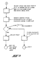
- FIG. 3 is a schematic illustration, in flow chart format, of the control system/method of the present invention.
- control system/control method of the present invention is intended for use in connection with rotational speed sensor assemblies of the type typically utilized to provide input signals to the controllers (CPUs) of vehicular automated drivetrain and/or braking systems.
- controllers CPUs
- Vehicular ABS and automated drivetrain systems are well known in the prior art and examples thereof may be seen by reference to U.S. Patent Nos. 3,920,284; 3,929 382; 4,168,866; 4,478,840; 4,818,035; 4,863,221; 4,361,060; 4,527,447; 4,643,048 and 4,860,861, the disclosures of all of which are hereby incorporated herein by reference.
- Speed sensor assemblies for providing input signals to control units are well known in the prior art as may be seen by reference to above-mentioned U.S. Patent Nos. RE 30522; 3,961,215; 4,862,025; 4,862,028 and 4,893,075.
- speed sensor assemblies 10 include a toothed ferromagnetic rotor 12 which is keyed to a monitored shaft 14 for rotation therewith and a stator or sensor member 16 rotationally fixed relative to a vehicle component 18 for providing signals indicative of the rotational speed of the rotor.
- the present invention is particularly well suited for use with toothed rotor type electromagnetic speed sensor assemblies of the type schematically illustrated in Figure 1, the present invention is equally applicable to any type of speed sensor assembly providing an output in the form of pulses the frequency of which is indicative of the rotational speed of the monitored members.
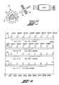
- FIG. 2 is a graphical illustration of the output of a typical pulse type speed sensor assembly and of the use of said pulses to calculate a rotational speed of the monitored shaft 14.
- S (N-1)K/(C N -C O )
- N number of teeth counts per fixed duration time loop (0.010 second for example)
- K a constant
- C N time of last N count
- C O time of first N count.
- K depends upon the number of teeth on the rotor (60 tooth and 100 tooth rotors are typical in ABS systems), gear ratios, tire sizes and the like.
- K 860 cycles per second (HZ) at 100 mph vehicle speed.
- line traces 20 and 22 illustrate proper operation of the sensor assembly 10.
- a tooth pulse should be generated by the sensor assembly every 0.0012 second (1/860).
- the first pulse will be received exactly 0.0012 seconds after the start of the first cycle and thus, assuming substantially constant vehicle speed, eight (8) tooth pulses will be counted during the testing cycle.
- (N-1) will equal seven (7)
- C N -C O will equal 0.0012 - 0.0096
- 0.0084 or one pulse every 0.0012 seconds which corresponds to the calibration of 860 pulses per second equaling 100 mph.
- any wheel acceleration exceeding a reference value of approximately -25 or -30g may be considered indicative of an error.
- (N-1) will equal seven (7)
- C N -C O will equal .0084 resulting in a frequency of tooth pulse of one every .0012 second which, while not allowing sensing of a tooth drop-out problem, will result in an accurate indication of vehicular speed.
- the tooth drop-out will eventually occur other than at the very beginning or the very end of the testing cycle and will allow fault detection thereof.
- N 4
- C N - C O .0072 (.0024 - .0096) which is a pulse every 0.0024 second. If a tooth or pulse is "dropped", N-1 will equal 2, which indicates a pulse every 0.0036 second or a vehicle deceleration of about 75G which will, of course, exceed the reference REF.
- K will equal 1400 KZ at 100 MPH vehicle speed (700 KZ at 50 MPH vehicle speed) and a dropped tooth pulse will result in an apparent vehicle acceleration of about -35g at true 100 MPH and about -38g at true 50 MPH vehicle speeds, both of which will exceed the selected reference.
- the system Upon sensing of a tooth drop-out fault, the system will, preferably, indicate the existence of a fault to the vehicle operator and will take appropriate action in the form of either fail safe or fail soft logic.
- a fail safe logic situation the automated system utilizing the sensor assembly 10 will simply discontinue operation which may render the vehicle inoperative.
- a fail soft situation usually associated with non-vehicle safety related equipment, a fault tolerance logic will be utilized.
- the logic may utilize transmission input shaft speed as a substitute therefor. Fault tolerance logic of this nature may be seen by reference to U.S. Patent No. 4,849,899, the disclosure of which is hereby incorporated by reference.
- a cycle time is selected such that if the true value of N-1 is misread as N-2 or less, then the change or first time derivative of calculated vehicle speed will exceed the predetermined reference value.
- the predetermined reference value is about -20 to -30g which exceeds the maximum vehicle deceleration rate expected in vehicular applications.
Abstract
Description
- The present invention relates to a system/method for detecting faults in the output signals from rotational speed sensors. In particular, the present invention relates to a system/method for detecting faults, particularly "tooth drop-out" type faults, in rotational speed sensors of the type comprising a relatively rotatable toothed rotor which rotates past a rotationally fixed sensor or stator member.
- Rotational speed sensors which utilize a relatively rotatable toothed rotor which rotates past a relatively fixed sensor or the like are well known in the prior art. Examples of such speed sensor assemblies may be seen by reference to U.S. Patent Nos. RE 30,522; 3,961,215; 4,862,025; 4,862,028 and 4,893,075, the disclosures of which are hereby incorporated herein by reference. Such rotational speed sensors are often used in connection with automated vehicular components/systems such as automatic fuel controls, automated transmission systems and/or vehicular anti-lock brake systems (ABS).
- Typically, such rotational speed sensor assemblies are electromagnetic in nature and rely on the alignment of rotor teeth or spaces between rotor teeth rotating past a sensor to complete or break, respectively, a magnetic flux path to produce a digital or analog signal indicative of the rotational speed of the rotor.
- While systems utilizing such rotational speed sensors are well known and widely used, they are not totally satisfactory as misalignments, jolts, damaged rotors or other causes may cause one or more tooth or pulse per measuring cycle not to be properly counted, i.e. "tooth drop-out". When this occurs, a false reading can be generated, usually indicating a much lower than actual speed and/or much greater than actual deceleration rate, which false reading if not detected can result in the automated system operating in an undesirable manner.
- In accordance with the present invention, the drawbacks of the prior art have been minimized or overcome by the provision of a fault sensing technique for detecting if a "missed" or "dropped tooth" speed sensor reading has occurred and, if sensed, for going into a "fail safe" or a "fail soft" logic routine.
- The above is accomplished by calculating the currently indicated rotational speed by the relationship
- S =
- a function of (N-1)K/(CN-CO)
- N =
- number of tooth counts or pulses per fixed duration time loop (0.010 sec. for example);
- K =
- a constant;
- CN =
- time of last N count; and
- CO =
- time of first N count.
- If the current change in S, or dS/dt, is greater than a predetermined reference value (REF) selected to represent the greatest expected wheel deceleration, such as -25G to -30G for example, then a single or multiple "tooth drop-out" error is sensed and the system will either shut off ("fail safe") or go into a fault tolerant ("fail soft") mode of operation.
- The time duration of the loop is selected so that a false reading of (N-1) by a single unit will either not effect the calculated value of S or will be detectable (i.e. will cause dS/dt to exceed the reference value REF). Preferably, the fault check logic is preformed prior to any filtering of the sensor input signal.
- Accordingly, it is an object of the present invention to provide a control system/method for detecting "tooth drop-out" type errors in a tooth count type toothed rotor/fixed sensor rotational speed sensor.
- This and other objects and advantages of the present invention will become apparent from a reading of the description of the preferred embodiment taken in connection with the attached drawings.
- Figure 1 is a schematic illustration of a toothed rotor type speed sensor assembly.
- Figure 2 is a graphical illustration of the output signals from a typical prior art rotational speed sensor.
- Figure 3 is a schematic illustration, in flow chart format, of the control system/method of the present invention.
- The control system/control method of the present invention is intended for use in connection with rotational speed sensor assemblies of the type typically utilized to provide input signals to the controllers (CPUs) of vehicular automated drivetrain and/or braking systems. Typically, the greatest possible acceleration and/or deceleration of such wheels is a known value.
- Vehicular ABS and automated drivetrain systems are well known in the prior art and examples thereof may be seen by reference to U.S. Patent Nos. 3,920,284; 3,929 382; 4,168,866; 4,478,840; 4,818,035; 4,863,221; 4,361,060; 4,527,447; 4,643,048 and 4,860,861, the disclosures of all of which are hereby incorporated herein by reference.
- Speed sensor assemblies for providing input signals to control units, usually microprocessor based central processing units, are well known in the prior art as may be seen by reference to above-mentioned U.S. Patent Nos. RE 30522; 3,961,215; 4,862,025; 4,862,028 and 4,893,075. Typically, as may be seen by reference to Figure 1, such speed sensor assemblies 10 include a toothed
ferromagnetic rotor 12 which is keyed to a monitoredshaft 14 for rotation therewith and a stator orsensor member 16 rotationally fixed relative to avehicle component 18 for providing signals indicative of the rotational speed of the rotor. Usually, rotation of one tooth and one tooth space past the stator orsensor 16 will result in the making and then breaking of a magnetic flux path which will result in pulses of increasing and decreasing induced current, the frequency of such pulses or tooth counts being indicative of the rotational speed of the rotor and those members rotating therewith. Of course, the rotor teeth may be replaced by undulations, apertures, etc. - While the present invention is particularly well suited for use with toothed rotor type electromagnetic speed sensor assemblies of the type schematically illustrated in Figure 1, the present invention is equally applicable to any type of speed sensor assembly providing an output in the form of pulses the frequency of which is indicative of the rotational speed of the monitored members.
- Figure 2 is a graphical illustration of the output of a typical pulse type speed sensor assembly and of the use of said pulses to calculate a rotational speed of the monitored
shaft 14. As has been indicated above, the basic relationship or formula for calculating the rotational speed of a monitored member such asshaft 14 is S = (N-1)K/(CN-CO) where: N = number of teeth counts per fixed duration time loop (0.010 second for example); K = a constant; CN = time of last N count; and CO = time of first N count. The constant K depends upon the number of teeth on the rotor (60 tooth and 100 tooth rotors are typical in ABS systems), gear ratios, tire sizes and the like. In the 60 tooth rotor example illustrated in Figure 2, K = 860 cycles per second (HZ) at 100 mph vehicle speed. - Assuming the cycle time of 10/1000th of a second (0.010 second), line traces 20 and 22 illustrate proper operation of the
sensor assembly 10. At 100 mph vehicle speed, with a constant equal to 860 HZ at 100 mph vehicle speed, a tooth pulse should be generated by the sensor assembly every 0.0012 second (1/860). Intrace line 20, the first pulse will be received exactly 0.0012 seconds after the start of the first cycle and thus, assuming substantially constant vehicle speed, eight (8) tooth pulses will be counted during the testing cycle. Accordingly, (N-1) will equal seven (7) and CN-CO will equal 0.0012 - 0.0096, will equal 0.0084 or one pulse every 0.0012 seconds, which corresponds to the calibration of 860 pulses per second equaling 100 mph. Similarly, referring totrace 22 where the first pulse is received at .001 second into the cycle, nine (9) pulses will be received during the 0.010 second measurement cycle, (N-1) will equal eight (8), CN-CO will equal 0.0096 seconds and once again an average pulse frequency of 0.0012 seconds is observed corresponding to the 100 mph at 860 hz calibration. - Referring to trace 23, assuming vehicle speed has remained at a substantially constant 100 mph and that the toothed pulse which should have been sensed at 0.0025 seconds into the measurement cycle has "dropped out", the CPU will calculate a (N-1) = seven (7) with a CN-CO equaling .0096. This will result in a pulse being received on average once every .00137 seconds or a frequency of about 729.93 HZ which would correspond to about a vehicle velocity of 84.9 miles per hour. This translates into a wheel deceleration of about 15.1 mph in 0.010 second which would correspond to a wheel deceleration of approximately -60g which is clearly in excess of expected wheel deceleration.
- In practice, in typical vehicular use, any wheel acceleration exceeding a reference value of approximately -25 or -30g may be considered indicative of an error. In
trace line 24, assuming a substantially constant 100 mph vehicle speed, and a "drop-out" of the tooth pulse which should have been received at approximately .0097 seconds of the test cycle, (N-1) will equal seven (7), and CN-CO will equal .0084 resulting in a frequency of tooth pulse of one every .0012 second which, while not allowing sensing of a tooth drop-out problem, will result in an accurate indication of vehicular speed. Typically, in a situation such as this, the tooth drop-out will eventually occur other than at the very beginning or the very end of the testing cycle and will allow fault detection thereof. - At 50 MPH vehicle speed, assuming conditions similar to those in the example of
trace 20 above, i.e. K = 860 HZ at 100 MPH vehicle speed and a cycle time of 0.010 second, a tooth pulse should be generated, on average, every 0.0024 second (1/430). Thus N will equal 4, N-1 will equal 3 and CN - CO will equal .0072 (.0024 - .0096) which is a pulse every 0.0024 second. If a tooth or pulse is "dropped", N-1 will equal 2, which indicates a pulse every 0.0036 second or a vehicle deceleration of about 75G which will, of course, exceed the reference REF. - In the case of a 100 tooth rotor, K will equal 1400 KZ at 100 MPH vehicle speed (700 KZ at 50 MPH vehicle speed) and a dropped tooth pulse will result in an apparent vehicle acceleration of about -35g at true 100 MPH and about -38g at true 50 MPH vehicle speeds, both of which will exceed the selected reference.
- It is noted that the apparent vehicle acceleration resulting from a "dropped tooth" is generally constant for a given rotor over a large range of true vehicle speeds.
- Upon sensing of a tooth drop-out fault, the system will, preferably, indicate the existence of a fault to the vehicle operator and will take appropriate action in the form of either fail safe or fail soft logic. In a fail safe logic situation, the automated system utilizing the
sensor assembly 10 will simply discontinue operation which may render the vehicle inoperative. In a fail soft situation, usually associated with non-vehicle safety related equipment, a fault tolerance logic will be utilized. Typically, in for example a transmission system, if the failed sensor is an engine speed sensor the logic may utilize transmission input shaft speed as a substitute therefor. Fault tolerance logic of this nature may be seen by reference to U.S. Patent No. 4,849,899, the disclosure of which is hereby incorporated by reference. - It is, of course, important to select the cycle time which is short enough such that, in the range of expected speeds, a reading of (N-1) which is at least one less than true value will result in a value for the change in S or dS/dt exceeding the predetermined reference value (REF). It is also important that the tooth drop-out fault testing occur prior to any filtering of the input signals from
speed sensor assembly 10. - A schematic illustration, in flow chart format, of the control system/method of the present invention may be seen by reference to Figure 3. As discussed above, a cycle time is selected such that if the true value of N-1 is misread as N-2 or less, then the change or first time derivative of calculated vehicle speed will exceed the predetermined reference value. Preferably, the predetermined reference value is about -20 to -30g which exceeds the maximum vehicle deceleration rate expected in vehicular applications. During each cycle the number N of tooth counts is sensed and the value of change or the first time derivative of d((N-1) K/(CN-CO))/dt is calculated and compared to the reference value. If the change or time derivative, which is representative of vehicle acceleration/deceleration, does not indicate a tooth drop-out fault in the output signal from the
sensor assembly 10, the output of the sensor assembly is filtered and then utilized to calculate the vehicular speed by formula S=(N-1)K/CN-CO. If however a toothed drop-out problem is detected, a fault is declared and the system will then default to a fail safe or fail soft logic routine. - Accordingly, it may be seen that a reliable control system/method has been provided for detecting "dropped tooth" type faults in the output signals from toothed rotor type rotational speed sensors.
- Although the present invention has been defined with a certain degree of particularity, it is understood that the preferred embodiment has been described by way of example only in the numerous modifications and rearrangements are possible without departing from the spirit and the scope of the invention is hereinafter claimed.
Claims (11)
- A fault detection method for detecting "dropped pulse type" faults in the output signals from speed sensor assemblies (10) of the type comprising a rotor (12) rotatably associated with the monitored rotatable member (14) and a relatively fixed sensor member (16), said sensor assembly providing an output signal (20, 22, 24, 26) comprising a plurality of pulses having a frequency indicative of the rotational speed (S) of said rotor, the rotational speed calculated as a function of the number of said pulses over a known period of time, said method characterized by:
calculating a value indicative of the rate of change in S;
comparing the absolute value of said value indicative of in the rate of change in S to a reference value (REF) and
if the absolute value of the value indicative of the rate of change of S is greater than said reference value, declaring a fault. - The fault detection method of claim 1 wherein said reference value (REF) is substantially equal to the largest expected possible deceleration rate of the monitored object.
- The control method of claim 2 wherein said cycle time is selected such that if the actual value of (N-1) is sensed as equaling (N-2) or less, then the calculated absolute value of the rate of change in S will be greater than said reference value.
- The control method of claim 3 wherein said calculated absolute value of the rate of change in S is determined by a comparison of the current calculated value for S and the last calculated value for S.
- The control method of claim 3 wherein the calculated value for the rate of change in S is the first derivative of the value of S with respect to time.
- The control method of claims 1, 2, 3, 4 or 5 wherein said function is defined by the relationship S is a function of (N-1)K/(CN-CO) where S = rotational speed of the monitored object; N = number of pulse counts per fixed time duration cycle loop; K = a constant; CN = time of last N count; and CO = time of first N count.
- A fault detection system for detecting "dropped tooth type" faults in the output signals from tooth rotor type speed sensor assemblies (10) of the type comprising a toothed rotor (12) rotatably associated with the monitored rotatable member (14) and a relatively fixed sensor member (16), said sensor assembly providing an output signal (20, 22, 24, 26) comprising a plurality of pulses having a frequency indicative of the rotational speed of said rotor, the rotational speed calculated as a function of the number of said tooth pulses sensed in a given time period, said system characterized by:
means for calculating a value indicative of the rate of change in S;
means for comparing the absolute value of said value indicative of the rate of change in S to a reference value (REF) and if the absolute value of the value indicative of the rate of change of S is greater than said reference value, declaring a fault. - The fault detection system of claim 7 wherein said reference value (REF) is substantially equal to the largest expected possible deceleration rate of the monitored object.
- The control system of claim 8 wherein said cycle time is selected such that if the actual value of (N-1) is sensed as equaling (N-2) or less, then the calculated absolute value of the rate of change in S will be greater than said reference value.
- The control system of claim 9 wherein the calculated value for the rate of change in S is the first derivative of the value of S with respect to time.
- The control system of claims 7, 8, 9 or 10 wherein said function is defined by the relationship S is a function of (N-1)K/(CN-CO) where S = rotational speed of the monitored object; N = number of tooth pulse counts per fixed time duration cycle loop; K = a constant; CN = time of last N count; and CO = time of first N count,
Applications Claiming Priority (2)
| Application Number | Priority Date | Filing Date | Title |
|---|---|---|---|
| US07/528,521 US5095269A (en) | 1990-05-25 | 1990-05-25 | Speed sensor fault detection system and method |
| US528521 | 1990-05-25 |
Publications (2)
| Publication Number | Publication Date |
|---|---|
| EP0458121A1 true EP0458121A1 (en) | 1991-11-27 |
| EP0458121B1 EP0458121B1 (en) | 1995-07-19 |
Family
ID=24106017
Family Applications (1)
| Application Number | Title | Priority Date | Filing Date |
|---|---|---|---|
| EP91107364A Expired - Lifetime EP0458121B1 (en) | 1990-05-25 | 1991-05-07 | Speed sensor fault detection system and method |
Country Status (8)
| Country | Link |
|---|---|
| US (1) | US5095269A (en) |
| EP (1) | EP0458121B1 (en) |
| JP (1) | JPH0674961A (en) |
| KR (1) | KR960012785B1 (en) |
| AU (1) | AU636274B2 (en) |
| BR (1) | BR9102149A (en) |
| CA (1) | CA2043238C (en) |
| DE (1) | DE69111300T2 (en) |
Cited By (4)
| Publication number | Priority date | Publication date | Assignee | Title |
|---|---|---|---|---|
| DE19602359A1 (en) * | 1996-01-24 | 1997-07-31 | Teves Gmbh Alfred | Method and circuit arrangement for monitoring a speed sensor |
| DE19749791A1 (en) * | 1997-11-11 | 1999-05-12 | Wabco Gmbh | Evaluation method for an output signal of a sensor device scanning a cyclical movement |
| WO2007033914A1 (en) * | 2005-09-22 | 2007-03-29 | Siemens Vdo Automotive Ag | Method for monitoring a turboshaft rotational speed |
| US8886471B2 (en) | 2008-06-26 | 2014-11-11 | Infineon Technologies Ag | Rotation sensing method and system |
Families Citing this family (10)
| Publication number | Priority date | Publication date | Assignee | Title |
|---|---|---|---|---|
| US5343396A (en) * | 1992-04-29 | 1994-08-30 | Youngblood Richard J | Sensor malfunction detection |
| US5264789A (en) * | 1992-07-27 | 1993-11-23 | Eaton Corporation | Method of determining the direction of rotation of a member using a rotor having a predetermined pattern of exciter surfaces |
| DE19622462B4 (en) * | 1996-06-05 | 2004-12-09 | Robert Bosch Gmbh | Fault detection method and device |
| DE10162599B4 (en) * | 2001-12-20 | 2020-02-20 | Robert Bosch Gmbh | Method and device for monitoring speed sensors for missing teeth |
| JP2008261883A (en) * | 2003-01-10 | 2008-10-30 | Toyota Motor Corp | Vehicle and diagnosis device |
| TW200821460A (en) * | 2006-07-11 | 2008-05-16 | Yamaha Motor Co Ltd | Internal combustion engine controlling apparatus and automotive vehicle incorporating the same |
| KR101134908B1 (en) * | 2006-09-08 | 2012-04-17 | 주식회사 만도 | Method of fail detection of wheel speed sensor |
| FR2987085B1 (en) * | 2012-02-20 | 2014-03-21 | Snecma | METHOD FOR SECURING THE OPERATION OF A TURBOMACHINE |
| DE102015212944A1 (en) * | 2015-07-10 | 2017-01-12 | Continental Automotive Gmbh | Method and device for determining rotational angular velocities and / or rotational angular positions of vehicle wheels of a motor vehicle, as well as for locating the installation positions of wheel units arranged on the vehicle wheels |
| GB201714978D0 (en) * | 2017-09-18 | 2017-11-01 | Trw Ltd | Detecting misalignment |
Citations (3)
| Publication number | Priority date | Publication date | Assignee | Title |
|---|---|---|---|---|
| US3908116A (en) * | 1974-08-16 | 1975-09-23 | Rockwell International Corp | Digital data filter |
| DE3426663A1 (en) * | 1983-07-20 | 1985-01-31 | Nippondenso Co., Ltd., Kariya, Aichi | DEVICE, SENSITIVE TO FAULTS, FOR DETECTING WHEEL SPEEDS AND WHEEL ACCELERATIONS AND METHOD THEREFOR |
| US4849899A (en) * | 1986-04-07 | 1989-07-18 | Eaton Corporation | Method for controlling AMT system including speed sensor signal fault detection and tolerance |
Family Cites Families (14)
| Publication number | Priority date | Publication date | Assignee | Title |
|---|---|---|---|---|
| US3961215A (en) * | 1973-12-26 | 1976-06-01 | Eaton Corporation | Rotor for wheel speed sensor assembly |
| US3920284A (en) * | 1974-05-10 | 1975-11-18 | Eaton Corp | Monitoring circuitry for a skid control system |
| US3929382A (en) * | 1974-05-10 | 1975-12-30 | Eaton Corp | Skid control system |
| DE2644646C2 (en) * | 1976-10-02 | 1983-04-07 | Robert Bosch Gmbh, 7000 Stuttgart | Device for detecting one or more missing pulses in an otherwise regular pulse train |
| US4168866A (en) * | 1977-09-09 | 1979-09-25 | Eaton Corporation | Anti-wheel lock system |
| JPS59210374A (en) * | 1983-05-16 | 1984-11-29 | Nissan Motor Co Ltd | Wheel speed arithmetic device |
| GB8605152D0 (en) * | 1986-03-03 | 1986-04-09 | Hughes Ltd Stewart | Digital tachometer |
| US4768840A (en) * | 1987-04-27 | 1988-09-06 | Eaton Corporation | Brake control system and method |
| US4818035A (en) * | 1987-04-27 | 1989-04-04 | Eaton Corporation | Tractor-trailer brake control system |
| US4835467A (en) * | 1988-01-25 | 1989-05-30 | General Motors Corporation | Wheel speed sensor |
| US4863221A (en) * | 1988-08-18 | 1989-09-05 | Eaton Corporation | Tandem drive axle anti-lock brake system |
| US4862028A (en) * | 1988-08-25 | 1989-08-29 | Eaton Corporation | Exciter rotor assembly |
| US4862025A (en) * | 1988-08-25 | 1989-08-29 | Eaton Corporation | Dual speed sensor pickup assembly |
| US4893075A (en) * | 1988-08-29 | 1990-01-09 | Eaton Corporation | Dual speed sensor pickup assembly with anti-cross talk coils |
-
1990
- 1990-05-25 US US07/528,521 patent/US5095269A/en not_active Expired - Fee Related
-
1991
- 1991-05-07 DE DE69111300T patent/DE69111300T2/en not_active Expired - Fee Related
- 1991-05-07 EP EP91107364A patent/EP0458121B1/en not_active Expired - Lifetime
- 1991-05-14 KR KR1019910007787A patent/KR960012785B1/en not_active IP Right Cessation
- 1991-05-16 AU AU77090/91A patent/AU636274B2/en not_active Ceased
- 1991-05-21 BR BR919102149A patent/BR9102149A/en not_active IP Right Cessation
- 1991-05-24 CA CA002043238A patent/CA2043238C/en not_active Expired - Fee Related
- 1991-05-24 JP JP3149907A patent/JPH0674961A/en active Pending
Patent Citations (3)
| Publication number | Priority date | Publication date | Assignee | Title |
|---|---|---|---|---|
| US3908116A (en) * | 1974-08-16 | 1975-09-23 | Rockwell International Corp | Digital data filter |
| DE3426663A1 (en) * | 1983-07-20 | 1985-01-31 | Nippondenso Co., Ltd., Kariya, Aichi | DEVICE, SENSITIVE TO FAULTS, FOR DETECTING WHEEL SPEEDS AND WHEEL ACCELERATIONS AND METHOD THEREFOR |
| US4849899A (en) * | 1986-04-07 | 1989-07-18 | Eaton Corporation | Method for controlling AMT system including speed sensor signal fault detection and tolerance |
Non-Patent Citations (1)
| Title |
|---|
| PATENT ABSTRACTS OF JAPAN, vol. 10, no. 215 (P-481)[2271], 26th July 1986; & JP-A-61 54 456 (TOYODA AUTOM LOOM WORKS LTD) 18-03-1986 * |
Cited By (7)
| Publication number | Priority date | Publication date | Assignee | Title |
|---|---|---|---|---|
| DE19602359A1 (en) * | 1996-01-24 | 1997-07-31 | Teves Gmbh Alfred | Method and circuit arrangement for monitoring a speed sensor |
| DE19749791A1 (en) * | 1997-11-11 | 1999-05-12 | Wabco Gmbh | Evaluation method for an output signal of a sensor device scanning a cyclical movement |
| WO2007033914A1 (en) * | 2005-09-22 | 2007-03-29 | Siemens Vdo Automotive Ag | Method for monitoring a turboshaft rotational speed |
| DE102005045457A1 (en) * | 2005-09-22 | 2007-04-05 | Siemens Ag | Method for monitoring the speed of a turbo shaft |
| DE102005045457B4 (en) * | 2005-09-22 | 2014-10-02 | Continental Automotive Gmbh | Method for monitoring the speed of a turbo shaft |
| US8886471B2 (en) | 2008-06-26 | 2014-11-11 | Infineon Technologies Ag | Rotation sensing method and system |
| US9869568B2 (en) | 2008-06-26 | 2018-01-16 | Infineon Technologies Ag | Sensing method and system for correcting an input waveform from a coded wheel |
Also Published As
| Publication number | Publication date |
|---|---|
| US5095269A (en) | 1992-03-10 |
| JPH0674961A (en) | 1994-03-18 |
| BR9102149A (en) | 1991-12-24 |
| AU7709091A (en) | 1991-11-28 |
| CA2043238A1 (en) | 1991-11-26 |
| CA2043238C (en) | 1997-11-18 |
| DE69111300D1 (en) | 1995-08-24 |
| DE69111300T2 (en) | 1996-04-04 |
| KR960012785B1 (en) | 1996-09-24 |
| AU636274B2 (en) | 1993-04-22 |
| KR910020444A (en) | 1991-12-20 |
| EP0458121B1 (en) | 1995-07-19 |
Similar Documents
| Publication | Publication Date | Title |
|---|---|---|
| US5095269A (en) | Speed sensor fault detection system and method | |
| EP1155330B1 (en) | Method for recognition of signal errors | |
| KR100403228B1 (en) | Error recognition method in rotation speed sensor | |
| US4347569A (en) | Wheel slip system | |
| US4495578A (en) | Microprocessor based over/under speed governor | |
| US6204658B1 (en) | Method for evaluating an output signal of a rotational sensing device | |
| US6502025B1 (en) | Relative steering angle sensor diagnostic for momentary signal dropout | |
| JP3591191B2 (en) | Detection means abnormality determination device | |
| CN1280632C (en) | Magnetic rotation detector, relative vehicle control device and method for judging abnormal of roter | |
| EP0607690A1 (en) | Method and device for detecting pneumatic abnormalities of tyre | |
| EP0581470A1 (en) | Method of determining the direction of rotation of a member | |
| EP0567862B1 (en) | Sensor malfunction detection | |
| JPH11508212A (en) | Device for detecting electromagnetic interference noise | |
| US20140009141A1 (en) | Method for Operating a Speed Sensing Device | |
| US6525529B2 (en) | Method and apparatus for detecting broken teeth in a pulse signal of a wheel speed sensor for an ABS vehicle stabilization system | |
| CN112519835B (en) | Train speed determination method and device, electronic equipment and readable storage medium | |
| HU214278B (en) | Method and safety circuit arrangement for supervising the proper operation of vehicle brake systems equipped with abs electronics | |
| CN111380708A (en) | Train axle locking fault diagnosis method and train axle locking fault diagnosis system | |
| JPS6358167A (en) | Trouble detector for rotation sensor | |
| CA2059452C (en) | Speed sensor failure detection method and apparatus for an overspeed protection system | |
| US6485114B2 (en) | Sensor error detection in a dual sensor system | |
| US20190066405A1 (en) | Method and system for detecting a road impact event and for diagnosing abnormalities in chassis components | |
| US5727855A (en) | Anti-locking control system | |
| CN110343844B (en) | Method and device for controlling loop sleeve amount of continuous annealing unit | |
| KR100413254B1 (en) | How to determine abnormal condition of wheel speed sensor |
Legal Events
| Date | Code | Title | Description |
|---|---|---|---|
| PUAI | Public reference made under article 153(3) epc to a published international application that has entered the european phase |
Free format text: ORIGINAL CODE: 0009012 |
|
| AK | Designated contracting states |
Kind code of ref document: A1 Designated state(s): DE FR GB IT SE |
|
| 17P | Request for examination filed |
Effective date: 19920123 |
|
| 17Q | First examination report despatched |
Effective date: 19930603 |
|
| GRAA | (expected) grant |
Free format text: ORIGINAL CODE: 0009210 |
|
| AK | Designated contracting states |
Kind code of ref document: B1 Designated state(s): DE FR GB IT SE |
|
| REF | Corresponds to: |
Ref document number: 69111300 Country of ref document: DE Date of ref document: 19950824 |
|
| ET | Fr: translation filed | ||
| ITF | It: translation for a ep patent filed |
Owner name: ING. C. GREGORJ S.P.A. |
|
| PLBE | No opposition filed within time limit |
Free format text: ORIGINAL CODE: 0009261 |
|
| STAA | Information on the status of an ep patent application or granted ep patent |
Free format text: STATUS: NO OPPOSITION FILED WITHIN TIME LIMIT |
|
| 26N | No opposition filed | ||
| PGFP | Annual fee paid to national office [announced via postgrant information from national office to epo] |
Ref country code: FR Payment date: 19980408 Year of fee payment: 8 |
|
| PGFP | Annual fee paid to national office [announced via postgrant information from national office to epo] |
Ref country code: GB Payment date: 19980417 Year of fee payment: 8 |
|
| PGFP | Annual fee paid to national office [announced via postgrant information from national office to epo] |
Ref country code: SE Payment date: 19980506 Year of fee payment: 8 |
|
| PGFP | Annual fee paid to national office [announced via postgrant information from national office to epo] |
Ref country code: DE Payment date: 19980529 Year of fee payment: 8 |
|
| PG25 | Lapsed in a contracting state [announced via postgrant information from national office to epo] |
Ref country code: GB Free format text: LAPSE BECAUSE OF NON-PAYMENT OF DUE FEES Effective date: 19990507 |
|
| PG25 | Lapsed in a contracting state [announced via postgrant information from national office to epo] |
Ref country code: SE Free format text: LAPSE BECAUSE OF NON-PAYMENT OF DUE FEES Effective date: 19990508 |
|
| GBPC | Gb: european patent ceased through non-payment of renewal fee |
Effective date: 19990507 |
|
| EUG | Se: european patent has lapsed |
Ref document number: 91107364.1 |
|
| PG25 | Lapsed in a contracting state [announced via postgrant information from national office to epo] |
Ref country code: FR Free format text: LAPSE BECAUSE OF NON-PAYMENT OF DUE FEES Effective date: 20000131 |
|
| PG25 | Lapsed in a contracting state [announced via postgrant information from national office to epo] |
Ref country code: DE Free format text: LAPSE BECAUSE OF NON-PAYMENT OF DUE FEES Effective date: 20000301 |
|
| REG | Reference to a national code |
Ref country code: FR Ref legal event code: ST |
|
| PG25 | Lapsed in a contracting state [announced via postgrant information from national office to epo] |
Ref country code: IT Free format text: LAPSE BECAUSE OF NON-PAYMENT OF DUE FEES;WARNING: LAPSES OF ITALIAN PATENTS WITH EFFECTIVE DATE BEFORE 2007 MAY HAVE OCCURRED AT ANY TIME BEFORE 2007. THE CORRECT EFFECTIVE DATE MAY BE DIFFERENT FROM THE ONE RECORDED. Effective date: 20050507 |