US9869568B2 - Sensing method and system for correcting an input waveform from a coded wheel - Google Patents
Sensing method and system for correcting an input waveform from a coded wheel Download PDFInfo
- Publication number
- US9869568B2 US9869568B2 US14/538,431 US201414538431A US9869568B2 US 9869568 B2 US9869568 B2 US 9869568B2 US 201414538431 A US201414538431 A US 201414538431A US 9869568 B2 US9869568 B2 US 9869568B2
- Authority
- US
- United States
- Prior art keywords
- waveform
- input waveform
- signal
- sensor
- stored
- Prior art date
- Legal status (The legal status is an assumption and is not a legal conclusion. Google has not performed a legal analysis and makes no representation as to the accuracy of the status listed.)
- Active, expires
Links
Images


Classifications
-
- G—PHYSICS
- G01—MEASURING; TESTING
- G01D—MEASURING NOT SPECIALLY ADAPTED FOR A SPECIFIC VARIABLE; ARRANGEMENTS FOR MEASURING TWO OR MORE VARIABLES NOT COVERED IN A SINGLE OTHER SUBCLASS; TARIFF METERING APPARATUS; MEASURING OR TESTING NOT OTHERWISE PROVIDED FOR
- G01D18/00—Testing or calibrating apparatus or arrangements provided for in groups G01D1/00 - G01D15/00
- G01D18/001—Calibrating encoders
-
- G—PHYSICS
- G01—MEASURING; TESTING
- G01D—MEASURING NOT SPECIALLY ADAPTED FOR A SPECIFIC VARIABLE; ARRANGEMENTS FOR MEASURING TWO OR MORE VARIABLES NOT COVERED IN A SINGLE OTHER SUBCLASS; TARIFF METERING APPARATUS; MEASURING OR TESTING NOT OTHERWISE PROVIDED FOR
- G01D5/00—Mechanical means for transferring the output of a sensing member; Means for converting the output of a sensing member to another variable where the form or nature of the sensing member does not constrain the means for converting; Transducers not specially adapted for a specific variable
- G01D5/12—Mechanical means for transferring the output of a sensing member; Means for converting the output of a sensing member to another variable where the form or nature of the sensing member does not constrain the means for converting; Transducers not specially adapted for a specific variable using electric or magnetic means
-
- G01D5/24452—
-
- G—PHYSICS
- G01—MEASURING; TESTING
- G01D—MEASURING NOT SPECIALLY ADAPTED FOR A SPECIFIC VARIABLE; ARRANGEMENTS FOR MEASURING TWO OR MORE VARIABLES NOT COVERED IN A SINGLE OTHER SUBCLASS; TARIFF METERING APPARATUS; MEASURING OR TESTING NOT OTHERWISE PROVIDED FOR
- G01D5/00—Mechanical means for transferring the output of a sensing member; Means for converting the output of a sensing member to another variable where the form or nature of the sensing member does not constrain the means for converting; Transducers not specially adapted for a specific variable
- G01D5/12—Mechanical means for transferring the output of a sensing member; Means for converting the output of a sensing member to another variable where the form or nature of the sensing member does not constrain the means for converting; Transducers not specially adapted for a specific variable using electric or magnetic means
- G01D5/244—Mechanical means for transferring the output of a sensing member; Means for converting the output of a sensing member to another variable where the form or nature of the sensing member does not constrain the means for converting; Transducers not specially adapted for a specific variable using electric or magnetic means influencing characteristics of pulses or pulse trains; generating pulses or pulse trains
- G01D5/24457—Failure detection
- G01D5/24461—Failure detection by redundancy or plausibility
-
- G—PHYSICS
- G01—MEASURING; TESTING
- G01D—MEASURING NOT SPECIALLY ADAPTED FOR A SPECIFIC VARIABLE; ARRANGEMENTS FOR MEASURING TWO OR MORE VARIABLES NOT COVERED IN A SINGLE OTHER SUBCLASS; TARIFF METERING APPARATUS; MEASURING OR TESTING NOT OTHERWISE PROVIDED FOR
- G01D5/00—Mechanical means for transferring the output of a sensing member; Means for converting the output of a sensing member to another variable where the form or nature of the sensing member does not constrain the means for converting; Transducers not specially adapted for a specific variable
- G01D5/12—Mechanical means for transferring the output of a sensing member; Means for converting the output of a sensing member to another variable where the form or nature of the sensing member does not constrain the means for converting; Transducers not specially adapted for a specific variable using electric or magnetic means
- G01D5/244—Mechanical means for transferring the output of a sensing member; Means for converting the output of a sensing member to another variable where the form or nature of the sensing member does not constrain the means for converting; Transducers not specially adapted for a specific variable using electric or magnetic means influencing characteristics of pulses or pulse trains; generating pulses or pulse trains
- G01D5/24471—Error correction
- G01D5/2448—Correction of gain, threshold, offset or phase control
-
- G—PHYSICS
- G01—MEASURING; TESTING
- G01D—MEASURING NOT SPECIALLY ADAPTED FOR A SPECIFIC VARIABLE; ARRANGEMENTS FOR MEASURING TWO OR MORE VARIABLES NOT COVERED IN A SINGLE OTHER SUBCLASS; TARIFF METERING APPARATUS; MEASURING OR TESTING NOT OTHERWISE PROVIDED FOR
- G01D5/00—Mechanical means for transferring the output of a sensing member; Means for converting the output of a sensing member to another variable where the form or nature of the sensing member does not constrain the means for converting; Transducers not specially adapted for a specific variable
- G01D5/12—Mechanical means for transferring the output of a sensing member; Means for converting the output of a sensing member to another variable where the form or nature of the sensing member does not constrain the means for converting; Transducers not specially adapted for a specific variable using electric or magnetic means
- G01D5/244—Mechanical means for transferring the output of a sensing member; Means for converting the output of a sensing member to another variable where the form or nature of the sensing member does not constrain the means for converting; Transducers not specially adapted for a specific variable using electric or magnetic means influencing characteristics of pulses or pulse trains; generating pulses or pulse trains
- G01D5/24471—Error correction
- G01D5/24485—Error correction using other sensors
-
- G—PHYSICS
- G01—MEASURING; TESTING
- G01P—MEASURING LINEAR OR ANGULAR SPEED, ACCELERATION, DECELERATION, OR SHOCK; INDICATING PRESENCE, ABSENCE, OR DIRECTION, OF MOVEMENT
- G01P3/00—Measuring linear or angular speed; Measuring differences of linear or angular speeds
- G01P3/42—Devices characterised by the use of electric or magnetic means
- G01P3/44—Devices characterised by the use of electric or magnetic means for measuring angular speed
- G01P3/48—Devices characterised by the use of electric or magnetic means for measuring angular speed by measuring frequency of generated current or voltage
- G01P3/481—Devices characterised by the use of electric or magnetic means for measuring angular speed by measuring frequency of generated current or voltage of pulse signals
- G01P3/487—Devices characterised by the use of electric or magnetic means for measuring angular speed by measuring frequency of generated current or voltage of pulse signals delivered by rotating magnets
-
- G—PHYSICS
- G01—MEASURING; TESTING
- G01P—MEASURING LINEAR OR ANGULAR SPEED, ACCELERATION, DECELERATION, OR SHOCK; INDICATING PRESENCE, ABSENCE, OR DIRECTION, OF MOVEMENT
- G01P3/00—Measuring linear or angular speed; Measuring differences of linear or angular speeds
- G01P3/42—Devices characterised by the use of electric or magnetic means
- G01P3/44—Devices characterised by the use of electric or magnetic means for measuring angular speed
- G01P3/48—Devices characterised by the use of electric or magnetic means for measuring angular speed by measuring frequency of generated current or voltage
- G01P3/481—Devices characterised by the use of electric or magnetic means for measuring angular speed by measuring frequency of generated current or voltage of pulse signals
- G01P3/489—Digital circuits therefor
Definitions
- a magnetic sensor typically includes a rotatable element and a magnetic field sensor that is stationary relative to the rotatable element.
- the rotatable element defines teeth or is magnetically coded around its edge, and as the toothed or magnetically patterned regions pass the sensor a magnetic field is induced.
- the normal component of the induced field at the position of the sensor has a sinusoidal-like shape.
- the magnetic field sensor element (for example, Hall-effect sensor, Giant Magneto Resistance (GMR) sensor, etc.) converts the applied magnetic field into a proportional electrical signal.
- Signal processing such as zero-crossing detection, is used to convert the sinusoidal-like signal into a binary sequence that is a digital representation of the pattern on the wheel. Knowing the pattern, the rotational speed and angular position can be determined from this binary signal.
- ABS automotive antilock brake systems
- a coded wheel is configured to generate a signal that varies with rotation of the coded wheel.
- a sensor is configured to sense the varying signal and output a corresponding signal.
- a correction module is configured to receive the signal output by the sensor and compare the received signal to a stored signal and detect a defect of the coded wheel in response to the comparison.
- FIG. 1A is a schematic diagram illustrating an embodiment of a sensing system.
- FIG. 1B is a schematic diagram illustrating another embodiment of a sensing system.
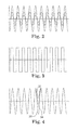
- FIG. 2 illustrates the normal component of a magnetic field with a periodically coded magnet wheel.
- FIG. 3 illustrates a digitized version of the signal illustrated in FIG. 2 .
- FIG. 4 illustrates the normal component of a magnetic field generated by a coded wheel having defects.
- FIG. 5 illustrates digitized versions of two of the signals illustrated in FIG. 4 .
- FIG. 6 illustrates a digitized version of one of the signals illustrated in FIG. 4
- FIG. 7 is a flow diagram illustrating an embodiment of a rotation sensing method.
- FIG. 8 illustrates an embodiment of a signal correction process.
- FIG. 9 illustrates another embodiment of a signal correction process.
- FIG. 1A is a schematic diagram illustrating an embodiment of a sensor system 1 including a coded wheel 2 and a sensor 4 .
- the coded wheel 2 includes a magnetic pattern 10 situated about the periphery of the wheel 2 .
- the sensor 4 is a magnetic sensor, so that when the wheel 2 rotates relative to the sensor 4 , a magnetic field is induced that varies with rotation of the wheel 2 .
- the normal component of the induced field at the position of the sensor 4 has a sinusoidal-like shape.
- the sensor 4 converts the sensed magnetic field into an electrical signal that is received by a correction module 20 .
- the correction module 20 typically includes a suitable processing device, such as a microprocessor, digital signal processor (DSP), application-specific integrated circuit (ASIC), etc. Moreover, in some embodiments, the correction module 20 is integral to the sensor 4 (implemented on a single chip), and in other embodiments it is separate from the sensor 4 .
- a suitable processing device such as a microprocessor, digital signal processor (DSP), application-specific integrated circuit (ASIC), etc.
- DSP digital signal processor
- ASIC application-specific integrated circuit
- FIG. 1B illustrates another embodiment of the sensing system 1 , where the coded wheel 2 defines teeth 12 about the periphery of the wheel 2 and a permanent magnet 14 is situated behind the sensor 4 . As the toothed wheel 2 rotates relative to the sensor, the teeth cause variations in the magnetic field, which is sensed by the sensor 4 and converted to an electrical signal received by the processor 20 .
- the pattern of the magnetic pattern 10 or teeth 12 can be different from application to application. For example, for speed measurements such as would be used for ABS applications, a periodic north south coding is used. For camshaft applications, a non-periodic coding is used. In other embodiments, other types of sensors are used, such as capacitive, inductive, optical, inductive, etc.
- the type of coding on the wheel 2 varies accordingly. For instance, in the case of a capacitive sensor, the pattern 10 could be a conductive pattern that causes capacitance to vary as the wheel 2 rotates relative to the sensor 4 , or in the case of an optical sensor, the pattern 10 could include varying light and dark areas.
- FIG. 2 illustrates the normal component of the magnetic field at the sensor 4 with a periodically coded magnet wheel 2 .
- the magnetic field has a generally sinusoidal pattern resulting from rotation of the wheel 2 .
- the signal output by the sensor 4 is proportional to the magnetic field.
- the signal is digitized by the sensor 4 or the processor 20 by sensing the zero-crossing of the signal.
- FIG. 3 illustrates an example of a digitized signal generated from a wheel 2 having north-south magnetic coding, wherein the sensor 4 and/or processor 20 measure and analyze the frequency or pulse-width of the resulting square wave signal, for example.
- the speed of the wheel can be measured by measuring the pulse width of the digital signal. Variations of the revolution speed cause variations of the pulse width.
- Factors such as contamination, aging, manufacturing variation, etc. can cause variation in the magnetization of the poles of the coded wheel 2 . Some individual poles can be more strongly magnetized than others. Further, these factors can result in partly or completely short circuiting individual magnetic poles.
- FIG. 4 illustrates various signals generated by the normal component of a magnetic field at the sensor 4 .
- the signal resulting from an ideal magnet wheel is illustrated by curve 30 .
- Curves 32 and 34 illustrate a signal resulting from a wheel having a partly demagnetized pole and a pole that is short circuited by iron splinters, respectively. The amplitude of curves 32 and 34 at the position of the defective poles is reduced, and curve 32 does not exhibit a zero-crossing.
- FIG. 5 illustrates digitized versions of the signals 30 a and 34 a resulting from a zero-crossing detection process.
- the wheel 2 is turning at a constant speed, which is reflected by the constant pulse-width of curve 30 a (no defects).
- curve 34 a With curve 34 a , however, the varying amplitude of the sinusoidal signal 34 shown in FIG. 4 results in a corresponding change in the zero-crossing at the location of the defective pole, thus changing the pulse-width/frequency of the digitized signal 34 a.
- FIG. 6 illustrates a digitized version 32 a of curve 32 .
- the curve 32 does not have a zero-crossing in the area of the defective pole due to a defect in the coded wheel 2 .
- This is results in a “skipped” pulse in the corresponding digitized version 32 a illustrated in FIG. 6 , changing the pulse-width/frequency of the signal. Therefore, even though the wheel 2 is turning at a constant speed, the frequency changes demonstrated by signals 32 a and 34 a would be interpreted by the processor 20 as a speed change.
- the sensing system 1 is used in an ABS application, for example, this could result in unnecessarily activating the ABS system. In this situation, the activated ABS system would vary the (constant) wheel speed.
- Typical defects (manufacturing, aging, etc.) in the pattern 10 or teeth 12 of the wheel 2 are constant for long periods of time, or at least for several revolutions. If the wheel 2 is rotating at a constant speed, the resulting field and corresponding signal output by the sensor 4 is consistent and repeats itself after each full revolution of the wheel 2 . Assuming a constant rotation speed, the signal output by the sensor 4 representing a revolution of the wheel 2 , or a portion of a revolution, will match a stored signal representing a previous rotation or corresponding portion of a rotation.
- FIG. 7 is a flow diagram generally illustrating an embodiment of a disclosed rotation sensing method.
- the coded wheel 2 is rotated, which as discussed above results in a signal representing rotation of the wheel 2 that is output by the sensor 4 and received by the correction module 20 (block 102 ).
- the received signal is compared to one or more stored signals.
- the conversion module 20 has access to a memory that stores a signal representing an earlier rotation or portion of a rotation of the coded wheel 2 . For example, signals representing one or more of the rotations immediately preceding the current rotation can be stored.
- the magnetic pattern on the wheel 2 can be known by the correction module 20 and pre-stored in memory, or “learned” during startup, for example.
- the received signal includes an anomaly, such as a change in frequency, and the stored signal has the same anomaly, it can be assumed that the anomaly is due to a defect in the coded wheel 2 , rather than a change in rotation of the wheel 2 .
- a defect in the coded wheel can be detected in response to the comparison of the received signal with the stored signal.
- the received signal is corrected by the correction module 20 .
- the sensor 4 outputs an analog signal that is converted to a binary signal by a suitable analog-to-digital conversion process, such as zero-crossing detection in the continuous time or discrete time domain.
- a suitable analog-to-digital conversion process such as zero-crossing detection in the continuous time or discrete time domain.
- the binary signal is then stored and compared, and upon detection of a defect, the binary signal is corrected.
- FIG. 8 conceptually illustrates such a process, where the sensor signal is digitized and corrected.
- the coded wheel 2 rotates, generating a varying magnetic field 32 that is output by the sensor.
- the analog signal 32 is digitized, for example by a zero-crossing detector 22 , which outputs the digital signal 32 a .
- the amplitude of the analog signal 32 varies due to a defect in the coded wheel 2 , resulting in a frequency variation in the digital signal 32 a .
- the received digital signal 32 a is received by the correction module 20 , and the received signal 32 a is compared to one or more stored signals as illustrated in block 104 of FIG. 7 . If the comparison determines that the stored signal has the same frequency pattern as the received signal 32 a , it is assumed this is due to a defect in the coded wheel 2 .
- the correction module corrects the signal 32 a (effectively adding the “missing” pulse), and outputs a corrected signal 32 b.
- the analog signal 32 is stored and analyzed, resulting in detection of defects and signal correction.
- FIG. 9 conceptually illustrates such an embodiment, where the analog sensor signal 32 is received by the correction module, which performs the signal comparison/analysis and directly outputs the corrected digital signal 32 b . Variations caused by aging of the magnetic wheel, for example, may be better detected in the analog domain.
- parameters such as the amplitude of the waveform, gradient, peak value, etc. can be used to detect defects.
- the analog values can be stored in the analog domain using capacitors or similar solutions.
- the analog signal can also be converted into the digital domain, and digital signal processing can be used to evaluate the signal.
- FIG. 8 conceptually illustrates such an embodiment where a single bit analog-to digital converter (ADC) (i.e. zero crossing detection) is used to convert the analog signal into a binary signal.
- ADC analog-to digital converter
- the signal 32 a has a higher number of different quantization levels and therefore the same parameters as described above can be used to detect defects.
- Embodiments are envisioned where a physical or mathematical model of the sensor signal is generated and used for analysis. Using a model, additional information about the arrangement can be determined. For example, a physical model can describe the magnetic field as a function of the magnetic strength and pattern. The parameter values can be estimated adaptively. It is also possible to work in the frequency domain. The frequency components of the waveform can be measured and evaluated. Frequency measurements can be done in the analog or digital domain (for example, using a FFT).
- Additional output signals can be provided by the correction module 20 .
- information such as whether the actual output signal was corrected, if some defect on the pole wheel was detected, can be output.
- the output signal is a binary signal which delivers the information as to whether there is a defect in the coded wheel 2 or not.
- the output signal can provide more precise information about the defects, for example, the particular angular position(s) of defects, changes in the magnetic strength of a pole, etc.
- the correction module 20 can be configured to detect some errors, for example, defects on the pole wheel, but without correcting them. It is also possible to correct the output signal only a predetermined number of times, for example, two times per revolution. If more than a predetermined number of errors are detected, the correction algorithm may be disabled. Or, in some embodiments, the output signal is corrected only if more then a predetermined number of errors is detected.
- the correction module 20 is employed with coded pole wheels 2 having a non-periodic pattern.
- coded pole wheels 2 having a non-periodic pattern is employed with coded pole wheels 2 having a non-periodic pattern.
- One example is a pole wheel with one magnet which is longer as the other ones.
- a more complex magnetic pattern can be used.
- variations of the air gap between sensor element and pole wheel cause a displacement of the zero-crossing position. However, typically such a zero-crossing displacement would be constant over a few revolutions, thus allowing use of the disclosed method.
- a toothed wheel 3 made of a magnetic material such as iron is used and a permanent magnet 14 is mounted at a fixed angular position to generate a constant magnetic field.
- the magnetic field at the sensor 4 has a sinusoidal-like waveform, similar to the waveforms shown in FIG. 4 , though with an additional DC component. Due to the DC component the magnetic signal has no zero-crossings.
- the sensor 4 and/or correction module 20 is configured to remove or otherwise compensate for the DC component, for example, using a high pass filter, feed back system, etc. After removing the DC component, the system can operate as described above.
- Information detected can be measured on one or more revolutions of the coded wheel 2 .
- Mathematical functions such as averaging can be used to calculate a reference pattern. By knowing the pattern of previous revolutions, some defects can be detected or even predicted. For instance, the binary pattern of one revolution could be stored daily (or at another appropriate interval). Comparing the patterns of several periods allows, for example, the demagnetization effect of the pole wheel to be detected and the time until a first error in the output signal to be predicted.
- the pulse length can be measured using an integrator in the analog or digital domain.
- An integrator in the digital domain is typically realized by a counter and called a “Time to Digital Converter”. It is also possible to measure the frequency (and not the pulse-width) of the binary signal.
- a phase locked loop PLL
- PLL phase locked loop
- the PLL can be implemented analog (called phase locked loop), mixed signal (called digital phase locked loop) or fully digital (called all-digital phase locked loop).
Abstract
A sensing system and method for correcting an input waveform from a coded wheel. The coded wheel is configured to generate a signal that varies with rotation of the coded wheel relative to a sensor. The sensor is configured to sense the varying signal and output a corresponding input waveform. A correction module is configured to receive the input waveform and compare the input waveform to at least one stored waveform and to correct the input waveform if a defect is detected in the coded wheel in response to the comparison.
Description
This Continuation Patent Application claims priority to U.S. patent application Ser. No. 12/146,797, filed on Jun. 26, 2008, which is incorporated herein by reference.
Sensors for angular measurement of a rotating member, such as an automobile tire, camshaft, crankshaft, steering wheel, etc. are common. Magnetic field sensors are often preferred over other sensor types due to their robustness and low production costs. A magnetic sensor typically includes a rotatable element and a magnetic field sensor that is stationary relative to the rotatable element. The rotatable element defines teeth or is magnetically coded around its edge, and as the toothed or magnetically patterned regions pass the sensor a magnetic field is induced. The normal component of the induced field at the position of the sensor has a sinusoidal-like shape.
The magnetic field sensor element (for example, Hall-effect sensor, Giant Magneto Resistance (GMR) sensor, etc.) converts the applied magnetic field into a proportional electrical signal. Signal processing, such as zero-crossing detection, is used to convert the sinusoidal-like signal into a binary sequence that is a digital representation of the pattern on the wheel. Knowing the pattern, the rotational speed and angular position can be determined from this binary signal.
Various factors such as packaging and mounting tolerance, mechanical vibrations, temperature variations, defects in the teeth or magnetic pattern, etc. can cause variations of the electrical signal shape, such as displacement of the peak and zero value positions in the signal. In turn, these factors can cause measurement errors.
For example, automotive antilock brake systems (ABS) measure the speed of rotating tires using magnetic sensors. If the ABS sensor detects a change of the speed of a tire, it takes corrective action. If the magnetic sensor system provides an incorrect speed indication, the ABS could activate unnecessarily—even if the wheel speed is correct.
For these and other reasons, there is a need for the present invention.
Embodiments of a sensing system and method are disclosed. A coded wheel is configured to generate a signal that varies with rotation of the coded wheel. A sensor is configured to sense the varying signal and output a corresponding signal. A correction module is configured to receive the signal output by the sensor and compare the received signal to a stored signal and detect a defect of the coded wheel in response to the comparison.
The accompanying drawings are included to provide a further understanding of the present invention and are incorporated in and constitute a part of this specification. The drawings illustrate the embodiments of the present invention and together with the description serve to explain the principles of the invention. Other embodiments of the present invention and many of the intended advantages of the present invention will be readily appreciated as they become better understood by reference to the following detailed description. The elements of the drawings are not necessarily to scale relative to each other. Like reference numerals designate corresponding similar parts.
In the following Detailed Description, reference is made to the accompanying drawings, which form a part hereof, and in which is shown by way of illustration specific embodiments in which the invention may be practiced. In this regard, directional terminology, such as “top,” “bottom,” “front,” “back,” “leading,” “trailing,” etc., is used with reference to the orientation of the Figure(s) being described. Because components of embodiments of the present invention can be positioned in a number of different orientations, the directional terminology is used for purposes of illustration and is in no way limiting. It is to be understood that other embodiments may be utilized and structural or logical changes may be made without departing from the scope of the present invention. The following detailed description, therefore, is not to be taken in a limiting sense, and the scope of the present invention is defined by the appended claims.
The pattern of the magnetic pattern 10 or teeth 12 can be different from application to application. For example, for speed measurements such as would be used for ABS applications, a periodic north south coding is used. For camshaft applications, a non-periodic coding is used. In other embodiments, other types of sensors are used, such as capacitive, inductive, optical, inductive, etc. The type of coding on the wheel 2 varies accordingly. For instance, in the case of a capacitive sensor, the pattern 10 could be a conductive pattern that causes capacitance to vary as the wheel 2 rotates relative to the sensor 4, or in the case of an optical sensor, the pattern 10 could include varying light and dark areas.
Factors such as contamination, aging, manufacturing variation, etc. can cause variation in the magnetization of the poles of the coded wheel 2. Some individual poles can be more strongly magnetized than others. Further, these factors can result in partly or completely short circuiting individual magnetic poles.
Typical defects (manufacturing, aging, etc.) in the pattern 10 or teeth 12 of the wheel 2 are constant for long periods of time, or at least for several revolutions. If the wheel 2 is rotating at a constant speed, the resulting field and corresponding signal output by the sensor 4 is consistent and repeats itself after each full revolution of the wheel 2. Assuming a constant rotation speed, the signal output by the sensor 4 representing a revolution of the wheel 2, or a portion of a revolution, will match a stored signal representing a previous rotation or corresponding portion of a rotation. Thus, if a comparison of a received signal and a stored signal from an earlier rotation display the same anomalies (such as a pulse-width/frequency change), it can be assumed that the anomaly is due to a defect in the coded wheel, rather than a change in rotation speed.
If the received signal includes an anomaly, such as a change in frequency, and the stored signal has the same anomaly, it can be assumed that the anomaly is due to a defect in the coded wheel 2, rather than a change in rotation of the wheel 2. Thus, in block 106, a defect in the coded wheel can be detected in response to the comparison of the received signal with the stored signal. In block 108, the received signal is corrected by the correction module 20.
In some embodiments, the sensor 4 outputs an analog signal that is converted to a binary signal by a suitable analog-to-digital conversion process, such as zero-crossing detection in the continuous time or discrete time domain. The binary signal is then stored and compared, and upon detection of a defect, the binary signal is corrected. FIG. 8 conceptually illustrates such a process, where the sensor signal is digitized and corrected. The coded wheel 2 rotates, generating a varying magnetic field 32 that is output by the sensor. The analog signal 32 is digitized, for example by a zero-crossing detector 22, which outputs the digital signal 32 a. The amplitude of the analog signal 32 varies due to a defect in the coded wheel 2, resulting in a frequency variation in the digital signal 32 a. The received digital signal 32 a is received by the correction module 20, and the received signal 32 a is compared to one or more stored signals as illustrated in block 104 of FIG. 7 . If the comparison determines that the stored signal has the same frequency pattern as the received signal 32 a, it is assumed this is due to a defect in the coded wheel 2. Thus, the correction module corrects the signal 32 a (effectively adding the “missing” pulse), and outputs a corrected signal 32 b.
In other embodiments, the analog signal 32 is stored and analyzed, resulting in detection of defects and signal correction. FIG. 9 conceptually illustrates such an embodiment, where the analog sensor signal 32 is received by the correction module, which performs the signal comparison/analysis and directly outputs the corrected digital signal 32 b. Variations caused by aging of the magnetic wheel, for example, may be better detected in the analog domain. Thus, in addition to analyzing and comparing the pulse-width or frequency, parameters such as the amplitude of the waveform, gradient, peak value, etc. can be used to detect defects. The analog values can be stored in the analog domain using capacitors or similar solutions.
The analog signal can also be converted into the digital domain, and digital signal processing can be used to evaluate the signal. FIG. 8 conceptually illustrates such an embodiment where a single bit analog-to digital converter (ADC) (i.e. zero crossing detection) is used to convert the analog signal into a binary signal. Using a multi-bit ADC the signal 32 a has a higher number of different quantization levels and therefore the same parameters as described above can be used to detect defects.
Embodiments are envisioned where a physical or mathematical model of the sensor signal is generated and used for analysis. Using a model, additional information about the arrangement can be determined. For example, a physical model can describe the magnetic field as a function of the magnetic strength and pattern. The parameter values can be estimated adaptively. It is also possible to work in the frequency domain. The frequency components of the waveform can be measured and evaluated. Frequency measurements can be done in the analog or digital domain (for example, using a FFT).
Additional output signals can be provided by the correction module 20. For example, information such as whether the actual output signal was corrected, if some defect on the pole wheel was detected, can be output. In the simplest case the output signal is a binary signal which delivers the information as to whether there is a defect in the coded wheel 2 or not. Alternatively, the output signal can provide more precise information about the defects, for example, the particular angular position(s) of defects, changes in the magnetic strength of a pole, etc.
The correction module 20 can be configured to detect some errors, for example, defects on the pole wheel, but without correcting them. It is also possible to correct the output signal only a predetermined number of times, for example, two times per revolution. If more than a predetermined number of errors are detected, the correction algorithm may be disabled. Or, in some embodiments, the output signal is corrected only if more then a predetermined number of errors is detected.
In addition to use with coded wheels 2 having a periodic pattern (for example, alternating magnetic regions as described above), in some embodiments the correction module 20 is employed with coded pole wheels 2 having a non-periodic pattern. One example is a pole wheel with one magnet which is longer as the other ones. Also, a more complex magnetic pattern can be used. In one embodiment, variations of the air gap between sensor element and pole wheel cause a displacement of the zero-crossing position. However, typically such a zero-crossing displacement would be constant over a few revolutions, thus allowing use of the disclosed method.
As noted above, in embodiments such as illustrated in FIG. 1B , a toothed wheel 3 made of a magnetic material such as iron is used and a permanent magnet 14 is mounted at a fixed angular position to generate a constant magnetic field. When the wheel 3 rotates, it influences the constant field of the magnet 14. The magnetic field at the sensor 4 has a sinusoidal-like waveform, similar to the waveforms shown in FIG. 4 , though with an additional DC component. Due to the DC component the magnetic signal has no zero-crossings. In this situation, the sensor 4 and/or correction module 20 is configured to remove or otherwise compensate for the DC component, for example, using a high pass filter, feed back system, etc. After removing the DC component, the system can operate as described above.
Information detected, such as pulse-width variation, can be measured on one or more revolutions of the coded wheel 2. Mathematical functions such as averaging can be used to calculate a reference pattern. By knowing the pattern of previous revolutions, some defects can be detected or even predicted. For instance, the binary pattern of one revolution could be stored daily (or at another appropriate interval). Comparing the patterns of several periods allows, for example, the demagnetization effect of the pole wheel to be detected and the time until a first error in the output signal to be predicted.
The pulse length can be measured using an integrator in the analog or digital domain. An integrator in the digital domain is typically realized by a counter and called a “Time to Digital Converter”. It is also possible to measure the frequency (and not the pulse-width) of the binary signal. For example, a phase locked loop (PLL) can be used to generate a constant frequency, which is the center frequency of the binary signal. This constant frequency can be used as a corrected output signal or can be used to detect the frequency variations in the binary signal. The PLL can be implemented analog (called phase locked loop), mixed signal (called digital phase locked loop) or fully digital (called all-digital phase locked loop).
Although specific embodiments have been illustrated and described herein, it will be appreciated by those of ordinary skill in the art that a variety of alternate and/or equivalent implementations may be substituted for the specific embodiments shown and described without departing from the scope of the present invention. This application is intended to cover any adaptations or variations of the specific embodiments discussed herein. Therefore, it is intended that this invention be limited only by the claims and the equivalents thereof.
Claims (21)
1. A method of sensing rotation, comprising:
rotating a coded wheel to generate an input signal that varies with rotation of the coded wheel relative to a sensor;
generating with the sensor a present input waveform representative of the input signal;
comparing the present input waveform to at least one stored waveform representative of rotation of the coded wheel;
detecting an anomaly in the present input waveform representative of a defect in the coded wheel based on the comparison; and
correcting the detected anomaly in the present input waveform to provide a corrected input waveform in response to detecting an anomaly representative of a defect in the coded wheel.
2. The method of claim 1 , wherein the present input waveform represents at least a portion of a present rotation of the coded wheel, and wherein the at least one stored waveform represents at least a portion of a previous rotation of the coded wheel.
3. The method of claim 1 , further comprising storing a plurality of input waveforms.
4. The method of claim 2 , further comprising:
storing the present input waveform as a stored waveform; and
comparing a subsequent present input waveform to the stored waveform.
5. The method of claim 1 , wherein comparing the present input waveform to the stored input waveform includes comparing at least one of zero-crossings, peaks, fixed amplitude levels, and signal gradients.
6. The method of claim 1 , wherein comparing the present input waveform to the stored input waveform includes comparing frequencies of the present input waveform and stored waveforms.
7. The method of claim 1 , further comprising converting the input waveform to a digital waveform.
8. The method of claim 7 , wherein converting the input waveform to a digital waveform includes a zero-crossing detection process.
9. The method of claim 7 , wherein converting the input waveform to a digital waveform includes using an analog to digital converter.
10. The method of claim 1 , wherein comparing the present input waveform to the at least one stored waveform includes comparing analog signals.
11. A sensing system, comprising:
a coded wheel configured to generate a signal that varies with rotation of the coded wheel;
a sensor configured to sense the varying signal and to generate a corresponding input waveform;
a correction module configured to receive the input waveform generated by the sensor, to compare the input waveform to at least one stored waveform, to detect a defect in the coded wheel in response to the comparison, and to correct the input waveform in response to detecting a defect to provide a corrected input waveform.
12. The system of claim 11 , wherein the coded wheel includes a pattern of magnetic poles that induces a magnetic field that varies as the coded wheel rotates.
13. The system of claim 11 , further comprising:
a magnet establishing a magnetic field; and
wherein the coded wheel defines a plurality of teeth configured to vary the established magnetic field as the coded wheel rotates.
14. The system of claim 11 , wherein the sensor is a magnetic sensor.
15. The system of claim 11 , further comprising a memory configured to contain the at least one stored waveform.
16. The system of claim 15 , wherein the memory contains a plurality of stored waveforms comprising previously generated input waveforms from the sensor.
17. The system of claim 15 , wherein the correction module is configured to compare frequencies of the input waveform and the at least one stored waveform.
18. The system of claim 15 , further comprising an analog-to-digital converter configured to convert the input waveform to a digital signal.
19. The system of claim 18 , wherein the wherein the analog-to-digital converter includes a zero-crossing detector.
20. The system of claim 11 , wherein the correction module is configured to detect an angular position of the defect.
21. The system of claim 12 , wherein the correction module is configured to detect changes in magnetic strength of the magnetic poles.
Priority Applications (1)
| Application Number | Priority Date | Filing Date | Title |
|---|---|---|---|
| US14/538,431 US9869568B2 (en) | 2008-06-26 | 2014-11-11 | Sensing method and system for correcting an input waveform from a coded wheel |
Applications Claiming Priority (2)
| Application Number | Priority Date | Filing Date | Title |
|---|---|---|---|
| US12/146,797 US8886471B2 (en) | 2008-06-26 | 2008-06-26 | Rotation sensing method and system |
| US14/538,431 US9869568B2 (en) | 2008-06-26 | 2014-11-11 | Sensing method and system for correcting an input waveform from a coded wheel |
Related Parent Applications (1)
| Application Number | Title | Priority Date | Filing Date |
|---|---|---|---|
| US12/146,797 Continuation US8886471B2 (en) | 2008-06-26 | 2008-06-26 | Rotation sensing method and system |
Publications (2)
| Publication Number | Publication Date |
|---|---|
| US20150137800A1 US20150137800A1 (en) | 2015-05-21 |
| US9869568B2 true US9869568B2 (en) | 2018-01-16 |
Family
ID=41396906
Family Applications (2)
| Application Number | Title | Priority Date | Filing Date |
|---|---|---|---|
| US12/146,797 Active 2030-12-09 US8886471B2 (en) | 2008-06-26 | 2008-06-26 | Rotation sensing method and system |
| US14/538,431 Active 2029-07-06 US9869568B2 (en) | 2008-06-26 | 2014-11-11 | Sensing method and system for correcting an input waveform from a coded wheel |
Family Applications Before (1)
| Application Number | Title | Priority Date | Filing Date |
|---|---|---|---|
| US12/146,797 Active 2030-12-09 US8886471B2 (en) | 2008-06-26 | 2008-06-26 | Rotation sensing method and system |
Country Status (2)
| Country | Link |
|---|---|
| US (2) | US8886471B2 (en) |
| DE (1) | DE102009024020B4 (en) |
Cited By (2)
| Publication number | Priority date | Publication date | Assignee | Title |
|---|---|---|---|---|
| CN110531105A (en) * | 2019-09-12 | 2019-12-03 | 武汉千斤智能科技有限公司 | A kind of wheel speed determines method, apparatus, equipment and storage medium |
| US20220178726A1 (en) * | 2019-03-14 | 2022-06-09 | Waymo Llc | Devices and methods for rotary encoder calibration |
Families Citing this family (30)
| Publication number | Priority date | Publication date | Assignee | Title |
|---|---|---|---|---|
| US9823090B2 (en) * | 2014-10-31 | 2017-11-21 | Allegro Microsystems, Llc | Magnetic field sensor for sensing a movement of a target object |
| US8253413B2 (en) * | 2008-09-22 | 2012-08-28 | Infineon Technologies Ag | System that obtains a switching point with the encoder in a static position |
| EP2428775A1 (en) * | 2010-09-09 | 2012-03-14 | Johannes Hübner Fabrik elektrischer Maschinen | Method for monitoring rotary encoders and rotary encoder |
| CN102434304A (en) * | 2011-11-15 | 2012-05-02 | 力帆实业(集团)股份有限公司 | Crankshaft position target gear for engine |
| US9638548B2 (en) | 2012-05-07 | 2017-05-02 | Infineon Technologies Ag | Output switching systems and methods for magnetic field sensors |
| JP5731569B2 (en) * | 2013-05-02 | 2015-06-10 | ファナック株式会社 | Encoder with accuracy correction function |
| DE102013217883A1 (en) * | 2013-09-06 | 2015-03-12 | Continental Teves Ag & Co. Ohg | Method for monitoring a speed sensor |
| US10102992B2 (en) | 2014-02-25 | 2018-10-16 | Infineon Technologies Ag | Switching apparatus, switching system and switching method |
| DE102014106543A1 (en) * | 2014-05-09 | 2015-11-12 | Asm Assembly Systems Gmbh & Co. Kg | Belt conveyor for a placement machine and placement machine |
| DE102014008173B4 (en) * | 2014-06-10 | 2022-08-11 | Tdk-Micronas Gmbh | magnetic field measuring device |
| CN106796123B (en) * | 2014-10-13 | 2019-04-02 | 罗伯特·博世有限公司 | The device and method of the absolute mechanical position of definition and identification rotating element |
| US10712403B2 (en) | 2014-10-31 | 2020-07-14 | Allegro Microsystems, Llc | Magnetic field sensor and electronic circuit that pass amplifier current through a magnetoresistance element |
| US9823092B2 (en) | 2014-10-31 | 2017-11-21 | Allegro Microsystems, Llc | Magnetic field sensor providing a movement detector |
| JP6290808B2 (en) * | 2015-03-18 | 2018-03-07 | ジヤトコ株式会社 | Rotation detection signal processing apparatus and rotation detection signal processing method |
| US9939410B2 (en) * | 2015-09-01 | 2018-04-10 | Infineon Technologies Ag | Transmission of information associated with a possible sensor fault of a magnetic sensor |
| US20170144672A1 (en) * | 2015-11-25 | 2017-05-25 | Continental Automotive Systems, Inc. | Wheel speed sensor and wheel speed sensing system |
| DE102015225556A1 (en) * | 2015-12-17 | 2017-06-22 | Robert Bosch Gmbh | Camshaft generator gear |
| JP2017156266A (en) * | 2016-03-03 | 2017-09-07 | 日立金属株式会社 | Rotation angle sensor and correction method therefor |
| DE102016214456A1 (en) * | 2016-08-04 | 2018-02-08 | Dr. Johannes Heidenhain Gesellschaft Mit Beschränkter Haftung | Position measuring device and method for operating a position measuring device |
| DE102017115157B4 (en) * | 2017-07-06 | 2020-03-12 | Saf-Holland Gmbh | Magnet wheel |
| DE102017217869A1 (en) * | 2017-10-09 | 2019-04-11 | Zf Friedrichshafen Ag | Control of an actuator |
| WO2019113763A1 (en) | 2017-12-12 | 2019-06-20 | 深圳市大疆创新科技有限公司 | Rotation parameter detection method, encoder, laser radar and unmanned aerial vehicle |
| US10539432B2 (en) * | 2018-01-29 | 2020-01-21 | Infineon Technologies Ag | Differential top-read magnetic sensor with low cost back bias magnet |
| DE102018210754A1 (en) * | 2018-06-29 | 2019-07-04 | Robert Bosch Gmbh | Method and device for error analysis of speed detection |
| FR3086387B1 (en) * | 2018-09-24 | 2020-08-28 | Continental Automotive France | METHOD OF DETERMINING THE POSITION OF A MOTOR VEHICLE CRANKSHAFT |
| CN109374035A (en) * | 2018-12-05 | 2019-02-22 | 贝兹维仪器(苏州)有限公司 | A kind of sensor detector with vibration rotation function |
| US10823586B2 (en) | 2018-12-26 | 2020-11-03 | Allegro Microsystems, Llc | Magnetic field sensor having unequally spaced magnetic field sensing elements |
| US11280637B2 (en) | 2019-11-14 | 2022-03-22 | Allegro Microsystems, Llc | High performance magnetic angle sensor |
| US11237020B2 (en) | 2019-11-14 | 2022-02-01 | Allegro Microsystems, Llc | Magnetic field sensor having two rows of magnetic field sensing elements for measuring an angle of rotation of a magnet |
| DE102022202716A1 (en) | 2022-03-21 | 2023-08-03 | Zf Friedrichshafen Ag | Measuring ring element for a measuring system for a micro-mobility vehicle, measuring system and micro-mobility vehicle |
Citations (31)
| Publication number | Priority date | Publication date | Assignee | Title |
|---|---|---|---|---|
| US3962726A (en) | 1975-02-21 | 1976-06-08 | Mag-Tek, Inc. | Self-clocking magnetic record sensing system |
| JPS63172966A (en) | 1987-01-12 | 1988-07-16 | Nissan Motor Co Ltd | Wheel speed detector |
| US4814704A (en) * | 1987-04-08 | 1989-03-21 | Motorola, Inc. | Rotor position indicator with correction for apparant acceleration and deceleration |
| US4931949A (en) | 1988-03-21 | 1990-06-05 | Monitoring Technology Corporation | Method and apparatus for detecting gear defects |
| DE3925829A1 (en) * | 1989-08-04 | 1991-02-07 | Bosch Gmbh Robert | Regulation and control device e.g. for anti-lock braking system - detects slow sensor deterioration by periodic comparison of actual and stored signal amplitudes |
| JPH03167478A (en) | 1989-11-28 | 1991-07-19 | Daihatsu Motor Co Ltd | Speed detector |
| US5041979A (en) * | 1987-04-08 | 1991-08-20 | Motorola, Inc. | Bounded synchronous angle counter |
| EP0458121A1 (en) | 1990-05-25 | 1991-11-27 | Eaton Corporation | Speed sensor fault detection system and method |
| US5277482A (en) | 1988-12-14 | 1994-01-11 | Robert Bosch Gmbh | Antilock braking system |
| US5296855A (en) | 1990-11-30 | 1994-03-22 | Sumitomo Electric Industries, Ltd. | Offset correction apparatus of turning angular velocity sensor |
| US5377535A (en) | 1992-08-14 | 1995-01-03 | Siemens Aktiengesellschaft | Method for identifying and correcting errors in time measurements on rotating shafts |
| US5574229A (en) * | 1994-03-21 | 1996-11-12 | Contadores De Aqua De Zaragoza | Electronic water meter with corrections for flow rate |
| US5606252A (en) * | 1994-05-26 | 1997-02-25 | Knorr-Bremse System Fur Nutzfahrzeuge Gmbh | Circuit for mooting broken or chipped teeth of encoder wheels via comparing temporal fluctuations between rising or falling edges and using edge with least fluctuation |
| DE19602359A1 (en) | 1996-01-24 | 1997-07-31 | Teves Gmbh Alfred | Method and circuit arrangement for monitoring a speed sensor |
| DE19749791A1 (en) | 1997-11-11 | 1999-05-12 | Wabco Gmbh | Evaluation method for an output signal of a sensor device scanning a cyclical movement |
| US5930905A (en) | 1995-02-28 | 1999-08-03 | Robert Bosch Gmbh | Method and device for angular measurement of a rotatable body |
| WO2000008475A1 (en) | 1998-08-05 | 2000-02-17 | Siemens Aktiengesellschaft | Motorised mechanism for a window raiser or a sunroof in a vehicle |
| US6175798B1 (en) | 1999-12-03 | 2001-01-16 | Kelsey-Hayes Company | Algorithm for verification of correct ABS controller installation |
| JP3167478B2 (en) | 1993-02-03 | 2001-05-21 | テルモ株式会社 | Liquid separation device |
| US6276188B1 (en) | 1997-09-02 | 2001-08-21 | Honda Giken Kogyo Kabushiki Kaisha | System for detecting abnormality of yaw rate sensor and lateral acceleration sensor |
| DE10162599A1 (en) * | 2001-12-20 | 2003-07-03 | Bosch Gmbh Robert | Method and device for monitoring speed sensors for missing teeth |
| US6625527B1 (en) | 1999-02-18 | 2003-09-23 | Continental Teves Ag & Co. Ohg | Sensor system with monitoring device |
| US20050253541A1 (en) * | 2004-05-15 | 2005-11-17 | Luk Lamellen Und Kupplungsbau Beteiligungs Kg | Method for measuring the rotational speed of an EC motor |
| US20060025959A1 (en) | 2004-07-12 | 2006-02-02 | Gomez Daniel H | System and method for increasing sensor resolution using interpolation |
| US20060071659A1 (en) | 2004-09-27 | 2006-04-06 | David Tatschl | Method for determining the angular position of a rotating object and rotary encoder |
| US7085638B2 (en) | 2004-07-13 | 2006-08-01 | Robert Bosch Gmbh | Steering angle sensor assembly including reduction gear and logic module |
| US7184876B2 (en) | 2004-06-18 | 2007-02-27 | Siemens Vdo Automotive | Device and process for determining the position of an engine |
| US20070146730A1 (en) | 2005-12-23 | 2007-06-28 | Wright C D | Method for determining the position of a first moving component relative to a second component and device for applying said method |
| US7342399B1 (en) | 2006-04-17 | 2008-03-11 | The United States Of America As Represented By The Secretary Of The Navy | Magnetic anomaly sensing-based system for tracking a moving magnetic target |
| US7358723B2 (en) | 2002-06-27 | 2008-04-15 | Nxp B.V. | Magnetoresistive sensor |
| US20080159467A1 (en) * | 2006-12-27 | 2008-07-03 | Uwe Kassner | Method for determining the rotation speed of rotating shaft |
-
2008
- 2008-06-26 US US12/146,797 patent/US8886471B2/en active Active
-
2009
- 2009-06-05 DE DE102009024020.9A patent/DE102009024020B4/en not_active Expired - Fee Related
-
2014
- 2014-11-11 US US14/538,431 patent/US9869568B2/en active Active
Patent Citations (33)
| Publication number | Priority date | Publication date | Assignee | Title |
|---|---|---|---|---|
| US3962726A (en) | 1975-02-21 | 1976-06-08 | Mag-Tek, Inc. | Self-clocking magnetic record sensing system |
| JPS63172966A (en) | 1987-01-12 | 1988-07-16 | Nissan Motor Co Ltd | Wheel speed detector |
| US5041979A (en) * | 1987-04-08 | 1991-08-20 | Motorola, Inc. | Bounded synchronous angle counter |
| US4814704A (en) * | 1987-04-08 | 1989-03-21 | Motorola, Inc. | Rotor position indicator with correction for apparant acceleration and deceleration |
| US4931949A (en) | 1988-03-21 | 1990-06-05 | Monitoring Technology Corporation | Method and apparatus for detecting gear defects |
| US5277482A (en) | 1988-12-14 | 1994-01-11 | Robert Bosch Gmbh | Antilock braking system |
| DE3925829A1 (en) * | 1989-08-04 | 1991-02-07 | Bosch Gmbh Robert | Regulation and control device e.g. for anti-lock braking system - detects slow sensor deterioration by periodic comparison of actual and stored signal amplitudes |
| JPH03167478A (en) | 1989-11-28 | 1991-07-19 | Daihatsu Motor Co Ltd | Speed detector |
| EP0458121A1 (en) | 1990-05-25 | 1991-11-27 | Eaton Corporation | Speed sensor fault detection system and method |
| DE69111300T2 (en) | 1990-05-25 | 1996-04-04 | Eaton Corp | Device and method for fault detection in a speed measuring system. |
| US5296855A (en) | 1990-11-30 | 1994-03-22 | Sumitomo Electric Industries, Ltd. | Offset correction apparatus of turning angular velocity sensor |
| US5377535A (en) | 1992-08-14 | 1995-01-03 | Siemens Aktiengesellschaft | Method for identifying and correcting errors in time measurements on rotating shafts |
| JP3167478B2 (en) | 1993-02-03 | 2001-05-21 | テルモ株式会社 | Liquid separation device |
| US5574229A (en) * | 1994-03-21 | 1996-11-12 | Contadores De Aqua De Zaragoza | Electronic water meter with corrections for flow rate |
| US5606252A (en) * | 1994-05-26 | 1997-02-25 | Knorr-Bremse System Fur Nutzfahrzeuge Gmbh | Circuit for mooting broken or chipped teeth of encoder wheels via comparing temporal fluctuations between rising or falling edges and using edge with least fluctuation |
| US5930905A (en) | 1995-02-28 | 1999-08-03 | Robert Bosch Gmbh | Method and device for angular measurement of a rotatable body |
| DE19602359A1 (en) | 1996-01-24 | 1997-07-31 | Teves Gmbh Alfred | Method and circuit arrangement for monitoring a speed sensor |
| US6276188B1 (en) | 1997-09-02 | 2001-08-21 | Honda Giken Kogyo Kabushiki Kaisha | System for detecting abnormality of yaw rate sensor and lateral acceleration sensor |
| US6204658B1 (en) * | 1997-11-11 | 2001-03-20 | Wabco Gmbh | Method for evaluating an output signal of a rotational sensing device |
| DE19749791A1 (en) | 1997-11-11 | 1999-05-12 | Wabco Gmbh | Evaluation method for an output signal of a sensor device scanning a cyclical movement |
| WO2000008475A1 (en) | 1998-08-05 | 2000-02-17 | Siemens Aktiengesellschaft | Motorised mechanism for a window raiser or a sunroof in a vehicle |
| US6625527B1 (en) | 1999-02-18 | 2003-09-23 | Continental Teves Ag & Co. Ohg | Sensor system with monitoring device |
| US6175798B1 (en) | 1999-12-03 | 2001-01-16 | Kelsey-Hayes Company | Algorithm for verification of correct ABS controller installation |
| DE10162599A1 (en) * | 2001-12-20 | 2003-07-03 | Bosch Gmbh Robert | Method and device for monitoring speed sensors for missing teeth |
| US7358723B2 (en) | 2002-06-27 | 2008-04-15 | Nxp B.V. | Magnetoresistive sensor |
| US20050253541A1 (en) * | 2004-05-15 | 2005-11-17 | Luk Lamellen Und Kupplungsbau Beteiligungs Kg | Method for measuring the rotational speed of an EC motor |
| US7184876B2 (en) | 2004-06-18 | 2007-02-27 | Siemens Vdo Automotive | Device and process for determining the position of an engine |
| US20060025959A1 (en) | 2004-07-12 | 2006-02-02 | Gomez Daniel H | System and method for increasing sensor resolution using interpolation |
| US7085638B2 (en) | 2004-07-13 | 2006-08-01 | Robert Bosch Gmbh | Steering angle sensor assembly including reduction gear and logic module |
| US20060071659A1 (en) | 2004-09-27 | 2006-04-06 | David Tatschl | Method for determining the angular position of a rotating object and rotary encoder |
| US20070146730A1 (en) | 2005-12-23 | 2007-06-28 | Wright C D | Method for determining the position of a first moving component relative to a second component and device for applying said method |
| US7342399B1 (en) | 2006-04-17 | 2008-03-11 | The United States Of America As Represented By The Secretary Of The Navy | Magnetic anomaly sensing-based system for tracking a moving magnetic target |
| US20080159467A1 (en) * | 2006-12-27 | 2008-07-03 | Uwe Kassner | Method for determining the rotation speed of rotating shaft |
Cited By (3)
| Publication number | Priority date | Publication date | Assignee | Title |
|---|---|---|---|---|
| US20220178726A1 (en) * | 2019-03-14 | 2022-06-09 | Waymo Llc | Devices and methods for rotary encoder calibration |
| US11959776B2 (en) * | 2019-03-14 | 2024-04-16 | Waymo Llc | Devices and methods for rotary encoder calibration |
| CN110531105A (en) * | 2019-09-12 | 2019-12-03 | 武汉千斤智能科技有限公司 | A kind of wheel speed determines method, apparatus, equipment and storage medium |
Also Published As
| Publication number | Publication date |
|---|---|
| US20150137800A1 (en) | 2015-05-21 |
| US8886471B2 (en) | 2014-11-11 |
| DE102009024020A1 (en) | 2010-01-07 |
| US20090326860A1 (en) | 2009-12-31 |
| DE102009024020B4 (en) | 2016-11-17 |
Similar Documents
| Publication | Publication Date | Title |
|---|---|---|
| US9869568B2 (en) | Sensing method and system for correcting an input waveform from a coded wheel | |
| US8723512B1 (en) | Circuits and methods for generating a threshold signal used in a magnetic field sensor based on a peak signal associated with a prior cycle of a magnetic field signal | |
| US9739637B2 (en) | Magnetic field motion sensor and related techniques | |
| US8598867B2 (en) | Circuits and methods for generating a threshold signal used in a motion detector | |
| US9891074B2 (en) | Sensor system with a three half-bridge configuration | |
| EP3640602B1 (en) | Method for detecting errors in a rotating position sensor system having sine and cosine signals | |
| US7675284B2 (en) | Rotation angle detecting device | |
| US20200116529A1 (en) | Sensor system for determining at least one rotation characteristic of a rotating element | |
| KR20110126758A (en) | Method and apparatus for determining tire position on a vehicle | |
| US20200103250A1 (en) | Sensor system for determining at least one rotational characteristic of an element rotating about at least one axis of rotation | |
| CN112985468B (en) | Vector length difference check for functional safety of angle sensor | |
| US10598517B2 (en) | Rotary encoder | |
| US20110054832A1 (en) | Method and device for the robust and efficient determination of the rotational direction and/or rotational speed of a wheel or a shaft | |
| US8645097B2 (en) | Method for analyzing output from a rotary sensor | |
| US11566884B2 (en) | Correction apparatus for angle sensor, and angle sensor | |
| US20160231347A1 (en) | Sensor system for rotational speed measurement having a pole wheel with a linearized magnetic field | |
| US11493362B2 (en) | Systems and methods for detecting magnetic turn counter errors | |
| US11578993B2 (en) | Determining a relative movement direction | |
| US11639860B2 (en) | Absolute position detection device and detection method of rotating body using magnetic material | |
| US20220107338A1 (en) | Robust signal path plausibility check for functional safety of a sensor | |
| US11512980B2 (en) | Absolute position detection device and detection method of rotating body | |
| JP4510434B2 (en) | Method for determining start segment of rotation angle sensor having periodic characteristic curve and rotation angle sensor device | |
| JP6842943B2 (en) | Rotary encoder | |
| JP2002357416A (en) | Method and device for detecting angle position of side wall torsion sensor of tire | |
| US20060225524A1 (en) | Reconstruction of an angle signal from the signal of a sensor for angles of rotation |
Legal Events
| Date | Code | Title | Description |
|---|---|---|---|
| STCF | Information on status: patent grant |
Free format text: PATENTED CASE |
|
| MAFP | Maintenance fee payment |
Free format text: PAYMENT OF MAINTENANCE FEE, 4TH YEAR, LARGE ENTITY (ORIGINAL EVENT CODE: M1551); ENTITY STATUS OF PATENT OWNER: LARGE ENTITY Year of fee payment: 4 |