EP0457221A1 - Dispositif pour régler la puissance motrice sur des véhicules - Google Patents
Dispositif pour régler la puissance motrice sur des véhicules Download PDFInfo
- Publication number
- EP0457221A1 EP0457221A1 EP91107654A EP91107654A EP0457221A1 EP 0457221 A1 EP0457221 A1 EP 0457221A1 EP 91107654 A EP91107654 A EP 91107654A EP 91107654 A EP91107654 A EP 91107654A EP 0457221 A1 EP0457221 A1 EP 0457221A1
- Authority
- EP
- European Patent Office
- Prior art keywords
- driving torque
- vehicle
- longitudinal direction
- torque
- direction acceleration
- Prior art date
- Legal status (The legal status is an assumption and is not a legal conclusion. Google has not performed a legal analysis and makes no representation as to the accuracy of the status listed.)
- Granted
Links
Images


Classifications
-
- B—PERFORMING OPERATIONS; TRANSPORTING
- B60—VEHICLES IN GENERAL
- B60K—ARRANGEMENT OR MOUNTING OF PROPULSION UNITS OR OF TRANSMISSIONS IN VEHICLES; ARRANGEMENT OR MOUNTING OF PLURAL DIVERSE PRIME-MOVERS IN VEHICLES; AUXILIARY DRIVES FOR VEHICLES; INSTRUMENTATION OR DASHBOARDS FOR VEHICLES; ARRANGEMENTS IN CONNECTION WITH COOLING, AIR INTAKE, GAS EXHAUST OR FUEL SUPPLY OF PROPULSION UNITS IN VEHICLES
- B60K28/00—Safety devices for propulsion-unit control, specially adapted for, or arranged in, vehicles, e.g. preventing fuel supply or ignition in the event of potentially dangerous conditions
- B60K28/10—Safety devices for propulsion-unit control, specially adapted for, or arranged in, vehicles, e.g. preventing fuel supply or ignition in the event of potentially dangerous conditions responsive to conditions relating to the vehicle
- B60K28/16—Safety devices for propulsion-unit control, specially adapted for, or arranged in, vehicles, e.g. preventing fuel supply or ignition in the event of potentially dangerous conditions responsive to conditions relating to the vehicle responsive to, or preventing, skidding of wheels
Definitions
- This invention relates to an output control apparatus, for a vehicle, which rapidly reduces driving torque of an engine according to an amount of slippage of the driving wheels, hereinafter referred to as slip amount, occurring during acceleration or the like, of the vehicle, thereby ensuring safe running of the vehicle.
- the driving wheels may often skid.
- an output control apparatus can be used which detects a skidding condition of the driving wheels. When skidding of the driving wheels occurs, the output control apparatus forcibly reduces the output of the engine independent of the amount of pressure applied to the accelerator pedal by the driver. Further, an apparatus is proposed which allows a selectable operating mode using the output control apparatus, or a normal operating mode, in which the output of the engine is controlled according to the amount of pressure applied to the accelerator pedal, selectable by the driver as necessary.
- an apparatus which detects, for example, a rotation speed of the driving wheels and a rotation speed of the driven wheels. It regards a difference in the rotation speed between the driving and the driven wheels as a slip amount. It then sets a target driving torque according to the slip amount and the operating condition of the vehicle, and controls the throttle valve opening and ignition timing so that the driving torque of the engine is that of the target driving torque.
- a target driving torque of the engine is set according to the reference driving torque and the slip amount of the driving wheels.
- the driving torque of the engine is controlled so that the driving torque of the engine is the target driving torque. Since the vehicle body acceleration tends to decrease during a speed shift, the reference driving torque is corrected to a smaller value, and an acceleration feeling, occurring immediately after completion of speed shift, tends to be deteriorated.
- the driving torque of the engine be controlled so that the driving torque of the engine does not exceed the maximum frictional force between the road surface and the driving wheels by too much.
- the slip amount of the driving wheels is adjusted so that the slip rate S of the tires of driving wheels during operation is that of a target slip rate S O corresponding to the maximum value of frictional coefficient between the tires and the road surface or a smaller value within its vicinity. This thereby minimizes an energy loss and does not deteriorate the driving performance and acceleration performance of the vehicle.
- the slip rate S of the tires is given as and the driving torque of the engine may be set so that the slip rate S is the slip rate S O corresponding to the maximum value of the frictional coefficient between the tires and the road surface, or a smaller value within its vicinity.
- the output control apparatus for a vehicle comprises: torque reduction means for reducing driving torque independent of manipulation by the driver; operating speed detecting means for detecting an operating speed of a vehicle; reference torque setting means for calculating a longitudinal direction of acceleration of a vehicle body from a detected operating speed of the vehicle to set to set a reference driving torque; target torque setting means for correcting the reference driving torque according to a slip amount of the driving wheels to set a target driving torque; and a torque control unit for controlling operation of the torque reduction means so that actual driving torque is equal to the target driving torque set by the target driving torque setting means; characterized by filter means for outputting a corrected longitudinal direction acceleration varying with a predetermined delay time according to changes in the longitudinal direction acceleration and for maintaining an output during a shift of a power transmission apparatus above the value immediately preceeding the shift, the reference driving torque setting means setting the reference driving torque according to the corrected longitudinal direction acceleration.
- the torque reduction means for reducing the driving torque of the engine can be one which retards the ignition timing, one which reduces intake air amount or fuel supply, one which interrupts fuel supply, or, as a specific one, one which reduces the compression ratio of the engine.
- a corrected longitudinal direction acceleration which varies according to changes in the longitudinal acceleration of the vehicle body with a predetermined delay time, is outputted from the filter means to the reference driving torque setting means.
- the reference driving torque setting means sets a driving torque as a reference of the engine according to the corrected longitudinal direction acceleration, and outputs it to the target driving torque setting means.
- the target driving torque setting means corrects the reference driving torque, set by the reference driving torque setting means, according to a slip amount of the driving wheels to set a driving torque as a target for the engine. It then outputs it to the torque control unit.
- the torque control unit controls operation of the torque reduction means so that the driving torque of the engine is the target driving torque. This thereby reduces the driving torque of the engine as is necessary, independent of the driver's manipulation.
- the filter means maintains the output of the reference driving torque during a speed shift, above a value immediately preceeding the beginning of the speed shift, the reference driving torque is maintained at a value of at least the reference driving torque at the beginning of the speed shift, or an increased value. This improves the acceleration feeling of the vehicle immediately after completion of the speed shift.
- Fig.1 which is a schematic view showing an embodiment in which the turning control apparatus according to the present invention is applied to a front-wheel-drive vehicle incorporated with a hydraulic automatic transmission of four forward speeds and a single reverse speed
- Fig.2 which is a schematic view of the vehicle
- input shaft 14 of hydraulic automatic transmission 13 is connected to output shaft 12 of engine 11.
- Hydraulic automatic transmission 13 automatically selects a desired speed through a hydraulic control device, according to an instruction from engine unit 15 (hereinafter referred to as ECU) for controlling operation condition of engine 11 according to the position of a select lever (not shown) selected by the driver and operation condition of the vehicle.
- ECU engine unit 15
- Hydraulic control device 16 incorporates a pair of shift control electromagnetic valves (not shown) for engaging and releasing a plurality of frictional engaging elements forming part of hydraulic automatic transmission 13. Further, ECU 15 controls ON/OFF operation of current to these shift control electromagnetic valves to achieve smooth shift operation to a gear of the four forward speeds and the single reverse speed.
- throttle valve 20 is controlled by accelerator pedal 31 and actuator 41 simultaneously.
- two throttle valves may be connected in series in air intake passage 19, one throttle valve connected to only accelerator pedal 31 and the other throttle valve connected to only actuator 41, so that these throttle valves are controlled independently of one another.
- throttle body 21 Halfway through air intake pipe 18, connected to combustion chamber 17 of engine 11, is disposed throttle body 21 incorporating throttle valve 20.
- Throttle body 21, including throttle valve 20, varies the opening of air intake passage 19, formed by air intake pipe 18, and controls the amount of intake air supplied into combustion chamber 17.
- Fig.1 and Fig.3, Fig.3 being a schematic enlarged view of the cross sectional structure of cylindrical throttle body 21, both ends of throttle shaft 22, integrally fixed within throttle valve 20, are rotatably supported on throttle body 21.
- One end of throttle shaft 22, protruding into air intake passage 19, is coaxially engaged with accelerator lever 23 and throttle lever 24.
- Throttle lever 24 is integrally mounted to throttle shaft 22. By operating throttle lever 24, throttle valve 20 is rotated with throttle shaft 22. Cylindrical portion 25 of the accelerator lever 23 is coaxially and integrally engaged with collar 33. At a front end of throttle lever 24 stopper 35 is formed, which can be stopped by claw 34 formed as part of collar 33. Claw 34 and stopper 35 are set to relative positions so that they are engaged with each other when throttle lever 24 is rotated in a direction to open throttle valve 20, or, when accelerator lever 23 is rotated in a direction to close throttle valve 20.
- torsion coil spring 36 which pushes stopper 35 of throttle lever 24 against claw 34 of collar 33, integral with the accelerator lever 23. It urges throttle valve 20 in the opening direction, through a pair of cylindrical spring receivers 37 and 38 engaged with throttle shaft 22, coaxially with throttle shaft 22. Also, between stopper pin 39 protruding from throttle body 21 and accelerator lever 23, torsion coil spring 40 is disposed. Coil spring 40 pushes claw 34 of the collar 33 against stopper 35 of throttle lever 24 and urges throttle valve 20 in the closing direction. This creates a detent feeling to accelerator pedal 31, mounted to cylindrical portion 25 of accelerator lever 23 through collar 33 and coaxially with throttle shaft 22.
- throttle lever 24 is connected to a front end of control bar 43, of which the rear end is mounted to diaphragm 42 of actuator 41.
- Pressure chamber 44 formed in actuator 41 is incorporated with compression coil spring 45 which, together with torsion coil spring 36, pushes stopper 35 of throttle lever 24 to claw 34 of accelerator lever 23 and urges throttle valve 20 in the opening direction.
- the force of torsion coil spring 40 is set greater than the sum of the forces of two springs 36 and 45, whereby throttle valve 20 is not opened unless accelerator pedal 31 is pressed down.
- Surge tank 46 connected at the downstream side of throttle body 21 and forming part of air intake passage 19, communicates with vacuum tank 48 through connection piping 47. Between vacuum tank 48 and connection piping 47 is disposed check valve 49 which allows air to move only from vacuum tank 48 to surge tank 46. This sets the pressure in vacuum tank 48 to a value nearly same as a minimum pressure of surge tank 46.
- a first torque control electromagnetic valve 51 which closes when unenergized, is provided halfway through piping 50.
- torque control electromagnetic valve 51 incorporates spring 54 which urges plunger 52 to valve seat 53, to close piping 50.
- Piping 50 between first torque control electromagnetic valve 51 and actuator 41, is connected with piping 55 which communicates with air intake passage 19 at the upstream side of throttle valve 20.
- Second torque control electromagnetic valve 56 which opens when unenergized, is deposed halfway through piping 55.
- torque control electromagnetic valve 56 incorporates spring 58 which urges plunger 57 to open piping 55.
- Two torque control electromagnetic valves 51 and 56 are individually connected to ECU 15. Their ON/OFF operation is duty-controlled by instructions from ECU 15, forming a torque reduction device of the present invention.
- the duty ratio of torque control electromagnetic valves 51 and 56 when the duty ratio of torque control electromagnetic valves 51 and 56 is 0%, the pressure of pressure chamber 44 of actuator 41 is that of atmospheric pressure. This is near]y same as the pressure in air intake passage 19 at the upstream side of throttle valve 20. Further the opening of throttle valve 20 directly corresponds to the amount of pressure applied to the accelerator pedal 31. To the contrary, when the duty ratio of torque control electromagnetic valves 51 and 56 is 100%, pressure chamber 44 of actuator 41 becomes a negative pressure almost same as vacuum tank 48. Control bar 43 is pulled up to the left, throttle valve 20 is closed independently of the amount of pressure applied to the accelerator pedal 31. Thus, the driving torque of engine 11 is forcibly reduced. Thereby, the duty ratio of torque control electromagnetic valves 51 and 56 can be controlled to vary the opening of throttle valve 20, independent of the amount of pressure applied to the accelerator pedal 31, and thus control the driving torque of engine 11.
- throttle valve 20 is controlled by the accelerator pedal 31 and the actuator 41 simultaneously.
- two throttle valves may be connected in series in air intake passage 19, one throttle valve connected to only accelerator pedal 31 and the other throttle valve connected to only actuator 41.
- these throttle valves may be controlled independently of one another.
- fuel injection nozzles 59 of a fuel injection device to inject fuel (not shown) into combustion chamber 17 of engine 11 are provided to the individual cylinders (this embodiment assumes a 4-cylinder internal combustion engine). These are supplied with fuel through electromagnetic valve 60, with the duty controlled by ECU 15. Thus, the amount of fuel supplied to combustion chamber 17 is controlled by controlling the opening time of electromagnetic valve 60 to a predetermined air/fuel ratio. The fuel is then ignited by ignition plug 61 in the combustion chamber 17.
- ECU 15 is connected to crank angle sensor 62 which is mounted to engine 11 to detect the rotation speed of the engine; front wheel rotation sensor 66 which detects the rotation speed of output shaft 63 of hydraulic automatic transmission apparatus 13 to calculate an average peripheral speed of a pair of front wheels 64 and 65 which are driving wheels; throttle opening sensor 67 which is mounted to throttle body 21 to detect the opening of throttle lever 24; idle switch 68 to detect a fully-closed condition of throttle valve 20; air-flow sensor 70, such as a Karman vortex meter incorporated in air cleaner 69 at the front end of air intake pipe 18 to detect the amount of air flowing to combustion chamber 17 of engine 11; water temperature sensor 71 mounted to engine 11 to detect the cooling water temperature of engine 11; exhaust temperature sensor 74 mounted halfway through exhaust pipe 72 to detect the temperature of exhaust gas flowing in exhaust passage 73; and ignition key switch 75.
- air-flow sensor 70 such as a Karman vortex meter incorporated in air cleaner 69 at the front end of air intake pipe 18 to detect the amount of air flowing to combustion chamber 17 of engine 11
- TCL 76 for calculating target driving torque of engine 11, is connected to throttle opening sensor 67; accelerator opening sensor 77 mounted to throttle body 21 with throttle opening sensor 67 and idle switch 68; rear wheel rotation sensors 80 and 81 for individually detecting the rotation speeds of a pair of rear wheels 78 and 79 which are driven wheels; steering angle sensor 84 for detecting turning angle of steering shaft 83 during turning with respect to straightforward condition of vehicle 82; and steering shaft reference position sensor 86 for detecting normal phase (including a phase for nearly straightforward running of vehicle 82) at every 360 degrees of steering wheel 85, which is integral with steering shaft 83. Further, output signals from these sensors 77, 80, 81, 84, and 86 are individually transmitted to TCL 76.
- ECU 15 and TCL 76 are connected through communication cable 87.
- ECU 15 transmits operation condition information of engine 11 such as engine rotation speed, rotation speed of output shaft 63 of hydraulic automatic transmission apparatus 13, and detection signal from idle switch 68, to TCL 76.
- TCL 76 transmits the target driving torque and the regard angle ratio of ignition timing calculated by TCL 76, to ECU 15.
- the driving torque of engine 11 is reduced to ensure the operability. Further, a target driving torque of engine 11, when slip control to prevent energy loss is performed, and a target driving torque of engine 11, when turning control is performed, are individually calculated by TCL 76. An optimum final target driving torque is then selected from these two target driving torques, to reduce the driving torque of engine 11 as needed. Also, by a full-closing operation of throttle valve 20 through actuator 41, the target retard angle of ignition timing is set, taking into consideration a case when output reduction of engine 11 is not fast enough, to rapidly reduce the driving torque of engine 11.
- target driving torque T OS when slip control is performed, and target driving torque T OC of engine 11, when turning control is performed, are always calculated in parallel by TCL 76. Further, optimum final target driving torque T O is selected from two target driving torques T OS and T OC to reduce the driving torque of engine 11 as needed.
- control program of this embodiment is started by turning on ignition key switch 75, and initially setting such things as the reading of initial value ⁇ m(o) of steering shaft turning position, resetting of various flags, and starting the counting of a main timer of every 15 milliseconds, which is a sampling period of this control, performed in step M1.
- TCL 76 calculates vehicle speed V and the like according to detection signals from various sensors, and then learning corrects neutral position ⁇ M of steering shaft 83 in step M3. Since neutral position ⁇ M of steering shaft 83 of vehicle 82 is not stored in a memory (not shown) in ECU 15 or TCL 76, initial value ⁇ m(o) is read every time ignition key switch 75 is turned on. Further, it is learning corrected only when vehicle 82 satisfies a straightforward operating condition (described later). Further, initial value ⁇ m(o) is learning corrected until ignition key switch 75 is turned off.
- TCL 76 calculates target driving torque T OS when slip control is performed to regulate the driving torque of engine 11 according to a detection signal from front wheel rotation sensor 66 and detection signals from rear wheel rotation sensors 80 and 81.
- TCL 76 calculates target driving torque T OC of engine 11 when turning control is performed, to regulate the driving torque of engine 11 according to detection signals from rear wheel rotation sensors 80 and 81 and a detection signal from steering angle position sensor 84.
- TCL 76 selects optimum final target driving torque T O from target driving torques T OS and T OC by a method which will be described later, mainly in consideration of safety. Furthermore, when the vehicle starts abruptly or the road condition suddenly changes from a dry state to a frozen state, since output reduction of engine 11 may not occur fast enough when fully closing throttle valve 20 through actuator 41, in step M7, a retard angle ratio to correct reference retard angle p B is selected according to change rates G S of slip amounts of front wheels 64 and 65. Finally, data on final target driving torque T O and the retard angle ratio of reference retard angle p S , is outputted to ECU 15 in step M8.
- ECU 15 controls duty ratios of the pair of torque control electromagnetic valves 51 and 56 so that the driving torque of engine 11 is final target driving torque T O ; calculates target retard angle p O according to data on retard angle ratio of reference retard angle p S ; and retards ignition timing P by target retard angle p O as needed, thereby achieving stable and safe running of vehicle 82.
- ECU 15 sets the duty ratios of the pair of torque control electromagnetic valves 51 and 56 to 0% side. Also, vehicle 82 is set to an ordinary driving condition according to the amount of pressure applied to the accelerator pedal 31 by the driver.
- step M9 the driving torque of engine 11 is controlled until counting down of every 15 seconds, that is, until the sampling period of the main timer is completed. Afterwards, steps from M2 to M10 are repeated until ignition key switch 75 is turned off.
- TCL 76 calculates vehicle speed V according to detection signals from the pair of rear wheel rotation sensors 80 and 81 by the following equation (1); calculates steering angle ⁇ of front wheels 64 and 65 according to a detection signal from steering angle sensor 84 by the following equation (2); and determines target lateral acceleration G YO of vehicle 82 by the following equation (3): wherein, V RL and V RR are individual peripheral speeds of the pair of rear wheels 78 and 79, ⁇ H is a steering gear ratio, l is a wheel base of vehicle 82, and A is a stability factor of the vehicle, which will be described later.
- TCL 76 determines, in step H1, whether or not turning control flag F C is set.
- vehicle 82 is determined to be performing turning control in step H1 since output of engine 11 may abruptly change due to learning and correction of neutral position ⁇ M of steering shaft 83, which may deteriorate a drive feeling, learning and correction of neutral position ⁇ M of steering shaft 83 is not performed.
- step H2 when, in step H1, vehicle 82 is determined not to be performing turning control, since no deterioration occurs even with learning correction of neutral position ⁇ M of steering shaft 83, in step H2, TCL 76 learns neutral position ⁇ M and calculates vehicle speed V for turning control which will be described later, according to detection signals from rear wheel rotation sensors 80 and 81 by equation (1) above. Then, TCL 76, in step H3, calculates rear wheel speed difference
- step H5 Immediately after ignition key switch 75 is turned on, since steering angle neutral position learned flag F HN is not set, that is, learning of neutral position ⁇ M is that of the first time, it is determined in step H5 whether or not the presently calculated steering shaft turning position ⁇ m(n) is equal to the previously calculated steering shaft turning position ⁇ m(n-1) .
- the turning detection resolution of steering angle sensor 84 is set to be approximately 5 degrees, so as to minimize effects of driver manipulation error or the like.
- step H5 When, in step H5, it is determined that the presently calculated steering shaft turning position ⁇ m(n) is equal to the previously calculated steering shaft turning position ⁇ m(n-1) , a determination is made, in step H6, as to whether or not vehicle speed V is greater than a predetermined threshold value V A .
- V A is set adequately, for example, to 10 km per hour, through experiments on the operating characteristics of vehicle 82.
- TCL 76 determines in step H7, whether or not rear wheel speed difference
- threshold value V X is not set to 0 km per hour is that, when tire air pressures of the rear wheels 78 and 79 are not equal to each other, peripheral speeds V RL and V RR of the right and left rear wheels 78 and 79 differ and vehicle 82 is determined as to be not running straightforward, despite the straightforward running of vehicle 82.
- threshold value V X may be graphed, for example, as shown in Fig.32 and threshold value V X be read from the graph according to vehicle speed V.
- step H8 When it is determined in step H7 that rear wheel speed difference
- step H8 it is determined that steering shaft reference position sensor 86 detects reference position ⁇ N of steering shaft 83, that is, vehicle 82 is determined as running straightforward, counting of a first learning timer (not shown), built within TCL 76, is started in step H9.
- TCL 76 determines, in step H10, whether or not 0.5 seconds has elapsed from the starting of the counting of the first learning timer, that is, whether or not the straightforward running of the vehicle 82 has continued for 0.5 seconds.
- a determination is made in step H11 as to whether or not vehicle speed V is greater than threshold value V A .
- step H12 it is determined that rear wheel speed difference
- step H14 a determination is made as to whether or not 5 seconds has elapsed from the starting of counting of the second learning timer, that is, whether or not the straightforward running of vehicle 82 has continued for 5 seconds.
- the procedure reverts back to step H2 and procedures from step H2 to step H14 are repeated.
- step H8 halfway through the repetition, when it is determined that steering shaft reference position sensor 86 detects reference position ⁇ N of steering shaft 83, the first learning timer starts counting in step H9.
- step H10 When it is determined in step H10 that 0.5 seconds has elapsed from the starting of counting of the first learning timer, that is, the straightforward running of vehicle 82 has continued for 0.5 seconds, steering angle neutral position learned flag F HN is set in step H15 with reference position ⁇ N of steering shaft 83 detected.
- step H16 a determination is made as to whether or not steering angle neutral position learned flag F H is set with reference position ⁇ N of steering shaft 83 not detected. Also, when it is determined in step H14 that 5 seconds has elapsed from the starting of counting of the second learning timer, processing proceeds to step H16.
- step H16 it is determined that steering angle neutral position learned flag F H is not set in the state where reference position ⁇ N is not detected.
- learning of neutral position ⁇ M is, for the first time, in the state where reference position ⁇ N of steering shaft 83 is not detected.
- step H17 present steering shaft turning position ⁇ m(n) is regarded as neutral position ⁇ M(n) of steering shaft 83, which is stored in a memory in TCL 76. Further, steering angle neutral position learned flag F H , in the state where reference position ⁇ N of steering shaft 83 is not detected, is set.
- step H5 When it is determined, in step H5, that presently calculated steering shaft turning position ⁇ m(n) is not equal to previously calculated steering shaft turning position ⁇ m(n-1) ; or, when it is determined in step H11 that vehicle speed V is not above threshold value V A , that is, rear wheel speed difference
- step H7 When it is determined in step H7 that rear wheel speed difference
- step H4 when it is determined in step H4 that steering angle neutral position learned flag F HN is set with reference position ⁇ N of steering shaft 83 detected, that is, the learning of neutral position ⁇ H is that of at least the second time, a determination is made in step H20 as to whether or not steering shaft reference position sensor 86 detects reference position ⁇ N of steering shaft 83.
- step H21 a determination is made in step H21 as to whether or not vehicle speed V is greater than a predetermined threshold value V A .
- step H21 When it is determined in step H21 that vehicle speed V is greater than threshold value V A , TCL 76 determines in step H22 whether or not rear wheel speed difference
- step H22 When it is determined in step H22 that rear wheel speed difference
- the first learning timer begins counting in step H24.
- TCL 76 determines whether or not 0.5 seconds has elapsed from the beginning of counting of the first learning timer, that is, whether or not the straightforward running of the vehicle 82 has continued for 0.5 seconds. Before 0.5 seconds has elapsed from the starting of counting of the first learning timer, the procedure reverts back to step H2, and steps H2 to H4, and steps H20 to H25 are repeated. To the contrary, when 0.5 seconds has elapsed from the starting of the counting of the first learning timer, the procedure proceeds to step H16.
- step H20 When it is determined in step H20 that steering shaft reference position sensor 86 does not detect reference position ⁇ N of steering shaft 83; or, when it is determined in step H21 that vehicle speed V is not greater than threshold value V A , that is, rear wheel speed difference
- step H16 it is determined that steering angle neutral position learned flag F H is set, that is, learning of neutral position ⁇ M is that of at least the second time
- the procedure proceeds to step H18 where the next steering angle neutral position is learned.
- step H26 it is determined that the present steering shaft turning position ⁇ m(n) is not equal to the previous neutral position ⁇ M(n-1) of steering shaft 83 due to play or the like in the steering system, in this embodiment, present steering shaft turning position ⁇ m(n) is not regarded as the neutral position ⁇ M(n) of steering shaft 83.
- the correction limit ⁇ is subtracted from, or added to, the previous steering shaft turning position ⁇ m(n-1) to obtain a new neutral position ⁇ M(n) of steering shaft 83, which is stored in a memory in TCL 76.
- TCL 76 determines, in step H27, whether or not steering shaft turning position ⁇ m(n) , subtracted by neutral position ⁇ M(n-1) , is smaller than a predetermined negative correction limit - ⁇ .
- step H27 when, in step H27, it is determined that the subtracted value is greater than the negative correction limit - ⁇ , a determination is made in step H29 as to whether or not the present steering shaft turning position ⁇ m(n) subtracted by the neutral position ⁇ M(n-1) of steering shaft 83 is greater than positive correction limit ⁇ .
- step H31 when it is determined in step H29 that the subtracted value is smaller than the positive correction limit ⁇ , in step H31, the present steering shaft turning position ⁇ m(n) is read, as is, as the neutral position ⁇ M(n) of steering shaft 83.
- a detection signal from steering shaft reference position sensor 86 can also be used to learning correct the neutral position ⁇ M of steering shaft 83, a relatively short time after starting vehicle 82. Further, even when steering shaft reference position sensor 86 malfunctions for some reason, the neutral position ⁇ M of steering shaft 83 can be learning corrected with only rear wheel speed difference
- target driving torque T os for slip control to regulate driving torque of engine 11 is calculated according to detection signals from front wheel rotation sensor 66 and rear wheel rotation sensors 80 and 81.
- longitudinal direction acceleration G X is calculated according to detection signals from rear wheel rotation sensors 80 and 81. Further, reference driving torque T B of engine 11 corresponding to a maximum value of longitudinal direction acceleration G X is corrected according to a difference between front wheel speed V F detected by front wheel rotation sensor 66 and target front wheel speed V O corresponding to vehicle speed V (hereinafter referred to as slip amount), to calculate target driving torque T OS .
- TCL 76 first calculates vehicle speed V S for slip control according to detection signals from rear wheel rotation sensors 80 and 81. Specifically, in this embodiment, the smaller value of the two rear wheel speeds V RL and V RR is selected as a first vehicle speed V S by low vehicle speed selection unit 101. The greater value of the two rear wheel speeds V RL and V RR is selected as a second vehicle speed V S by high vehicle speed selection unit 102. Further, the output of one of the two selection units 101 and 102 is further selected by select switch 103.
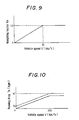
- first vehicle speed V S selected by low vehicle speed selection unit 101 is obtained by multiplying the smaller value V L of the two rear wheel speeds V RL and V RR , in multiplication unit 104, by a weighting factor K V corresponding to vehicle speed V calculated by equation (1).
- the reason why the smaller value V L , of the two rear wheel speeds V RL and V RR , is multiplied in multiplication unit 104 by weighting factor K V and added with the greater value V H of the two rear wheel speeds V RL and V RR, multiplied in multiplication unit 105 by (1 - K V ), to calculate vehicle speed V S is that, when, for example, operating on a small curvature road such as that which occurs when turning to the right or left at a crossroad, an average value of the peripheral speeds of front wheels 64 and 65 largely differs from the smaller value V L of the two rear wheel speeds V RL and V RR , and the driving torque correction by feedback tends to become too large, thereby deteriorating acceleration of vehicle 82.
- weighting factor K V is read from a graph shown in Fig.9 according to vehicle speed V of equation (1), which is an average value of the peripheral speeds of rear wheels 78 and 79, maintaining the acceleration performance of vehicle 82 even when operating on a curved road with a small curvature radius such as that which occurs when turning to the right or left at crossroads.
- present running acceleration G X(n) of vehicle 82 is calculated in differentiation unit 106 from presently calculated vehicle speed V S(n) and previously calculated vehicle speed V S(n-1) by the following equation: wherein ⁇ t is a sampling period of this control, that is, 15 milliseconds, for example, and g is a gravitational acceleration.
- longitudinal direction acceleration G X(n) is clipped by clipping unit 107 so that a maximum value of longitudinal direction acceleration G X(n) does not exceed 0.6g in view of safety reduction from miscalculation or the like. Furthermore, filtering occurs by filtration unit 108 to remove noise and allow calculation of corrected longitudinal direction acceleration G XF .
- This filtration is to correct longitudinal direction acceleration G X(n) so that slip rate S of the tires is maintained at target slip rate S O , or at a smaller value within its vicinity, corresponding to a maximum value of a friction coefficient between the tire and road surface. This occurs even when a maximum value of longitudinal direction acceleration G X(n) of vehicle 82 varies and slip rate S of the tires tends to come out of target slip rate S O , or of a smaller value within its vicinity, corresponding to the maximum value of a friction coefficient between the tire and road surface. This is because longitudinal direction acceleration G X(n) of vehicle 82 can be regarded as equivalent to the friction coefficient between the tire and road surface. This is performed as follows.
- present longitudinal direction acceleration G X(n) is greater than the filtered previously corrected longitudinal direction acceleration G XF(n-1) , that is, when vehicle 82 continues increasing speed, the present corrected longitudinal direction acceleration G XF(n) is delayed as to remove noise, causing corrected longitudinal direction acceleration G XF(n) to follow longitudinal direction acceleration G XF(n) relatively rapidly.
- Corrected longitudinal direction acceleration G XF with noise reduced by filtration unit 108 is torque converted by torque conversion unit 109.
- the filtration may alternatively be made after torque conversion by torque conversion unit 109.
- T B G FO ⁇ W b ⁇ r + T R + T C (4), wherein W b is a vehicle body weight, and r is an effective radius of front wheels 64 and 65.
- Running drag T R can be calculated as a function of vehicle speed V. However, in this embodiment, it is determined from a graph as shown in Fig.35. In this case, since running drag T R differs between a level road and an ascending slope, the graph contains a solid line curve for a level road and a two-dot-bar curve for an ascending road. One of these is selected according to a detection signal from an inclination sensor (not shown) incorporated in vehicle 82. However, running drag T R can also be set in detail by including a descending slope and the like.
- cornering drag correction torque T C is determined from a graph as shown in Fig.11, which can set reference driving torque T B of engine 11 approximate to the actual operating condition.
- Reference torque T B of engine 11, immediately after passing through a curve, is set slightly higher, thereby improving the feeling of acceleration of vehicle 82 after passing through a curved road.
- a lower limit value is set by variable clipping unit 115 to prevent reference driving torque T B , subtracted by final correction torque T PID (described later) by subtraction unit 116, from becoming a negative value.
- the lower limit value for reference driving torque T B is reduced, step by step over time, from the beginning of slip control, as shown in a graph in Fig.12.
- TCL 76 calculates actual front wheel speed V F according to a detection signal from front wheel rotation sensor 66. Further, as previously described, by feedback control of reference driving torque T OS using slip amount s, which is a difference between target front wheel speed V FO set according to front wheel speed V F and vehicle speed V S for slip control and target front wheel speed V FS for correction torque calculation, calculates target driving torque T OS of engine 11.
- slip rate S of the tires of front wheels 64 and 65, during operation to a smaller value, or a value within the vicinity of target slip rate S O corresponding to the friction coefficient between the tire and road surface. This prevents energy loss and prevents operability and acceleration performance from being deteriorated.
- target slip rate S O fluctuates in the range from 0.1 to 0.25 depending on the road condition
- TCL 76 reads slip correction amount V K corresponding to the previously described corrected longitudinal direction acceleration G XF from a graph as shown in Fig.38 by acceleration correction unit 118, and adds it to a reference torque calculation target front wheel speed V FO in addition unit 119.
- Slip correction amount V K has a tendency to increase, step by step, as corrected longitudinal direction acceleration G XF increases. Further, in this embodiment, this graph is prepared through running experimental tests or the like.
- correction torque calculation target front wheel speed V FS is increased, and slip rate S during acceleration is set to target slip rate S O shown by solid lines in Fig.13 or to a smaller value within its vicinity.
- slip correction value V KC corresponding to target lateral acceleration G YO is read from a graph as shown by solid lines in Fig.15 by turning correction unit 120, and the result is subtracted from reference torque calculation target front wheel speed V FO in subtraction unit 121.
- This is, provided, however, that before the first learning of neutral position ⁇ M of steering shaft 83 is made after ignition key switch 75 is turned on, turning angle ⁇ H of steering shaft 83 is not reliable.
- slip correction value V KC is read from a graph as shown by broken lines in Fig.15 according to lateral acceleration G Y actually applied to vehicle 82 by peripheral speeds V RL and V RR of rear wheels 78 and 79.
- Target lateral acceleration G YO is determined by calculating steering angle ⁇ by equation (2) according to a detection signal from steering angle sensor 84 and calculating from steering angle ⁇ by equation (3). Thereafter, neutral position ⁇ M is learning corrected.
- target lateral acceleration G YO may become an incorrect value. Then, when an abnormality occurs in steering angle sensor 84 or the like, actual lateral acceleration G Y generated in vehicle 82 is calculated by using the rear wheel speed difference
- actual lateral acceleration G Y is calculated from the rear wheel speed difference
- the present corrected lateral acceleration G YF(n) is low-pass filtered by the following digital calculation from the presently calculated lateral acceleration G Y(n) and the previously calculated corrected lateral acceleration G YF(n-1) .
- an abnormality occurs in steering angle sensor 84 or steering shaft reference position sensor 86, it can be detected by TCL 76, for example, using an open circuit detection circuit or the like as shown in Fig.16. Specifically, the output of steering angle sensor 84 and steering shaft reference position sensor 86 is pulled up by resistor R and grounded by capacitor C. Subsequently, the output is inputted to terminal AO of TCL 76 for use in various controls, and also to terminal A1 through comparator 88. The negative terminal of comparator 88 is applied with a reference voltage of 4.5V. When an open circuit occurs in steering angle sensor 84, input voltage to terminal AO exceeds the reference value. The comparator is then turned on, and the input voltage to terminal A1 is continuously at a high level H.
- the program of TCL 76 is set so that when the input voltage to terminal A1 is at a high level H for a predetermined period of time, for example, 2 seconds, it is determined as an open circuit. This thereby detects an occurrence of an abnormality of steering angle sensor 84 or steering shaft reference position sensor 86.
- an abnormality of steering angle sensor 84 or the like is detected by hardware.
- an abnormality can naturally be detected by software
- TCL 76 first detects an abnormality by an open circuit as shown in Fig.16 in step W1. When it is determined not to be an abnormality, it is then determined in step W2 whether or not there is an abnormality in front wheel rotation sensor 66 and rear wheel rotation sensors 80 and 81. When, in step W2, rotation sensors 66, 80, and 81 are determined not to have an abnormality, a determination is made in step W3 as to whether or not steering shaft 83 has rotated more than one turn, for example, more than 400 degrees, in the same direction.
- step W4 When it is determined in step W3 that steering shaft 83 has been steered or turned more than 400 degrees in the same direction, a determination is made in step W4 as to whether or not there is a signal to notice reference position ⁇ N of steering shaft 83 from steering shaft reference position sensor 86.
- step W4 it is determined that there is no signal to notice reference position ⁇ N of steering shaft 83, since there should be at least one signal to notice reference position ⁇ N of steering shaft 83 if steering shaft reference position sensor 86 is normal, steering angle sensor 84 is determined as being abnormal in step W4, and an abnormality occurrence flag F W is set.
- step W3 it is determined that steering shaft 83 has not been steered more than 400 degrees in the same direction, or when, in step W4, it is determined that there is a signal to notice reference position ⁇ N of steering shaft 83 from steering shaft reference position sensor 86, a determination is made in step W6 as to whether or not neutral position ⁇ M has been learned. That is, it is determined whether or not at least one of the two steering angle neutral position learned flags, F HN or F H , is set.
- step W6 it is determined that learning of neutral position ⁇ M of steering shaft 83 has finished, and when it is determined in step W7 that rear wheel speed difference
- Slip correction amount V KC corresponding to target lateral acceleration G YO is set to a value smaller than slip correction amount V KC corresponding to corrected lateral acceleration G YF in the range of small target lateral acceleration G YO in view of an additional turning of steering wheel 85 by the driver. Since it is preferable to ensure acceleration of vehicle 82 in the range of small vehicle speed V, and, to the contrary, it is necessary to consider ease of turning at a vehicle speed V of more than a certain value, the slip correction amount V KC read from Fig.39 is multiplied by a correction factor corresponding to vehicle speed V read from the graph of Fig.42, to calculate a corrected slip correction amount V KF .
- TCL 76 adopts, in step T1, corrected lateral acceleration G YF from filtration unit 123 as the lateral acceleration to calculate slip correction amount V KC . A determination is then made in step T2 as to whether or not slip control flag F S is set.
- step T2 When, in step T2, it is determined that slip control flag F S is set, corrected lateral acceleration G YF is adopted. This is because, when lateral acceleration to determine slip correction amount V KC is changed from corrected lateral acceleration G YF to target lateral acceleration G YO , slip correction amount V KC tends to be largely changed and the behavior of vehicle 82 tends to become disturbed.
- step T3 When, in step T2, it is determined that slip control flag F S is not set, a determination is made in step T3 as to whether or not any one of two steering angle neutral position learned flags F HN and F H is set. In this case, when both steering angle neutral position learned flags F HN and F H are determined as not being set, corrected lateral acceleration G YF is adopted, as is. When it is determined in step T3 that one of steering angle neutral position learned flags F HN and F H is set, target lateral acceleration G YO is adopted as the lateral acceleration to calculate slip correction amount V KC in step T4.
- slip amount s which is the difference between actual front wheel speed V F obtained from filtration to remove noise from the detection signal from front wheel rotation sensor 66, and correction torque calculation target front wheel speed V FS , is calculated by reduction unit 124.
- slip amount s is less than the negative setting value, for example, -2.5 km per hour
- the -2.5 km per hour is clipped as the slip amount s in clipping unit 125.
- the clipped slip amount s is subjected to proportional correction to be described later. This prevents overcontrol in proportional correction and further prevents the occurrence of hunting in the output.
- slip amount s before clipping is integration corrected using ⁇ T I , to be described later. It is then differentiation corrected to calculate final correction torque T PID .
- proportional correction slip amount s is multiplied by proportional coefficient K P in multiplication unit 126 to obtain a basic correction amount. It is then multiplied in multiplication unit 127 by correction factor ⁇ KP , previously set from speed change ratio ⁇ m of hydraulic automatic transmission 13, to obtain proportional correction torque T P .
- Proportional coefficient K P is read from a graph shown in Fig.20 according to the clipped slip amount s.
- a basic correction amount is calculated by integration calculation unit 128.
- the correction amount is the multiplied by correction factor ⁇ KI predetermined according to speed change ratio ⁇ m of hydraulic automatic transmission 13 in multiplication unit 129, to obtain integration correction torque T I .
- a constant small integration correction torque ⁇ T I is integrated, and a small integration correction torque ⁇ T I is added when the slip amount s is positive, every 15-millisecond sampling period, or, a small integration correction torque ⁇ T I is subtracted when the slip amount s is negative.
- torque T I is set to a lower limit value T I as shown in a graph in Fig.21, which is variable according to vehicle speed V.
- T I a large integration correction torque T I is applied at the starting of vehicle 82, especially at the start of an ascending slope, to ensure the driving torque of engine 11.
- an upper limit value for example, 0 kgm, is set to enhance the convergence of control, and integration torque T I varies as shown in Fig.22 by this clipping.
- proportional correction torque T P is added to integration correction torque T I in addition unit 130 to calculate proportional integration correction torque T PI .
- Correction factors ⁇ KP and ⁇ KI are read from a graph as shown in Fig.23, which is previously set in relation to speed change ratio ⁇ m of hydraulic automatic transmission 13.
- changing rate G S of the slip amount s is calculated in differentiation calculation unit 131, and multiplied by differentiation coefficient K D in multiplication unit 132, to calculate a basic correction amount for rapid changes in the slip amount s. Further, an upper limit value and a lower limit value are individually set for the above obtained value, and a differentiation correction torque T D is clipped in clipping unit 133 to prevent it from becoming an extremely large value, to obtain differentiation correction torque T D . Since, during the running of vehicle 82, wheel speeds V F , V RL , and V RR may become instantaneously skidded or locked, depending on the road condition or the running condition of vehicle 82, changing rate G S of the slip amount s may become an extremely larger positive or negative value.
- the lower limit value is clipped, for example, to -55 kgm and the upper limit value is clipped to 55 kgm, to prevent the differentiation correction torque T D from becoming to extremely large in value.
- proportional integration correction torque T PI is added to differentiation correction torque T D in addition unit 134.
- the resulting final correction torque T PID is subtracted in subtraction unit 116 from reference driving torque T B , and further multiplied in multiplication unit 135 by a reciprocal of the total reduction ratio between engine 11 and wheel shafts 89 and 90 of front wheels 64 and 65, to obtain target driving torque T os for slip control, as shown in equation (6) below:
- ⁇ d is a differential gear reduction ratio
- ⁇ T is a torque converter ratio.
- target driving torque T OS calculated by equation (6) should naturally be a positive value
- target driving torque T OS is clipped to a value above zero in clipping unit 136, in order to prevent miscalculation.
- Information on target driving torque T OS is outputted to ECU 15 according to determination processing in start/end determination unit 137, to determine the start or end of slip control.
- Start/end determination unit 137 determines the start of slip control when all conditions of (a) through (e) below are met; sets slip control flag F S ; operates select switch 103 to select the output from low vehicle speed selection unit 101 as the slip control vehicle speed V S ; outputs information on target driving torque T OS to ECU 15; determines the end of slip control; and repeats the procedures until the end of slip control is determined and slip control flag F S is reset.
- start/end determination unit 137 determines start of slip control, it is determined as the completion of slip control, slip control flag F s is reset, transmission of target driving torque T OS to ECU 15 is discontinued, and select switch 103 is operated to select the output from high vehicle speed selection unit 102 as the vehicle speed V S for slip control.
- Vehicle 82 is provided with a manual switch (not shown) for the driver to select slip control.
- a manual switch (not shown) for the driver to select slip control.
- TCL 75 in step S1 calculates target driving torque T OS by the detection of the above-described various data and calculation. However, this calculation operation is performed independently from operation of the manual switch.
- step S2 a determination is made as to whether or not slip control flag F S is set.
- TCL 76 determines in step S3 whether or not the slip amount s of the front wheels 64 and 65 is greater than a predetermined threshold value, for example, 2 km per hour.
- TCL 76 determines in step S4 whether or not changing rate G S of the slip amount s is greater than 0.2 g.
- TCL 76 determines in step S5 whether or not the driver's required driving torque T d is greater than a minimum driving torque necessary to run vehicle 82, for example, greater than 4 kgm. That is, it determines whether or not the driver intends to run vehicle 82.
- step S5 When, in step S5, it is determined that the required driving torque T d is greater than 4 kgm, that is, the driver intends to run vehicle 82, slip control flag F S is set in step S6. Further, a determination is again made in step S7 as to whether or not slip control flag F s is set.
- step S7 When, in step S7, it is determined that slip control flag F S is set, slip control target driving torque T OS , previously calculated by equation (6), is adopted in step S8 as target driving torque T OS for engine 11.
- step S7 When, in step S7, it is determined that slip control flag F S is reset, TCL 76 in step S9 outputs a maximum torque of engine 11 as target driving torque T OS , thereby reducing the duty ratio of torque control electromagnetic valves 51 and 56 to the 0% side. As a result, engine 11 outputs a driving torque according to the amount of pressure applied to the accelerator pedal 31 by the driver.
- step S3 it is determined that the slip amount s of front wheels 64 and 65 is smaller than 2 km per hour; or, in step S4, it is determined that slip amount changing rate G s is smaller than 0.2 g; or, in step S5, it is determined that required driving torque T d is smaller than 4 kgm
- step S9 TCL 76 outputs the maximum torque of engine 11 as target driving torque T OS , and ECU 15 reduces the duty ratio of torque control electromagnetic valves 51 and 56 to the 0% side.
- engine 11 generates a driving torque according to the amount of pressure applied to the accelerator pedal 31 by the driver.
- step S10 determines whether or not the condition that the slip amount s of front wheels 64 and 65 is below -2 km, which is the above-described threshold value, and as to whether the required driving torque T d is below target driving torque T OS , calculated in step S1, and has continued for 0.5 seconds or more.
- step S10 it is determined that the condition that the slip amount s is smaller than 2 km per hour and the required driving torque T d is below target driving torque T OS and has continued for 0.5 seconds or more, that is, the driver no longer requires acceleration of vehicle 82, in step S11, slip control flag F S is reset, and processing proceeds to step S7.
- step S10 determines whether or not the condition that the slip amount s is greater than 2 km per hour, or the condition that the required driving torque T d is below target driving torque T OS , and has not continued for 0.5 seconds or more, that is, the driver requires acceleration of vehicle 82.
- TCL 76 in step S12 determines whether or not the condition that idle switch 68 is on, that is, throttle valve 20 is fully closed, has continued for 0.5 seconds or more.
- step S12 it is determined that idle switch 68 is on, since the driver is not pressing down on accelerator pedal 31, processing proceeds to step S11 where slip control flag F S is reset. To the contrary, when it is determined that idle switch 68 is off, since the driver is pressing down on accelerator pedal 31, processing again proceeds to step S7.
- TCL 76 calculates slip control target driving torque T OS , and then calculates the target driving torque of engine 11 for turning control.
- Lateral acceleration G Y of vehicle 82 can be actually calculated by equation (5) using rear wheel speed difference
- TCL 76 calculates target lateral acceleration G YO of vehicle 82 by equation (3) from steering shaft turning angle ⁇ H and vehicle speed V, and an acceleration in the longitudinal direction of vehicle 82 of non-extreme under-steering. That is, the target longitudinal direction acceleration G XO is set according to the target lateral acceleration G YO . Further, target driving torque T OC of engine 11 corresponding to this target longitudinal direction acceleration G XO is calculated.
- TCL 76 calculates vehicle speed V in vehicle speed calculation unit 140 by equation (1) from the output of a pair of rear wheel rotation sensors 80 and 81. It further calculates the steering angle ⁇ of front wheels 64 and 65 by equation (2) according to a detection signal from steering angle sensor 84. Also, in target. lateral acceleration calculation unit 141, target lateral acceleration G YO of vehicle 82, at this time, is also calculated by equation (3).
- target lateral acceleration G YO is multiplied by correction factor K Y as shown in Fig.27, according to vehicle speed V.
- corrected lateral acceleration G YF is selected by select switch 143. Further, when at least one of steering angle neutral position learned flags F HN and F H is set, target lateral acceleration G YO from correction factor multiplication unit 142 is selected by select switch 143.
- the stability factor A is determined by the suspension arrangement of vehicle 82 or characteristics of tires or road surface condition. Specifically, it is represented as the gradient of a tangential line in the graph, for example, as shown in Fig.28.
- Fig.28 shows the relationship between actual lateral acceleration G Y generated in vehicle 82 during steady circular turning and steering angle ratio ⁇ H / ⁇ HO of steering shaft 83 at that time (the ratio of turning angle ⁇ H of steering shaft 83 at an acceleration to turning angle ⁇ HO of steering shaft 83 under extremely low-speed running condition where lateral acceleration G Y is in the vicinity of zero with respect to neutral position ⁇ M of steering shaft 83).
- stability factor A is set to 0.002
- the driving torque of engine 11 is controlled so that target lateral acceleration G YO of vehicle 82 calculated by equation (3) is less than 0.6g.
- stability factor A may be set, for example, to about 0.005.
- target lateral acceleration G YO is greater than actual lateral acceleration G Y on a low ⁇ road
- a determination is made as to whether or not target lateral acceleration G YO is greater than a predetermined threshold value, for example, (G YF - 2).
- target lateral acceleration G YO is greater than the threshold value, vehicle 82 is determined as running on a low ⁇ road.
- low ⁇ road turning control may be performed as needed.
- vehicle 82 is determined as running on a low ⁇ road.
- target longitudinal direction acceleration G XO of vehicle 82 is read by target longitudinal direction acceleration calculation unit 144 from a graph as shown Fig.29, which has been previously stored in TCL 76.
- Reference driving torque T B of engine 11 according to target longitudinal direction acceleration G XO is calculated in reference driving torque calculation unit 145 by equation (7).
- T L is a road-load torque which is a resistance of road surface determined as a function of lateral acceleration G Y of vehicle 82, and, in this embodiment, is determined from a graph as shown in Fig.30.
- reference driving torque T B is multiplied, in multiplication unit 146, by a weighting factor ⁇ to determine a corrected reference driving torque.
- This weighting factor ⁇ is experimentally set by turning running vehicle 82. A value of approximately 0.6 is used for a high ⁇ road.
- target driving torque T OC of engine 11 is calculated by equation (8) in addition unit 148.
- T OC ⁇ ⁇ T B + (1- ⁇ ) ⁇ T d (8)
- Start/end determination unit 150 determines the beginning of turning control when all conditions of (a) through (d) below are met, turning control flag F C being set, outputs information on target driving torque T OC to ECU 15, and continues this procedure until the completion of turning control is determined and turning control flag F C is reset.
- start/end determination unit 150 determines the beginning of turning control, and when any one of the conditions (e) and (f) below is met, it is determined as the completion of turning control, turning control flag F C is reset, and transmission of target driving torque T OC to ECU 15 is discontinued.
- accelerator opening sensor 77 is mounted to throttle body 21 so that the output voltage of accelerator opening sensor 77 is, for example, 0.6 volts when accelerator opening ⁇ A is fully closed.
- the full-close position of accelerator opening sensor 77 is learning corrected, thereby ensuring reliability of accelerator opening ⁇ A calculated according to a detection signal from accelerator opening sensor 77.
- Fig.31 showing the full-close position learning procedure of accelerator opening sensor 77
- output of accelerator opening sensor 77 is monitored for a predetermined period of time, for example, for 2 seconds.
- a lowest value of accelerator opening sensor 77 output is taken in as a full-close position of accelerator opening sensor 77. This is stored in a RAM with backup (not shown) incorporated in ECU 15.
- accelerator opening ⁇ A is corrected with respect to the lowest output of accelerator opening sensor 77 until the next learning.
- TCL 76 determines in step A1 whether or not full-close position value ⁇ AC of accelerator opening ⁇ A is stored in the RAM. Further, when it is determined in step A1 that full-close position value ⁇ AC of accelerator opening ⁇ A is not stored in the RAM, initial value ⁇ A(O) is stored in the RAM in step A2.
- step A1 when it is determined in step A1 that full-close position value ⁇ AC of accelerator opening ⁇ A is stored in the RAM, a determination is made in step A3 as to whether or not ignition key switch 75 is on.
- step A3 When it is determined that ignition key switch 75 is changed from on to off, the counting of a learning timer (not shown) is started in step A4. After the counting of the learning timer is started, a determination is made in step A5 as to whether or not idle switch 68 is on.
- step A5 When it is determined in step A5 that idle switch 68 is off, a determination is made in step A6 that the count of the learning timer has reached a predetermined value, for example, 2 seconds. Processing reverts back to step A5.
- step A5 When it is determined in step A5 that idle switch 68 is on, output of accelerator opening sensor 77 is read in step A7 at a predetermined period, and a determination is made in step A8 whether or not present accelerator opening ⁇ A(n) is smaller than minimum value ⁇ AL of previous accelerator opening ⁇ A .
- step A9 When it is determined that present accelerator opening ⁇ A(n) is greater than minimum value ⁇ AL of previous accelerator opening ⁇ A , minimum value ⁇ AL of previous accelerator opening ⁇ A is maintained as is. On the contrary, however, when it is determined that present accelerator opening ⁇ A(n) is smaller than minimum value ⁇ AL of previous accelerator opening ⁇ A , present accelerator opening ⁇ A(n) is adopted in step A9 as the new minimum value ⁇ AL . This procedure is repeated until the count of the learning timer reaches the predetermined value, for example, 2 seconds, in step A6.
- step A10 When count of the learning timer reaches the predetermined value, a determination is made in step A10 as to whether or not minimum value ⁇ AL of accelerator opening ⁇ A is between predetermined clipping values, for example, between 0.3 V and 0.9 V. When it is determined that minimum value ⁇ AL of accelerator opening ⁇ A is within the clipping range, initial value ⁇ A(o) or full-close position value ⁇ AC of accelerator opening ⁇ A is brought closer in the direction of minimum value ⁇ AL by a constant value, for example, by 0.1 V. Subsequently, the result is adopted in step A11 as the full-close position value ⁇ AC(n) of accelerator opening ⁇ A of the present learning.
- step A12 When it is determined in step A10 that minimum value ⁇ AL of accelerator opening ⁇ A is out of the predetermined clipping range, in step A12, the clipping value which is out of the range is replaced as minimum value ⁇ AL of accelerator opening ⁇ A . Processing then proceeds to step A11 where full-close position value ⁇ AC of accelerator opening ⁇ A is learning corrected.
- the timing for starting the learning of full-close position value ⁇ AC of accelerator opening ⁇ A is set with respect to the time at which ignition key switch 75 is changed from on to off.
- a seat sensor incorporated in a seat may be used, wherein the driver leaving the seat is detected using changes in seat pressure or is position detected by the seat sensor, even when ignition key switch 75 is on, to begin learning of step A4 and beyond.
- a door-lock system (not shown), externally manipulated, is detected, or, a key entry system is used to detect that the door-lock system is manipulated, to begin learning of full-close position value ⁇ AC of accelerator opening sensor 77.
- learning may be performed when a shift lever (not shown) of the hydraulic automatic transmission 13 is positioned at the neutral or parking position (neutral position for a vehicle with a manual transmission), and an air-conditioning system is off, that is, when the vehicle is not in an idle up state.
- Vehicle 82 is provided with a manual switch (not shown) for the driver to select turning control. When the driver selects this switch for turning control, the following turning control operation is performed.
- target driving torque T OC is calculated in step C1 by detection and calculation of various data, independent of operation of the manual switch.
- step C2 a determination is made in step C2 as to whether or not vehicle 82 is under turning control, that is, whether or not turning control flag F C is set. Since initially, vehicle 82 is not under turning control, and turning control flag F C is determined as being in the reset state, a determination is made in step C3 as to whether or not it is smaller than (T d - 2). That is, target driving torque T OC can be calculated even when vehicle 82 is running straightforward, but the value is normally greater than the required driving torque T d of the driver. However, since the required driving torque T d is generally small during the turning of vehicle 82, the time when target driving torque T OC becomes a value below the threshold value (T d - 2) is determined as the starting condition for turning control.
- This threshold value is set to (T d - 2) as a hysteresis to prevent the hunting of control.
- TCL 76 determines in step C4 whether or not idle switch 68 is off.
- step C4 When it is determined in step C4 that idle switch 68 is off, that is, accelerator pedal 31 is pressed down by the driver, turning control flag F C is set in step C5. Then, a determination is made in step C6 as to whether or not at least one of two steering angle neutral position learned flags F HN and F H is set, that is, authenticity of steering angle ⁇ detected by steering angle sensor 84 is determined.
- step C6 When it is determined in step C6 that at least one of two steering angle neutral position learned flags F HN and F H is set, a determination is made again in step C7 as to whether or not turning control flag F C is set.
- step C5 since turning control flag F C is set in step C5, it is determined that in step C7 that turning control flag F C is set.
- the previously calculated target driving torque T OC in step C1, is adopted, as is, in step C8, as target driving torque T OH .
- step C6 determines whether or not turning control flag F C is set.
- step C17 determines whether or not turning control flag F C is set.
- processing proceeds to step C8.
- target driving torque T OC of equation (8) according to corrected lateral acceleration of equation (5) is adopted as turning control target driving torque T OC , since the steering angle ⁇ calculated by equation (2) is enormous.
- step C17 When it is determined in step C17 that turning control flag F C is not set, target driving torque T OC calculated by equation (8) is not adopted.
- TCL 76 outputs in step C9 a maximum torque of engine 11 as target driving torque T OC , which causes ECU 15 to reduce the duty ratio of torque control electromagnetic valves 51 and 56 to the 0% side, and engine 11 generates driving torque according to the amount of pressure applied to the accelerator pedal 31 by the driver.
- step C3 When it is determined in step C3 that target driving torque T OC is not smaller than threshold value (T d - 2), processing does not go to turning control, but instead goes to step C6 or steps C7 to C9, where TCL 76 outputs a maximum torque of engine 11 as target driving torque T OC .
- TCL 76 outputs a maximum driving torque of engine 11 as target driving torque T OC .
- step C10 When, in step C2, it is determined that turning control flag F C is set, a determination is made in step C10 as to whether or not the difference ⁇ T between the presently calculated target driving torque T OC and the previously calculated target driving torque T OC(n-1) is greater than a predetermined change allowance T K .
- This change allowance T K is a torque change such that the passenger feels no speed change shock, for example.
- step C10 When, in step C10, it is determined that the difference ⁇ T between the presently calculated target driving torque T OC and the previously calculated target driving torque T OC(n-1) is not greater than a predetermined change allowance T K , a determination is made in step C11 as to whether or not the difference ⁇ T between the presently calculated target driving torque T OC and the previously calculated target driving torque T OC(n-1) is greater than the negative change allowance T K .
- step C11 it is determined that the difference ⁇ T between the presently calculated target driving torque T OC and the previously calculated target driving torque T OC(n-1) is greater than the negative change allowance T K, since the absolute value of the difference
- step C11 When, in step C11, it is determined that a difference ⁇ T between the presently calculated target driving torque T OC and the previously calculated target driving torque T OC(n-1) is not greater than a negative change allowance T K , the present target driving torque T OC is corrected in step C12 by the following equation, and adopted as the calculated value in step C8.
- T OC T OC(n-1) - T K
- step C10 when, in step C10, it is determined that a difference ⁇ T between the presently calculated target driving torque T OC and the previously calculated target driving torque T OC(n-1) is greater than a change allowance T K , the present target driving torque T OC(n) is corrected in step C13 by the following equation, and adopted as calculated value in step C8.
- T OC T OC(n-1) + T K
- TCL 76 determines whether or not this target driving torque T OH is greater than required driving torque T d of the driver.
- step C15 Since target driving torque T OC is not greater than driving torque T d required by the driver when turning control flag F C is set, a determination is made in step C15 as to whether or not idle switch 68 is on.
- step C15 When, in step C15, it is determined that idle switch 68 is on, processing goes to step C6 because turning control is required.
- step C7 it is determined that turning control flag F C is set, or, in step C17, it is determined that turning control flag F C is set, the calculated value adopted in step C1 or step C12 or step C13 is selected as turning control target driving torque T OC .
- step C14 When, in step C14, it is determined that target driving torque T OC is greater than required driving torque T d of the driver, which means completion of turning of vehicle 82, in step C16, TCL 76 resets turning control flag F C .
- step C15 when it is determined in step C15 that idle switch 68 is on, that is, the accelerator pedal is not pressed down, processing proceeds to step C16 where turning control flag F C is reset.
- TCL 76 When, in step C16, turning control flag F C is reset, TCL 76 outputs a maximum driving torque of engine 11 as target driving torque T OC . This causes ECU 15 to reduce the duty ratio of torque control electromagnetic valves 51 and 56 to the 0% side, and engine 11 generates driving torque according to the amount of pressure applied to the accelerator pedal 31 by the driver.
- reference driving torque T B which can be calculated by equation (7), may be adopted as a target driving torque.
- the factor ⁇ may be gradually decreased with time after the beginning of control, or the factor ⁇ may be gradually decreased with vehicle speed, and the ratio of required driving torque T d may be gradually increased.
- the factor ⁇ may remain constant for a period of time after the beginning of control, and then can be decreased.
- the factor ⁇ may be increased with increasing steering shaft turning amount ⁇ H , especially to run vehicle 82 safely along a turning road of which the curvature radius gradually decreases.
- the high ⁇ road target driving torque is calculated.
- turning control target driving torques T OH and T OL for high ⁇ road and low ⁇ road may be individually calculated, and a final target driving torque be selected from these target driving torques.
- regulation is applied to target driving torque T OC by change allowance T K , in order to prevent speed change shocks due to rapid changes in driving torque of engine 11.
- this regulation may alternatively be applied to target longitudinal direction acceleration G XO .
- TCL 76 selects optimum final target driving torque T O from among these two target driving torques T OS and T OC , and outputs this to ECU 15. In this case, the smaller target driving torque is preferentially outputted, in view of running safety of vehicle 82.
- final target driving torque T O may be selected in the order of slip control and turning control.
- step M11 As shown in Fig.34 which shows this processing flow, after slip control target driving torque T OS and turning control target driving torque T OC are calculated in step M11, a determination is made in step M12 as to whether or not slip control flag F S is set. When it is determined that slip control flag F S is set, slip control target driving torque T OS is selected in step M13 as the final target driving torque T O , and outputted to ECU 15.
- step M12 When, in step M12, it is determined that slip control flag F S is not set, a determination is made in step M14 as to whether or not turning control flag F C is set. When it is determined that turning control flag F C is set, turning control target driving torque T OC is selected in step M15 as final target driving torque T O , and outputted to ECU 15.
- TCL 76 in step M16 outputs a maximum torque of engine 11 as the final target driving torque T O to ECU 15.
- TCL 76 sets in a retard angle ratio to the basic retard angle value p S of ignition timing P set by ECU 15, which is outputted to ECU 15.
- Basic retard angle value p S is a maximum value of the retard angle that presents no problem relating to operation of engine 11. It is set according to the intake air amount and engine speed N E of engine 11. As the retard angle ratio, four levels are set in this embodiment: level O in which basic retard angle value is 0; level I in which basic retard angle value p S is compressed to two-thirds; level II in which basic retard angle value p S is outputted as is; and level III which basic retard angle value p S is outputted as is and throttle valve 20 is fully closed. Graphs of the retard angle ratio, in which the basic retard angle value increases as the changing rate of slip amount s increases, are stored in TCL 76.
- step P2 a determination is made in step P2 as to whether or not slip control flag F S is set.
- step P4 a determination is made in step P4 as to whether or not the slip amount s is smaller than 0 km per hour.
- step P4 When it is determined in step P4 that the slip amount s is smaller than 0 km per hour, that is, increasing driving torque of engine 11 presents no problem, the retard angle ratio is set to level O in step P5, which is outputted to ECU 15.
- step P6 a determination is made in step P6 as to whether or not slip amount changing rate G S is smaller than 2.5 g.
- step P7 a determination is made in step P7 as to whether or not retard angle ratio is at level III.
- step P6 When it is determined in step P6 that slip amount changing rate G S exceeds 2.5 g, that is, front wheels 64 and 65 considerably slip, a determination is made in step P8 as to whether or not the final target driving torque T o is smaller than 4 kgm.
- the retard angle ratio is set in step P9 to level III, and processing proceeds to step P7.
- step P8 When it is determined in step P8 that the final target driving torque T O is greater than 4 kgm, nothing is done and processing proceeds to step P7.
- step P10 When it is determined in step P7 that the retard angle ratio is that of level III, a determination is made in step P10 as to whether or not slip amount changing rate G S exceeds 0 g. When it is determined that slip amount changing rate G S exceeds 0 g, that is, the slip amount s tends to increase, a determination is made in step P11 as to whether or not ignition timing control flag F P is set. When it is determined in step P10 that slip amount changing rate G S is smaller than 0 g, that is, the slip amount s tends to decrease, a determination is made in step P12 as to whether or not the slip amount s exceeds 8 km per hour.
- step P12 When it is determined in step P12 that the slip amount s exceeds 8 km per hour, processing proceeds to step P11. When it is determined that the slip amount s is smaller than 8 km per hour, the retard angle ratio is switched from level III to level II in step P13. Subsequently, a determination is made in step P14 as to whether or not slip amount changing rate G S is smaller than 0.5 g. Similarly, when it is determined in step P7 that the retard angle ratio is not at level III, processing also goes to step P14.
- step P14 When it is determined in step P14 that slip amount changing rate G S is smaller than 0.5 g, that is, the change in the slip amount s is not very rapid, a determination is made in step P15 as to whether or not the retard angle ratio is at level II. When it is determined in step P14 that slip amount changing rate G S is not smaller than 0.5 g, the retard angle ratio is set in step P16 to level II, and processing proceeds to step P15.
- step P15 When it is determined in step P15 that the retard angle ratio is at level II, a determination is made in step P16 as to whether or not slip amount changing rate G S exceeds 0 g. On the contrary, when it is determined that the retard angle ratio is not at level II, a determination is made in step P17 as to whether or not slip amount changing rate G S is smaller than 0.3 g. When it is determined in step P16 that slip amount changing rate G S does not exceed 0 g, that is, the slip amount s tends to decrease, a determination is made in step P18 as to whether or not the slip amount s exceeds 8 km per hour.
- step P18 When it is determined in step P18 that the slip amount s is smaller than 8 km per hour, the retard angle ratio is switched in step P19 from level II to level I. Subsequently, processing proceeds to step P17.
- step P16 slip amount changing rate G S is greater than 0 g, that is, the slip amount s tends to increase, and when it is determined that the slip amount s is large, in the individual cases, processing proceeds to step P11.
- step P17 When it is determined in step P17 that slip amount changing rate G S is smaller than 0.3 g, that is, the slip amount s almost does not tend to increase, a determination is made in step P20 as to whether or not the retard angle ratio is at level I. To the contrary, when it is determined in step P17 that slip amount changing rate G S exceeds 0.3 g, that is, the slip amount s tends to increase to some extent, the retard angle ratio is set to level I in step P21.
- step P20 When it is determined in step P20 that the retard angle ratio is at level I, a determination is made in step P22 as to whether or not slip amount changing rate G S exceeds 0 g. Further, when it is determined to be less than 0 g, that is, the slip amount s tends to decrease, a determination is made in step P23 as to whether or not the slip amount s is smaller than 5 km per hour. When it is determined in step P23 that the slip amount s is smaller than 5 km per hour, that is, front wheels 64 and 65 are almost not slipping, the retard angle ratio is set to level 0 in step P24, which is outputted to ECU 15.
- step P20 When it is determined in step P20 that the retard angle ratio is not at level I; or, when it is determined in step P22 that slip amount changing rate G S exceeds 0 g, that is, the slip amount s tends to increase; or, when it is determined in step P23 that the slip amount s is greater than 5 km per hour, that is, the slip amount s is relatively large, the processing proceeds to step P11.
- step P11 when it is determined in step P11 that ignition timing control flag F P is set, a determination is made in step P25 as to whether or not the final target driving torque T O is smaller than 10 kgm.
- step P11 when it is determined in step P11 that ignition timing control flag F P is not set, the retard angle ratio is set to level O in step P26 and processing goes to step P25.
- step P25 When it is determined in step P25 that the final target driving torque T O is greater than 10 kgm, that is engine 11 generates a relatively high driving torque, a determination is made in step P27 as to whether or not the retard angle ratio is at level II. Further, when the retard angle ratio is determined to be at level II, the retard angle ratio is decreased to level I in step P28, which is outputted to ECU 15.
- step P25 When it is determined in step P25 that the final target driving torque T O is smaller than 10 kgm, or, when it is determined in step P27 that the retard angle ratio is not at level II, a determination is made in step P29 as to whether or not hydraulic automatic transmission 13 is speed changing. When it is determined that hydraulic automatic transmission 13 is speed changing, a determination is made in step P30 as to whether or not the retard angle ratio is at level III. When it is determined in step P30 that the retard angle ratio is at level III, the retard angle ratio is decreased to level II in step P31, which is outputted to ECU 15. When it is determined in step P29 that hydraulic automatic transmission 13 is not speed changing, or, when it is determined in step P30 that the retard angle ratio is not at level III, the set retard angle ratio is outputted, as is, to ECU 15.
- step P9 when retard angle ratio of level III is set in step P9, when it is determined that slip amount changing rate G S exceeds 0 g and the slip amount s exceeds 8 km per hour, that is, the increasing rate of the slip amount s is rapid, and the final target driving torque T O is smaller than 10 kgm, and it is difficult to efficiently suppress slipping of front wheels 64 and 65 only by the retard angle operation of ignition timing, the retard angle ratio of level III is selected and opening of throttle valve 20 is forcibly fully closed. This thereby efficiently suppresses the occurrence of slip at its initial stage.
- ECU 15 reads ignition timing P and basic retard angle p S according to a detection signal from crank angle sensor 62 and a detection signal from air flow sensor 70 from a graph (not shown) on ignition timing P and basic retard angle p S preset according to engine speed N E and intake air amount of engine 11, which are corrected according to a retard angle ratio transmitted from TCL 76 to calculate target retard angle p O .
- an upper limit value of target retard angle p O is set according to an upper limit temperature not damaging to exhaust gas cleaning catalyst (not shown), and the exhaust gas temperature is detected from a detection signal from exhaust gas temperature sensor 74.
- ECU 15 first determines in step Q1 whether or not slip control flag F S is set. When it is determined that slip control flag F S is set, a determination is made in step Q2 as to whether or not the retard angle ratio is set to level III.
- step Q2 When it is determined in step Q2 that the retard angle ratio is at level III, basic retard angle p S read from the graph is used, as is, as target retard angle p O , and ignition timing P is retarded by target retard angle p O . Furthermore, the duty ratio of torque control electromagnetic valves 51 and 56 is set to 100% so that throttle valve 20 is fully closed independent of the final target driving torque T O , thereby forcibly achieving full-close state of throttle valve 20.
- step Q5 When it is determined in step Q2 that the retard angle ratio is not at level III, a determination is made in step Q5 as to whether or not the retard angle ratio is set to level II.
- retard angle p O read from the graph is used, as is, in step Q6, as target retard angle p O , as in step Q3, and ignition timing P is retarded by target retard angle p O .
- ECU 15 sets in step Q7 the duty ratio of torque control electromagnetic valves 51 and 56 according to target driving torque T OS , to thereby reduce the driving torque of engine 11 independent of the amount of pressure applied to the accelerator pedal 31 by the driver.
- ECU 15 stores graphs to determine throttle opening ⁇ T from engine speed N E and driving torque of engine 11 as parameters, and ECU 15 reads target throttle opening ⁇ TO according to present engine speed N E and target driving torque T OS from the graphs.
- ECU 15 determines deviation between target throttle opening ⁇ TO and actual throttle opening ⁇ T outputted from throttle opening sensor 67, sets the duty ratio of the pair of torque control electromagnetic valves 51 and 56 to a value, according to the deviation, to supply current to solenoids of plungers 52 and 57 of individual torque control electromagnetic valves 51 and 56. It further controls actual throttle opening ⁇ T to decrease to target throttle opening ⁇ TO by the operation of actuator 41.
- ECU 15 When a maximum driving torque of engine 11 is outputted as target driving torque T OS to ECU 15, ECU 15 reduces the duty ratio of torque control electromagnetic valves 51 and 56 to the 0% side. This causes engine 11 to generate a driving torque according to the amount of pressure applied to the accelerator pedal 31 by the driver.
- step Q8 a determination is made in step Q8 as to whether or not the retard angle ratio is set to level I.
- target retard angle p O is set to the following equation to retard ignition timing P by target retard angle p O , and processing proceeds to step Q7.
- p O p S ⁇ 2 3
- step Q8 when it is determined in step Q8 that the retard angle ratio is not at level I, a determination is made in step Q10 as to whether or not retard angle p O is O. When it is determined as O, processing proceeds to step Q7 where ignition timing P is not retarded.
- the duty ratio of torque control electromagnetic valves 51 and 56 is thereby set according to target driving torque T O to reduce the driving torque of engine 11 independent of the amount of pressure applied to the accelerator pedal 31 by the driver.
- the duty ratio of torque control electromagnetic valves 51 and 56 is set to 0% in step Q13 to cause engine 11 to generate a driving torque according to the amount of pressure applied to the accelerator pedal 31 by the driver.
- the above-described retard angle ratio setting area can be varied according to running characteristics and the like of vehicle 82.
Applications Claiming Priority (4)
| Application Number | Priority Date | Filing Date | Title |
|---|---|---|---|
| JP127014/90 | 1990-05-18 | ||
| JP127009/90 | 1990-05-18 | ||
| JP12700990A JPH0422734A (ja) | 1990-05-18 | 1990-05-18 | 車両の出力制御装置 |
| JP12701490A JP2518449B2 (ja) | 1990-05-18 | 1990-05-18 | 車両の出力制御装置 |
Publications (2)
| Publication Number | Publication Date |
|---|---|
| EP0457221A1 true EP0457221A1 (fr) | 1991-11-21 |
| EP0457221B1 EP0457221B1 (fr) | 1994-05-04 |
Family
ID=26463062
Family Applications (1)
| Application Number | Title | Priority Date | Filing Date |
|---|---|---|---|
| EP91107654A Expired - Lifetime EP0457221B1 (fr) | 1990-05-18 | 1991-05-10 | Dispositif pour régler la puissance motrice sur des véhicules |
Country Status (4)
| Country | Link |
|---|---|
| US (1) | US5243526A (fr) |
| EP (1) | EP0457221B1 (fr) |
| KR (1) | KR940010691B1 (fr) |
| DE (1) | DE69101875T2 (fr) |
Cited By (1)
| Publication number | Priority date | Publication date | Assignee | Title |
|---|---|---|---|---|
| EP0575920A1 (fr) * | 1992-06-22 | 1993-12-29 | Toyota Jidosha Kabushiki Kaisha | Dispositif de commande de traction dans lequel la force d'entraînement est augmentée lorsqu'une condition de calage est detectée |
Families Citing this family (49)
| Publication number | Priority date | Publication date | Assignee | Title |
|---|---|---|---|---|
| JP2704804B2 (ja) * | 1992-02-04 | 1998-01-26 | 本田技研工業株式会社 | 車両のトラクションコントロール装置 |
| JP3189355B2 (ja) * | 1992-02-07 | 2001-07-16 | トヨタ自動車株式会社 | 自動変速機付車両の加速スリップ制御装置 |
| JPH05238288A (ja) * | 1992-02-28 | 1993-09-17 | Mitsubishi Electric Corp | 定速走行制御装置 |
| JP2768134B2 (ja) * | 1992-05-20 | 1998-06-25 | 日産自動車株式会社 | 四輪駆動車の駆動力配分制御装置 |
| US5452207A (en) * | 1992-11-09 | 1995-09-19 | Ford Motor Company | Robust torque estimation using multiple models |
| JPH06199160A (ja) * | 1992-11-12 | 1994-07-19 | Ford Motor Co | 動いている自動車の下の表面の牽引特性を推定する方法 |
| US5941925A (en) * | 1992-11-26 | 1999-08-24 | Robert Bosch Gmbh | Method and arrangement for controlling a motor vehicle |
| US5402344A (en) * | 1993-08-23 | 1995-03-28 | Martin Marietta Energy Systems, Inc. | Method for controlling a vehicle with two or more independently steered wheels |
| US6141618A (en) * | 1994-03-31 | 2000-10-31 | Mazda Motor Corporation | Traction control system for vehicles |
| US5732379A (en) | 1994-11-25 | 1998-03-24 | Itt Automotive Europe Gmbh | Brake system for a motor vehicle with yaw moment control |
| US5701248A (en) * | 1994-11-25 | 1997-12-23 | Itt Automotive Europe Gmbh | Process for controlling the driving stability with the king pin inclination difference as the controlled variable |
| DE19515059A1 (de) | 1994-11-25 | 1996-05-30 | Teves Gmbh Alfred | Fahrstabilitätsregler mit reibwertabhängiger Begrenzung der Referenzgierrate |
| US5774821A (en) | 1994-11-25 | 1998-06-30 | Itt Automotive Europe Gmbh | System for driving stability control |
| US5710704A (en) | 1994-11-25 | 1998-01-20 | Itt Automotive Europe Gmbh | System for driving stability control during travel through a curve |
| US5732378A (en) * | 1994-11-25 | 1998-03-24 | Itt Automotive Europe Gmbh | Method for determining a wheel brake pressure |
| US5694321A (en) | 1994-11-25 | 1997-12-02 | Itt Automotive Europe Gmbh | System for integrated driving stability control |
| US5711024A (en) | 1994-11-25 | 1998-01-20 | Itt Automotive Europe Gmbh | System for controlling yaw moment based on an estimated coefficient of friction |
| US5742507A (en) | 1994-11-25 | 1998-04-21 | Itt Automotive Europe Gmbh | Driving stability control circuit with speed-dependent change of the vehicle model |
| US5710705A (en) | 1994-11-25 | 1998-01-20 | Itt Automotive Europe Gmbh | Method for determining an additional yawing moment based on side slip angle velocity |
| US5732377A (en) | 1994-11-25 | 1998-03-24 | Itt Automotive Europe Gmbh | Process for controlling driving stability with a yaw rate sensor equipped with two lateral acceleration meters |
| JP3111401B2 (ja) * | 1994-12-16 | 2000-11-20 | 本田技研工業株式会社 | 車両のトータルグリップ力推定装置及び車両のスリップ制御装置 |
| JP3475559B2 (ja) * | 1995-03-28 | 2003-12-08 | 日産自動車株式会社 | 車両の駆動力制御装置 |
| US6413410B1 (en) | 1996-06-19 | 2002-07-02 | Lifescan, Inc. | Electrochemical cell |
| AUPN363995A0 (en) | 1995-06-19 | 1995-07-13 | Memtec Limited | Electrochemical cell |
| JP3526675B2 (ja) * | 1995-09-14 | 2004-05-17 | 日産ディーゼル工業株式会社 | 車輪の駆動トルク制御装置 |
| AUPN661995A0 (en) | 1995-11-16 | 1995-12-07 | Memtec America Corporation | Electrochemical cell 2 |
| US6863801B2 (en) * | 1995-11-16 | 2005-03-08 | Lifescan, Inc. | Electrochemical cell |
| DE19734112B4 (de) * | 1997-08-07 | 2007-12-27 | Robert Bosch Gmbh | Verfahren und Vorrichtung zur Antriebsschlupfregelung bei Kraftfahrzeugen |
| JP3937524B2 (ja) * | 1997-09-30 | 2007-06-27 | トヨタ自動車株式会社 | 車輌の制駆動力制御装置 |
| JP3571234B2 (ja) * | 1998-10-12 | 2004-09-29 | 本田技研工業株式会社 | 車両用操舵制御装置 |
| JP3321666B2 (ja) * | 1998-10-16 | 2002-09-03 | 本田技研工業株式会社 | オートクルーズ制御装置 |
| DE19911301A1 (de) * | 1999-03-13 | 2000-09-14 | Zahnradfabrik Friedrichshafen | Verfahren zur Steuerung eines Automatgetriebes mit Ermittlung eines Querbeschleunigungswertes |
| DE19946905B4 (de) * | 1999-08-06 | 2016-12-08 | Robert Bosch Gmbh | Antriebsschlupfregelsystem |
| JP3294230B2 (ja) * | 2000-02-22 | 2002-06-24 | 株式会社日立製作所 | 自動車用制御装置,自動車の制御方法,変速機 |
| US6554091B2 (en) | 2000-09-08 | 2003-04-29 | Visteon Global Technologies, Inc. | Engine output controller |
| US6347680B1 (en) * | 2000-09-08 | 2002-02-19 | Visteon Global Technologies, Inc. | Engine output controller |
| KR100955587B1 (ko) | 2001-10-10 | 2010-04-30 | 라이프스캔, 인코포레이티드 | 전기화학 전지 |
| JP3868848B2 (ja) * | 2002-05-23 | 2007-01-17 | 三菱電機株式会社 | 車両状態検出装置 |
| DE10323039A1 (de) * | 2003-05-20 | 2004-12-23 | Samson Ag | Verfahren und Vorrichtung zum Vermeiden eines kritischen Betriebszustands eines Stellgeräts |
| JP4363143B2 (ja) * | 2003-09-24 | 2009-11-11 | 株式会社アドヴィックス | トラクション制御装置 |
| US7280907B2 (en) * | 2006-02-22 | 2007-10-09 | Detroit Diesel Corporation | Method of enhancing accelerator pedal safety interlock feature |
| US8112214B2 (en) * | 2007-03-16 | 2012-02-07 | GM Global Technology Oprations LLC | Model based vehicle overspeed algorithm |
| US8457859B2 (en) * | 2007-12-13 | 2013-06-04 | Ford Global Technologies, Llc | Method and apparatus for preserving battery operation and life during vehicle post idle shutdown control |
| US8175785B2 (en) * | 2008-12-22 | 2012-05-08 | GM Global Technology Operations LLC | System and method for performance launch control of a vehicle |
| US8200408B2 (en) * | 2008-12-22 | 2012-06-12 | GM Global Technology Operations LLC | System and method for active traction control of a vehicle |
| JP5645423B2 (ja) * | 2010-02-23 | 2014-12-24 | キヤノン株式会社 | 回転駆動装置及びロボットアーム |
| GB201210282D0 (en) * | 2012-06-11 | 2012-07-25 | Jaguar Cars | Vehicle and method of control thereof |
| JP6194942B2 (ja) * | 2015-11-20 | 2017-09-13 | マツダ株式会社 | エンジンの制御装置 |
| JP6168484B2 (ja) * | 2015-11-20 | 2017-07-26 | マツダ株式会社 | エンジンの制御装置 |
Citations (6)
| Publication number | Priority date | Publication date | Assignee | Title |
|---|---|---|---|---|
| DE3635095A1 (de) * | 1985-10-24 | 1987-04-30 | Volkswagen Ag | Verfahren und einrichtung zur vortriebsregelung eines kraftfahrzeugs im sinne des verhinderns eines unerwuenschten durchdrehens der angetriebenen fahrzeugraeder |
| DE3546575A1 (de) * | 1985-12-21 | 1987-10-01 | Daimler Benz Ag | Einrichtung zur vortriebsregelung an kraftfahrzeugen |
| US4760893A (en) * | 1985-10-22 | 1988-08-02 | Robert Bosch Gmbh | Method of controlling slipping or spinning of a vehicle wheel |
| DE3906680A1 (de) * | 1988-03-04 | 1989-09-14 | Nippon Denso Co | Kraftfahrzeug-betriebssteuervorrichtung |
| EP0338538A2 (fr) * | 1988-04-20 | 1989-10-25 | Mitsubishi Jidosha Kogyo Kabushiki Kaisha | Dispositif de commande de traction |
| GB2222703A (en) * | 1988-07-27 | 1990-03-14 | Mitsubishi Motors Corp | Traction control apparatus |
Family Cites Families (4)
| Publication number | Priority date | Publication date | Assignee | Title |
|---|---|---|---|---|
| DE3545546C1 (de) * | 1985-12-21 | 1987-07-02 | Daimler Benz Ag | Einrichtung zur Vortriebsregelung von Fahrzeugen |
| DE3728574C1 (de) * | 1987-08-27 | 1988-11-24 | Daimler Benz Ag | Einrichtung zum Regeln des Antriebsmomentes eines Kraftfahrzeuges |
| DE68926827T2 (de) * | 1988-02-29 | 1996-11-21 | Nissan Motor | Gleitschutz-Bremssteuersystem mit Fähigkeit zum Beseitigen der Einwirkung des Geräusches beim Ableiten der Radbeschleunigungsdaten |
| JP2509299B2 (ja) * | 1988-06-22 | 1996-06-19 | 日産自動車株式会社 | 四輪駆動車のアンチスキッド制御装置 |
-
1991
- 1991-05-07 US US07/697,215 patent/US5243526A/en not_active Expired - Lifetime
- 1991-05-10 EP EP91107654A patent/EP0457221B1/fr not_active Expired - Lifetime
- 1991-05-10 DE DE69101875T patent/DE69101875T2/de not_active Expired - Fee Related
- 1991-05-16 KR KR1019910007940A patent/KR940010691B1/ko not_active IP Right Cessation
Patent Citations (6)
| Publication number | Priority date | Publication date | Assignee | Title |
|---|---|---|---|---|
| US4760893A (en) * | 1985-10-22 | 1988-08-02 | Robert Bosch Gmbh | Method of controlling slipping or spinning of a vehicle wheel |
| DE3635095A1 (de) * | 1985-10-24 | 1987-04-30 | Volkswagen Ag | Verfahren und einrichtung zur vortriebsregelung eines kraftfahrzeugs im sinne des verhinderns eines unerwuenschten durchdrehens der angetriebenen fahrzeugraeder |
| DE3546575A1 (de) * | 1985-12-21 | 1987-10-01 | Daimler Benz Ag | Einrichtung zur vortriebsregelung an kraftfahrzeugen |
| DE3906680A1 (de) * | 1988-03-04 | 1989-09-14 | Nippon Denso Co | Kraftfahrzeug-betriebssteuervorrichtung |
| EP0338538A2 (fr) * | 1988-04-20 | 1989-10-25 | Mitsubishi Jidosha Kogyo Kabushiki Kaisha | Dispositif de commande de traction |
| GB2222703A (en) * | 1988-07-27 | 1990-03-14 | Mitsubishi Motors Corp | Traction control apparatus |
Cited By (2)
| Publication number | Priority date | Publication date | Assignee | Title |
|---|---|---|---|---|
| EP0575920A1 (fr) * | 1992-06-22 | 1993-12-29 | Toyota Jidosha Kabushiki Kaisha | Dispositif de commande de traction dans lequel la force d'entraînement est augmentée lorsqu'une condition de calage est detectée |
| US5459661A (en) * | 1992-06-22 | 1995-10-17 | Toyota Jidosha Kabushiki Kaisha | Traction control apparatus in which a driving force is increased when a stalling condition is detected |
Also Published As
| Publication number | Publication date |
|---|---|
| US5243526A (en) | 1993-09-07 |
| KR940010691B1 (ko) | 1994-10-24 |
| DE69101875T2 (de) | 1994-09-22 |
| EP0457221B1 (fr) | 1994-05-04 |
| KR910019820A (ko) | 1991-12-19 |
| DE69101875D1 (de) | 1994-06-09 |
Similar Documents
| Publication | Publication Date | Title |
|---|---|---|
| EP0457221B1 (fr) | Dispositif pour régler la puissance motrice sur des véhicules | |
| EP0457353B1 (fr) | Dispositif pour régler la puissance motrice sur des véhicules | |
| US5276624A (en) | Turning control apparatus for vehicle | |
| EP0441176B1 (fr) | Système pour régler la puissance motrice de véhicules | |
| EP0440365B1 (fr) | Procédé et appareil pour déterminer la position neutre d'angle de braquage d'un véhicule | |
| EP0439191B1 (fr) | Système et méthode pour règler la prise d'un tournant pour véhicules | |
| JP2858496B2 (ja) | 車両の出力制御装置 | |
| JP2536308B2 (ja) | 車両の出力制御装置 | |
| JP2518448B2 (ja) | 車両の出力制御装置 | |
| JP2792199B2 (ja) | 車両の出力制御装置 | |
| JP2518087B2 (ja) | 車両のアクセル全閉位置学習装置 | |
| JP2508418B2 (ja) | 駆動輪の差動制限装置 | |
| JP2616502B2 (ja) | 車両の出力制御装置 | |
| JP2569966B2 (ja) | 駆動輪の差動制限装置 | |
| JP2580838B2 (ja) | 車両の出力制御方法 | |
| JP2518446B2 (ja) | 車両の出力制御装置 | |
| JP2518452B2 (ja) | 車両の出力制御装置 | |
| JP2527071B2 (ja) | 車両の出力制御装置 | |
| JP2518449B2 (ja) | 車両の出力制御装置 | |
| JP2536309B2 (ja) | 車両の出力制御装置 | |
| JP2596177B2 (ja) | 車両の操舵角中立位置学習方法 | |
| JP2569964B2 (ja) | 駆動輪の差動制限装置 | |
| JP2569965B2 (ja) | 駆動輪の差動制限装置 | |
| JP2569967B2 (ja) | 駆動輪の差動制限装置 | |
| KR940009017B1 (ko) | 차량의 출력 제어장치 |
Legal Events
| Date | Code | Title | Description |
|---|---|---|---|
| PUAI | Public reference made under article 153(3) epc to a published international application that has entered the european phase |
Free format text: ORIGINAL CODE: 0009012 |
|
| AK | Designated contracting states |
Kind code of ref document: A1 Designated state(s): DE FR GB |
|
| 17P | Request for examination filed |
Effective date: 19920521 |
|
| 17Q | First examination report despatched |
Effective date: 19921117 |
|
| GRAA | (expected) grant |
Free format text: ORIGINAL CODE: 0009210 |
|
| AK | Designated contracting states |
Kind code of ref document: B1 Designated state(s): DE FR GB |
|
| REF | Corresponds to: |
Ref document number: 69101875 Country of ref document: DE Date of ref document: 19940609 |
|
| ET | Fr: translation filed | ||
| PLBE | No opposition filed within time limit |
Free format text: ORIGINAL CODE: 0009261 |
|
| STAA | Information on the status of an ep patent application or granted ep patent |
Free format text: STATUS: NO OPPOSITION FILED WITHIN TIME LIMIT |
|
| 26N | No opposition filed | ||
| REG | Reference to a national code |
Ref country code: GB Ref legal event code: IF02 |
|
| REG | Reference to a national code |
Ref country code: FR Ref legal event code: CA |
|
| PGFP | Annual fee paid to national office [announced via postgrant information from national office to epo] |
Ref country code: GB Payment date: 20050504 Year of fee payment: 15 |
|
| PGFP | Annual fee paid to national office [announced via postgrant information from national office to epo] |
Ref country code: DE Payment date: 20050506 Year of fee payment: 15 |
|
| PGFP | Annual fee paid to national office [announced via postgrant information from national office to epo] |
Ref country code: FR Payment date: 20050511 Year of fee payment: 15 |
|
| PG25 | Lapsed in a contracting state [announced via postgrant information from national office to epo] |
Ref country code: GB Free format text: LAPSE BECAUSE OF NON-PAYMENT OF DUE FEES Effective date: 20060510 |
|
| PG25 | Lapsed in a contracting state [announced via postgrant information from national office to epo] |
Ref country code: DE Free format text: LAPSE BECAUSE OF NON-PAYMENT OF DUE FEES Effective date: 20061201 |
|
| GBPC | Gb: european patent ceased through non-payment of renewal fee |
Effective date: 20060510 |
|
| REG | Reference to a national code |
Ref country code: FR Ref legal event code: ST Effective date: 20070131 |
|
| PG25 | Lapsed in a contracting state [announced via postgrant information from national office to epo] |
Ref country code: FR Free format text: LAPSE BECAUSE OF NON-PAYMENT OF DUE FEES Effective date: 20060531 |