EP0455875B1 - Zusammenlegbarer Behälter - Google Patents
Zusammenlegbarer Behälter Download PDFInfo
- Publication number
- EP0455875B1 EP0455875B1 EP90124229A EP90124229A EP0455875B1 EP 0455875 B1 EP0455875 B1 EP 0455875B1 EP 90124229 A EP90124229 A EP 90124229A EP 90124229 A EP90124229 A EP 90124229A EP 0455875 B1 EP0455875 B1 EP 0455875B1
- Authority
- EP
- European Patent Office
- Prior art keywords
- grooves
- container
- side walls
- wooden
- edges
- Prior art date
- Legal status (The legal status is an assumption and is not a legal conclusion. Google has not performed a legal analysis and makes no representation as to the accuracy of the status listed.)
- Expired - Lifetime
Links
Images
Classifications
-
- B—PERFORMING OPERATIONS; TRANSPORTING
- B65—CONVEYING; PACKING; STORING; HANDLING THIN OR FILAMENTARY MATERIAL
- B65D—CONTAINERS FOR STORAGE OR TRANSPORT OF ARTICLES OR MATERIALS, e.g. BAGS, BARRELS, BOTTLES, BOXES, CANS, CARTONS, CRATES, DRUMS, JARS, TANKS, HOPPERS, FORWARDING CONTAINERS; ACCESSORIES, CLOSURES, OR FITTINGS THEREFOR; PACKAGING ELEMENTS; PACKAGES
- B65D9/00—Containers having bodies formed by interconnecting or uniting two or more rigid, or substantially rigid, components made wholly or mainly of wood or substitutes therefor
- B65D9/12—Containers having bodies formed by interconnecting or uniting two or more rigid, or substantially rigid, components made wholly or mainly of wood or substitutes therefor collapsible, e.g. with all parts detachable
- B65D9/22—Fastening devices for holding collapsible containers in erected state, e.g. integral with container walls
- B65D9/24—Fastening devices for holding collapsible containers in erected state, e.g. integral with container walls separate from container walls
Definitions
- the present invention relates to a collapsible container according to the preamble of claim 1.
- a collapsible container is known for example from US-A-3 476 279.
- a known container uses rectangular plates, in particular made of plywood, wood or another composite material, which are held together with the tried-and-tested Clip-Lok fastening clips.
- the brackets have legs arranged at right angles to one another and are attached to the edges of the container, where the ends of the fastening bracket legs snap into grooves provided in the plates for this purpose.
- the handling of these brackets, i. H. their attachment and detachment is very simple, so that such containers can be set up and dismantled very quickly.
- Such collapsible containers have proven to be unrivaled in the first place for transport tasks in which goods to be protected against damage and external influences are constantly delivered from a specific location to specific customers, who transport the empty containers back to the sender in the collapsed state.
- the goods to be transported can be particularly heavy in the metalworking industry, so that in addition to the Influence of external forces on the transport boxes and a pressure load on the container walls from the inside by shifting the load or by pressing mounting brackets on the side walls must be taken into account.
- This strain is currently only absorbed by the mounting brackets. These pass on the mechanical impacts from the inside of the container via the end regions of their legs to the grooves made in the corresponding plates, which can be deformed in the long term. It is thus conceivable that a secure mounting of the mounting brackets in the grooves is no longer guaranteed.
- US-A-3 476 279 describes a collapsible container made of rectangular plates which are held together by fastening clips, a continuous frame wood abutting the side walls being provided along the edges of the base plate and / or the cover plate and attached thereto or are, in which or parallel to the respective grooves are machined grooves, which in turn engage correspondingly wide pins, which are formed on each of the appropriate height attached to the side walls.
- the present invention has for its object to further develop a collapsible container of the type specified in the preamble of claim 1 in such a way that a load on the fastening clips can be safely absorbed from the inside of the container and the collapsible containers gain overall stability.
- the collapsible container according to the invention also has the advantage that when assembling a container, the side walls can already be inserted into one another via the pegs provided in the uprights and through the continuous frame wood provided on the base plate with the corresponding slots and remain in this position before the fastening clips are attached.
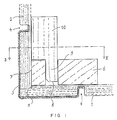
- FIG. 1 shows an embodiment of the present invention, in which a base plate 1 and a side plate 2 are connected to one another via a fastening clip 3.
- the fastening clip 3 engages at the ends of its legs in grooves 4 machined into the respective plates (second grooves).
- the side plate 2 is secured against tilting of the lower side wall edge towards the inside of the container by a shoulder 5 incorporated into the base plate 1.
- a continuous frame wood 6 is fastened on the base plate 1 along the edge of the plate in such a way that its end wall 7 abuts the side wall 2.
- the frame wood 6 can be attached to the surface of the base plate 1 by screwing, nailing, stapling or gluing.
- the material from which the frame wood 6 is made is preferably a sufficiently strong solid wood, such as pine, spruce or beech wood, or else Layered plywood.
- the panels are preferably made of plywood or a comparable composite material. The use of other materials is also conceivable.
- the frame wood 6 has, at regular intervals, which can preferably be between 0.5 to 1.5 m, grooves 8 (first grooves) which engage in the pins 9, which are incorporated in standing wood 10, which are arranged in a corresponding manner on the side wall 2 are attached.
- grooves 8 first grooves
- the pin 9 of the upright wood 10 is dimensioned such that it engages in the grooves 8 machined into the frame wood 6 and its length is slightly less than the thickness of the frame wood 6.
- at least one of the edges on the end face of the pin 9 is chamfered to a To facilitate insertion of the pin in the groove 8.
- the thickness of the pin is approximately half the width of the upright wood 10, so that in addition to the pin an approximately half the width of the upright wood is formed, which rests on the surface of the frame wood 6 when the pin is inserted.
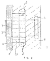
- Fig. 2 shows a horizontal section at the level of the line BB 'in Fig. 1. You can see on the left side Side wall 2 in section and the clamp 3 in engagement in the groove 4.
- the frame wood 6 abuts the side wall 2, into which grooves 8 are incorporated, into which the pins 9 of the sticks 10 engage.
- the pins are preferably bevelled on their lower edge pointing towards the side wall, which simplifies their introduction.
- the uprights 10 and the grooves 8 are arranged approximately at a lateral distance of 50 cm to 1.50 m in the above-mentioned transport containers. The spacing depends on the expected load.
- side walls can be attached to a base plate, which no longer have to be held in a vertical position until the fastening clips 3 are attached.
- a force acting from the inside on the side walls is now primarily absorbed by the uprights 10 and the frame wood 6 before it leads to a lateral load on the cranking of the fastening clips 3 in the grooves 4. This prevents grinding of the groove edges, so that the fastening clamps 3 are always securely seated in the grooves 4.
Landscapes
- Engineering & Computer Science (AREA)
- Life Sciences & Earth Sciences (AREA)
- Wood Science & Technology (AREA)
- Mechanical Engineering (AREA)
- Rigid Containers With Two Or More Constituent Elements (AREA)
- Packages (AREA)
- Containers Having Bodies Formed In One Piece (AREA)
- Cartons (AREA)
Description
- Die vorliegende Erfindung betrifft einen zusammenlegbaren Behälter nach dem Oberbegriff des Anspruchs 1. Ein solcher Behälter ist beispielsweise aus der US-A-3 476 279 bekannt.
- Ein bekannter Behälter verwendet rechteckige Platten, insbesondere aus Sperrholz, Holz oder einem anderen Verbundmaterial, die mit den bewährten Clip-Lok-Befestigungsklammern zusammengehalten werden. Die Klammern haben zueinander im rechten Winkel angeordnete Schenkel und werden an den Kanten des Behälters angebracht, wo die Enden der Befestigungsklammerschenkel in in den Platten zu diesem Zweck vorgesehene Nuten einrasten. Die Handhabung dieser Klammern, d. h. deren Anbringung und deren Lösen, geht sehr einfach vonstatten, so daß solche Behälter sehr schnell aufgebaut und auch wieder zerlegt werden können.
- Solche zusammenlegbaren Behälter haben sich in erster Linie für Transportaufgaben als konkurrenzlos nützlich erwiesen, bei denen vor Beschädigungen und äußeren Einwirkungen zu schützende Waren ständig von einem bestimmten Ort aus zu bestimmten Abnehmern geliefert werden, die die leeren Behälter im zusammengelegten Zustand an den Absender zurücktransportieren. Die zu transportierenden Güter können insbesondere in der metallverarbeitenden Industrie ein hohes Gewicht einnehmen, so daß neben der Einwirkung von äußeren Kräften auf die Transportkisten auch eine Druckbelastung der Behälterwände von innen her durch ein Verschieben der Last oder durch den Andruck von Halterungsgestellen auf die Seitenwände berücksichtigt werden muß. Diese Beanspruchung wird derzeit lediglich durch die Befestigungsklammern aufgefangen. Diese geben die mechanischen Stöße aus dem Inneren des Behälters über die Endbereiche ihrer Schenkel an die in die entsprechenden Platten eingearbeiteten Nuten weiter, die langfristig dadurch verformt werden können. Es ist somit denkbar, daß eine sichere Halterung der Befestigungsklammern in den Nuten somit nicht mehr gewährleistet ist.
- Die US-A-3 476 279 beschreibt einen zusammenlegbaren Behälter aus rechteckigen Platten, die durch Befestigungsklammern zusammengehalten werden, wobei entlang der Ränder der Bodenplatte und/oder der Deckelplatte und an dieser bzw. diesen befestigt jeweils ein an die Seitenwände anstoßendes durchgehendes Rahmenholz vorgesehen ist bzw. sind, in das bzw. die parallel zu den jeweiligen Rändern verlaufende Nuten eingearbeitet sind, in die wiederum entsprechend breite Zapfen eingreifen, die an jeweils auf entsprechender Höhe an den Seitenwänden befestigten Steherhölzern ausgebildet sind.
- Der vorliegenden Erfindung liegt die Aufgabe zugrunde, einen zusammenlegbaren Behälter der im Oberbegriff des Anspruchs 1 angegebenen Art derart weiterzuentwickeln, daß eine Kräftebeanspruchung der Befestigungsklammern vom Inneren des Behälters her sicher aufgefangen werden kann und die zusammenlegbaren Behälter insgesamt an Stabilität gewinnen.
- Diese Aufgabe wird mit den Merkmalen des Anspruchs 1 gelöst.
- In den Unteransprüchen sind bevorzugte Ausführungsformen der vorliegenden Erfindung beschrieben.
- Der erfindungsgemäße zusammenlegbare Behälter weist ferner den Vorteil auf, daß beim Zusammenbau eines Behälters die Seitenwände bereits über die in den Steherhölzern vorgesehenen Zapfen und durch das auf der Bodenplatte vorgesehene durchgehende Rahmenholz mit den entsprechenden Schlitzen ineinandergesteckt werden können und in dieser Stellung stehenbleiben, bevor die Befestigungsklammern angebracht sind.
- Dies spart Arbeitskräfte ein, da die erste an der Bodenplatte befestigte Seitenwand nicht mehr so lange in vertikaler Stellung gehaltert werden muß bis durch die Anbringung von Befestigungsklammern eine hinreichende Stabilität erreicht worden ist.
- Im folgenden wird ein Ausführungsbeispielder Erfindung anhand der Zeichnung näher erläutert. Darin zeigen
- Fig. 1
- einen vertikalen Schnitt durch eine untere Behälterkante mit dem ebenfalls geschnittenen Steherholz und dem Rahmenholz, und
- Fig. 2
- einen horizontalen Schnitt entlang der Linie B-B' in Fig. 1.
- Fig. 1 zeigt eine Ausführungsform der vorliegenden Erfindung, bei der eine Bodenplatte 1 und eine Seitenplatte 2 über eine Befestigungsklammer 3 miteinander verbunden sind. Die Befestigungsklammer 3 greift an den Enden ihrer Schenkel in in die jeweiligen Platten eingearbeitete Nuten 4 (zweite Nuten) ein.
- Die Seitenplatte 2 ist durch eine in die Bodenplatte 1 eingearbeitete Schulter 5 gegen ein Verkippen des unteren Seitenwandrandes zum Inneren des Behälters hin gesichert.
- Auf der Bodenplatte 1 ist entlang des Plattenrandes ein durchgehendes Rahmenholz 6 so befestigt, daß dieser mit seiner Stirnwand 7 gegen die Seitenwand 2 anstößt. Die Befestigung des Rahmenholzes 6 auf der Oberfläche der Bodenplatte 1 kann durch Verschrauben, Nageln, Klammern oder Verleimen erfolgen. Das Material, aus dem das Rahmenholz 6 gefertigt ist, ist vorzugsweise ein ausreichend festes Massivholz, wie Kiefern-, Fichten- oder Buchenholz oder auch Schichtsperrholz. Die Platten sind vorzugsweise aus Sperrholz oder einem vergleichbaren Verbundmaterial. Die Verwendung anderer Materialien ist ebenso denkbar.
- Eine analoge Anordnung eines durchgehenden Rahmenholzes auf der Deckelunterseite des Behälters mit entsprechenden Zapfenhölzern an den Seitenwänden ist ebenfalls möglich. Die dadurch erzielte Versteifung wirkt sich insbesondere bei Schnittgütern aus, wo die Belastung der Seitenwände eines Behälters besonders stark ist.
- Das Rahmenholz 6 weist in regelmäßigen Abständen, die vorzugsweise zwischen 0,5 bis 1,5 m betragen können, Nuten 8 (erste Nuten) auf, in die Zapfen 9 eingreifen, die in Steherhölzer 10 eingearbeitet sind, die in entsprechender Anordnung an der Seitenwand 2 befestigt sind. Für die Befestigung der Steherhölzer 10 an der Seitenwand 2 gilt das bereits zum Rahmenholz 6 gesagte entsprechend. Der Zapfen 9 des Steherholzes 10 ist so dimensioniert, daß er in die in das Rahmenholz 6 eingearbeiteten Nuten 8 eingreift und seine Länge liegt geringfügig unter der Dicke des Rahmenholzes 6. Ferner ist mindestens eine der Kanten an der Stirnseite des Zapfens 9 abgeschrägt, um ein Einfügen des Zapfens in die Nut 8 zu erleichtern. Die Dicke des Zapfens beträgt etwa die halbe Breite des Steherholzes 10, so daß neben dem Zapfen eine ebenfalls etwa die halbe Breite des Steherholzes einnehmende Schulter ausgebildet ist, die bei eingestecktem Zapfen auf der Oberfläche des Rahmenholzes 6 ruht.
- Fig. 2 zeigt einen horizontalen Schnitt auf der Höhe der Linie B-B' in Fig. 1. Man erkennt auf der linken Seite die Seitenwand 2 im Schnitt sowie die Klammer 3 im Eingriff in die Nut 4. An die Seitenwand 2 stößt das Rahmenholz 6 an, in das Nuten 8 eingearbeitet sind, in die die Zapfen 9 der Steherhölzer 10 eingreifen. Unterhalb der Bodenplatte 1 ist gestrichelt der zweite Schenkel der Befestigungsklammer 3 sowie die Nut 4, in die dessen Kröpfung eingreift, eingezeichnet. Die Zapfen sind vorzugsweise an ihrer zur Seitenwand hinweisenden Unterkante abgeschrägt, was deren Einführung vereinfacht.
- Die Steherhölzer 10 sowie die Nuten 8 werden bei den eingangs erwähnten Transportbehältern etwa in einem seitlichen Abstand von 50 cm bis 1,50 m angeordnet. Die Beabstandung hängt von der zu erwartenden Beanspruchung ab.
- Durch das Vorsehen der Rahmenhölzer können neuerungsgemäß Seitenwände an einer Bodenplatte angebracht werden, die nicht mehr in vertikaler Lage festgehalten werden müssen, bis die Befestigungsklammern 3 angebracht sind. Eine von innen auf die Seitenwände einwirkende Kraft wird nunmehr in erster Linie von den Steherhölzern 10 und den Rahmenhölzern 6 abgefangen, bevor sie zu einer seitlichen Belastung der Kröpfung der Befestigungsklammern 3 in den Nuten 4 führt. Dadurch wird einem Abschleifen der Nutkanten vorgebeugt, so daß ein stets sicherer Sitz der Befestigungsklammern 3 in den Nuten 4 gewährleistet wird.
Claims (5)
- Zusammenlegbarer Behälter aus rechteckigen Platten (12), die durch Befestigungsklammern (3) zusammengehalten werden, wobei
entlang der Ränder der Bodenplatte (1) und/oder der Deckelplatte und an dieser bzw. diesen befestigt jeweils ein an die Seitenwände (2) anstoßendes durchgehendes Rahmenholz (6) vorgesehen ist bzw. sind, in das bzw. die parallel zu den jeweiligen Rändern verlaufende erste Nuten (8) eingearbeitet sind, in die wiederum entsprechend breite Zapfen eingreifen, die an jeweils auf entsprechender Höhe an den Seitenwänden (2) befestigten Steherhölzern (10) ausgebildet sind,
dadurch gekennzeichnet,
daß die Befestigungsklammern mit vorbestimmten Abständen entlang der Kanten des Behälters angeordnet sind und in zweite Nuten (4) eingreifen, die in die Seitenwände sowie Boden- und Deckelplatten eingearbeitet sind, wobei die ersten Nuten (8) jeweils auf der gleichen Höhe an der Bodenplatte (1) bzw. der Deckelplatte angebracht sind, auf der sich auch die zweiten Nuten (4) und die in diese eingreifenden Befestigungsklammern (3) befinden. - Behälter nach Anspruch 1,
dadurch gekennzeichnet,
daß die Zapfen der Steherhölzer (10) etwa halb so dick sind wie die Gesamtdicke der Steherhölzer (10) und deren Eingrifftiefe etwa 0,5 cm weniger als die Dicke des Rahmenholzes (6) beträgt. - Behälter nach Anspruch 2,
dadurch gekennzeichnet,
daß der Zapfen (9) an mindestens einer Kante seines Einführendes abgeschrägt ist. - Behälter nach einem der Ansprüche 1 bis 3,
dadurch gekennzeichnet,
daß die Rahmen- bzw. Steherhölzer (6, 10) mit der Bodenplatte (1), der Deckelplatte bzw. mit der jeweiligen Seitenwand (2) verschraubt, verleimt oder durch Klammern oder Nägel verbunden sind. - Behälter nach einem der Ansprüche 1 bis 4,
dadurch gekennzeichnet,
daß die Rahmen- bzw. Steherhölzer (6, 10) aus Fichtenholz, Kiefernholz, Buchenholz oder Schichtsperrholz sind.
Applications Claiming Priority (2)
| Application Number | Priority Date | Filing Date | Title |
|---|---|---|---|
| DE9005181U | 1990-05-07 | ||
| DE9005181U DE9005181U1 (de) | 1990-05-07 | 1990-05-07 | Zusammenlegbarer Behälter |
Publications (2)
| Publication Number | Publication Date |
|---|---|
| EP0455875A1 EP0455875A1 (de) | 1991-11-13 |
| EP0455875B1 true EP0455875B1 (de) | 1995-03-08 |
Family
ID=6853581
Family Applications (1)
| Application Number | Title | Priority Date | Filing Date |
|---|---|---|---|
| EP90124229A Expired - Lifetime EP0455875B1 (de) | 1990-05-07 | 1990-12-14 | Zusammenlegbarer Behälter |
Country Status (4)
| Country | Link |
|---|---|
| EP (1) | EP0455875B1 (de) |
| AT (1) | ATE119488T1 (de) |
| DE (2) | DE9005181U1 (de) |
| ES (1) | ES2071734T3 (de) |
Cited By (2)
| Publication number | Priority date | Publication date | Assignee | Title |
|---|---|---|---|---|
| US11731805B2 (en) | 2021-01-22 | 2023-08-22 | PRO blanket bars GmbH | Collapsible containers including attachment brackets |
| US12397986B2 (en) | 2021-01-22 | 2025-08-26 | PRO blanket bars GmbH | Collapsible containers including edge attachment brackets |
Families Citing this family (4)
| Publication number | Priority date | Publication date | Assignee | Title |
|---|---|---|---|---|
| EP0650899B1 (de) * | 1993-10-27 | 1998-05-20 | Volkswagen Aktiengesellschaft | Zusammenfaltbare Behälter |
| DE4415638C2 (de) * | 1994-05-04 | 2002-07-18 | Wagner & Keller Gmbh & Co | Klappbarer Rahmen für eine Transport- oder Lagerbox |
| SE513685C2 (sv) * | 1998-01-28 | 2000-10-23 | Nefab Ab | Anordning för inbördes låsning av två delar |
| ES1066288Y (es) * | 2007-09-13 | 2008-04-01 | Encaja Embalajes De Madera S L | Caja montable, desmontable y reutlizable |
Family Cites Families (5)
| Publication number | Priority date | Publication date | Assignee | Title |
|---|---|---|---|---|
| FR548544A (fr) * | 1922-01-06 | 1923-01-17 | Emballage démontable en bois pour fruits et primeurs | |
| GB393075A (en) * | 1932-01-21 | 1933-06-01 | Karl Michaelis | Improvements in and relating to collapsible boxes, crates and like containers |
| FR2424193A2 (fr) * | 1978-04-26 | 1979-11-23 | Petit Rene | Caisse pliable, notamment sous forme de caisse-palette |
| DE3046954A1 (de) * | 1980-12-12 | 1982-07-15 | AKUTEC Angewandte Kunststofftechnik GmbH, 8000 München | Faltkiste |
| DE8913011U1 (de) * | 1989-11-03 | 1989-12-28 | Schollmayer, Valentin, 6503 Mainz-Kastel | Kastenförmiger Verpackungsbehälter mit Verbindungselementen zum Verbinden aneinandergrenzender Behälterwände |
-
1990
- 1990-05-07 DE DE9005181U patent/DE9005181U1/de not_active Expired - Lifetime
- 1990-12-14 ES ES90124229T patent/ES2071734T3/es not_active Expired - Lifetime
- 1990-12-14 DE DE59008665T patent/DE59008665D1/de not_active Expired - Fee Related
- 1990-12-14 EP EP90124229A patent/EP0455875B1/de not_active Expired - Lifetime
- 1990-12-14 AT AT90124229T patent/ATE119488T1/de active
Cited By (2)
| Publication number | Priority date | Publication date | Assignee | Title |
|---|---|---|---|---|
| US11731805B2 (en) | 2021-01-22 | 2023-08-22 | PRO blanket bars GmbH | Collapsible containers including attachment brackets |
| US12397986B2 (en) | 2021-01-22 | 2025-08-26 | PRO blanket bars GmbH | Collapsible containers including edge attachment brackets |
Also Published As
| Publication number | Publication date |
|---|---|
| ES2071734T3 (es) | 1995-07-01 |
| ATE119488T1 (de) | 1995-03-15 |
| DE59008665D1 (de) | 1995-04-13 |
| EP0455875A1 (de) | 1991-11-13 |
| DE9005181U1 (de) | 1990-07-12 |
Similar Documents
| Publication | Publication Date | Title |
|---|---|---|
| DE1761869B2 (de) | Vorrichtung fuer die einlagerung, die handhabung und den transport von stapeln zerbrechlicher platten | |
| EP2981486B1 (de) | Containerstausystem | |
| DE202015005791U1 (de) | Transport- und/oder Lagergestell | |
| DE102013013461C5 (de) | Stoß- oder Eckverbindung von aneinander gefügten Teilen und Verpackungskiste mit einer Schwalbenschwanzzapfen-Verbindung | |
| DE1298440B (de) | Zerlegbare Kiste | |
| EP0455875B1 (de) | Zusammenlegbarer Behälter | |
| EP0357817B1 (de) | Holzregal mit auf unterschiedlichen Höhen anbringbaren Einlegeböden | |
| DE202016006174U1 (de) | Eckverbindung dreier balkenförmiger Elemente, Verbindungselement und Lager-, Transport- oder Rahmengestell oder Skelettrahmen | |
| EP1882641B1 (de) | Transportpalette | |
| DE4024123C1 (de) | ||
| WO2001004010A1 (de) | Palette zur aufnahme einer last, insbesondere eines zweirads | |
| DE1511553A1 (de) | Verpackung fuer einen rechteckigen Stapel aus mehreren Platten | |
| DE2549252C2 (de) | ||
| DE102014109323B4 (de) | Mehrweg-Transportbox | |
| DE9304036U1 (de) | Transportbehälter | |
| DE8305623U1 (de) | Geruestbohle | |
| DE102016104262B3 (de) | Mehrweg-Transportbox | |
| DE202011106430U1 (de) | Behälter | |
| DE9209526U1 (de) | Warenträger | |
| DE2532362A1 (de) | Gleitunterbauten oder paletten und verfahren zu deren anbringen am boden eines containers | |
| DE2032220A1 (de) | Palette, bestehend aus mindestens zwei Holmen, die mit quer zu den Holmen verlaufenden Brettern oder dgl. verbunden sind | |
| DE9100014U1 (de) | Transportpalette | |
| DE8808808U1 (de) | Transportkiste mit Einsatz | |
| DE60301120T2 (de) | Zusammensetzung aus lösbaren Teilpaletten | |
| DE202014100432U1 (de) | Transportbehälter |
Legal Events
| Date | Code | Title | Description |
|---|---|---|---|
| PUAI | Public reference made under article 153(3) epc to a published international application that has entered the european phase |
Free format text: ORIGINAL CODE: 0009012 |
|
| AK | Designated contracting states |
Kind code of ref document: A1 Designated state(s): AT BE CH DE ES FR GB IT LI NL |
|
| 17P | Request for examination filed |
Effective date: 19920506 |
|
| 17Q | First examination report despatched |
Effective date: 19930118 |
|
| RAP1 | Party data changed (applicant data changed or rights of an application transferred) |
Owner name: FRITZ NEIDHART GMBH & CO. KG HOLZWERKE |
|
| GRAA | (expected) grant |
Free format text: ORIGINAL CODE: 0009210 |
|
| AK | Designated contracting states |
Kind code of ref document: B1 Designated state(s): AT BE CH DE ES FR GB IT LI NL |
|
| REF | Corresponds to: |
Ref document number: 119488 Country of ref document: AT Date of ref document: 19950315 Kind code of ref document: T |
|
| ITF | It: translation for a ep patent filed | ||
| ET | Fr: translation filed | ||
| GBT | Gb: translation of ep patent filed (gb section 77(6)(a)/1977) |
Effective date: 19950313 |
|
| REF | Corresponds to: |
Ref document number: 59008665 Country of ref document: DE Date of ref document: 19950413 |
|
| REG | Reference to a national code |
Ref country code: ES Ref legal event code: FG2A Ref document number: 2071734 Country of ref document: ES Kind code of ref document: T3 |
|
| PGFP | Annual fee paid to national office [announced via postgrant information from national office to epo] |
Ref country code: FR Payment date: 19951213 Year of fee payment: 6 |
|
| PGFP | Annual fee paid to national office [announced via postgrant information from national office to epo] |
Ref country code: ES Payment date: 19951215 Year of fee payment: 6 Ref country code: AT Payment date: 19951215 Year of fee payment: 6 |
|
| PG25 | Lapsed in a contracting state [announced via postgrant information from national office to epo] |
Ref country code: LI Effective date: 19951231 Ref country code: CH Effective date: 19951231 |
|
| PLBE | No opposition filed within time limit |
Free format text: ORIGINAL CODE: 0009261 |
|
| STAA | Information on the status of an ep patent application or granted ep patent |
Free format text: STATUS: NO OPPOSITION FILED WITHIN TIME LIMIT |
|
| 26N | No opposition filed | ||
| PG25 | Lapsed in a contracting state [announced via postgrant information from national office to epo] |
Ref country code: NL Effective date: 19960701 |
|
| REG | Reference to a national code |
Ref country code: CH Ref legal event code: PL |
|
| NLV4 | Nl: lapsed or anulled due to non-payment of the annual fee |
Effective date: 19960701 |
|
| PGFP | Annual fee paid to national office [announced via postgrant information from national office to epo] |
Ref country code: GB Payment date: 19961210 Year of fee payment: 7 |
|
| PG25 | Lapsed in a contracting state [announced via postgrant information from national office to epo] |
Ref country code: AT Effective date: 19961214 |
|
| PGFP | Annual fee paid to national office [announced via postgrant information from national office to epo] |
Ref country code: BE Payment date: 19970217 Year of fee payment: 7 |
|
| PG25 | Lapsed in a contracting state [announced via postgrant information from national office to epo] |
Ref country code: FR Effective date: 19970829 |
|
| REG | Reference to a national code |
Ref country code: FR Ref legal event code: ST |
|
| PG25 | Lapsed in a contracting state [announced via postgrant information from national office to epo] |
Ref country code: GB Free format text: LAPSE BECAUSE OF NON-PAYMENT OF DUE FEES Effective date: 19971214 |
|
| PG25 | Lapsed in a contracting state [announced via postgrant information from national office to epo] |
Ref country code: ES Free format text: LAPSE BECAUSE OF NON-PAYMENT OF DUE FEES Effective date: 19971215 |
|
| PG25 | Lapsed in a contracting state [announced via postgrant information from national office to epo] |
Ref country code: BE Free format text: LAPSE BECAUSE OF NON-PAYMENT OF DUE FEES Effective date: 19971231 |
|
| BERE | Be: lapsed |
Owner name: FRITZ NEIDHART G.M.B.H. & CO. K.G. HOLZWERKE Effective date: 19971231 |
|
| GBPC | Gb: european patent ceased through non-payment of renewal fee |
Effective date: 19971214 |
|
| PGFP | Annual fee paid to national office [announced via postgrant information from national office to epo] |
Ref country code: DE Payment date: 20030227 Year of fee payment: 13 |
|
| REG | Reference to a national code |
Ref country code: ES Ref legal event code: FD2A Effective date: 19980113 |
|
| PG25 | Lapsed in a contracting state [announced via postgrant information from national office to epo] |
Ref country code: DE Free format text: LAPSE BECAUSE OF NON-PAYMENT OF DUE FEES Effective date: 20040701 |
|
| PG25 | Lapsed in a contracting state [announced via postgrant information from national office to epo] |
Ref country code: IT Free format text: LAPSE BECAUSE OF NON-PAYMENT OF DUE FEES;WARNING: LAPSES OF ITALIAN PATENTS WITH EFFECTIVE DATE BEFORE 2007 MAY HAVE OCCURRED AT ANY TIME BEFORE 2007. THE CORRECT EFFECTIVE DATE MAY BE DIFFERENT FROM THE ONE RECORDED. Effective date: 20051214 |