EP0453543B2 - Automatisches strumpfwendegerät für eine kettelmaschine - Google Patents
Automatisches strumpfwendegerät für eine kettelmaschine Download PDFInfo
- Publication number
- EP0453543B2 EP0453543B2 EP90916734A EP90916734A EP0453543B2 EP 0453543 B2 EP0453543 B2 EP 0453543B2 EP 90916734 A EP90916734 A EP 90916734A EP 90916734 A EP90916734 A EP 90916734A EP 0453543 B2 EP0453543 B2 EP 0453543B2
- Authority
- EP
- European Patent Office
- Prior art keywords
- stocking
- belts
- turning
- gripper
- photocell
- Prior art date
- Legal status (The legal status is an assumption and is not a legal conclusion. Google has not performed a legal analysis and makes no representation as to the accuracy of the status listed.)
- Expired - Lifetime
Links
Images


Classifications
-
- D—TEXTILES; PAPER
- D06—TREATMENT OF TEXTILES OR THE LIKE; LAUNDERING; FLEXIBLE MATERIALS NOT OTHERWISE PROVIDED FOR
- D06G—MECHANICAL OR PRESSURE CLEANING OF CARPETS, RUGS, SACKS, HIDES, OR OTHER SKIN OR TEXTILE ARTICLES OR FABRICS; TURNING INSIDE-OUT FLEXIBLE TUBULAR OR OTHER HOLLOW ARTICLES
- D06G3/00—Turning inside-out flexible tubular or other hollow articles
- D06G3/02—Turning inside-out flexible tubular or other hollow articles by mechanical means
Definitions
- the invention relates to an automatic hosiery turning device, that combined with a linking machine can be.
- hosiery turning devices are already known where a rod or a rail is provided is the tubular knitted fabric already closed by sewing at its tip Stockings pulled up and at the same time, starting from the tip, rotating in opposite directions with the help of a pair, parallel rollers that are turned elastically pressed the opposite sides of the rod (US-A 4 627 557).
- the invention is based on the object To make the hosiery device available which Compound with a warping machine works automatically and the mentioned disadvantages of the known systems avoids, taking effective measures to be in the correct position of the stocking during control the wedging process on the rod.
- the longitudinal guide elements is slidably mounted, which of the housing towards the dispensing zone with the to the hosiery machine stand out, the displacement of the carriage on the longitudinal guide elements of a pneumatic cylinder is controlled.
- the gripper with one Connected carriage, first jaw and a second Jaw has a pivot on the first
- the jaw is articulated, which is parallel to the vertical Shifting plane of the turning bar runs when the gripper is located between the two upper belts.
- the second jaw can be moved a pneumatic cylinder is used relative to the first jaw become.
- the first jaw of the gripper can be pivoted about a vertical axis of rotation connected to the sled so that it is between one essentially tangential to the circumferential line of the slewing ring the position of the warping machine and one parallel to the vertical displacement plane of the turning bar current position is pivotable.
- the Rotation of the first jaw relative to the carriage preferably controlled by a pneumatic cylinder.
- the stabilizer is a pair mutually identical, straight combs which is symmetrical on both sides of the vertical Shifting plane of the turning bar arranged and are attached to the upper end of support arms that also equally designed with each other and with both Sides of the vertical shift plane lie and to run obliquely downwards, the lower ones Ends are attached to axes of rotation.
- the support arms are moved by a pneumatic cylinder driven.
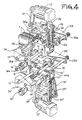
- An essential feature of the invention is in that the support structures for each band each Belt pair made of plate or cuboid bearing blocks exist that can be moved on horizontal guides stored and in pairs with a pantograph lever system which are connected via Pneumatic cylinder can be driven such that the bearing blocks during its adjustment movement with respect to the vertical Shifting plane of the turning bar always the same Have distances to this level. There are means to set the minimum distance between the Bearing blocks provided on which the respective Band pairs are stored.
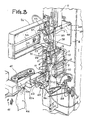
- a fixed housing 1 which for The turning device is accommodated and stored, whose turning organs are designated by 2.
- the turning organs 2 have an elongated turning bar 3, the free end of which faces down and the by means of a box-shaped guide 5 in front of the front wall 4 of the housing 1 is mounted so that it between an upper end position ( Figures 1 and 6) a lower End position ( Figure 9) can be moved.
- a pneumatic cylinder 6 on the box-shaped Guide 5 is attached.
- the bands are arranged symmetrically on this plane and have a distance in the "open" state to this level if the device has no function exercises.
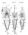
- the upper pair of bands 7 is at such a height arranged that it is between its levels, each other opposite dreams the lower end of the Turning stick 3 picks up when this is in its top position.
- the bands 7 and 8 are preferably made of one Made of elastomeric plastic with the lengthways running, inner steel fibers is reinforced. On their outside, which is in contact with the stocking fabric comes, the tapes have V-shaped transverse grooves, which extend across the entire width of the tapes.
- Each belt 7 and 8 is guided over two rollers 9 and 10, which are particularly good in Figures 6 to 10 recognize and are driven by a role is.
- the upper rollers 9 for the upper belts 7 and the lower rollers 8 for the lower belts 10 driven.
- the roller pairs 9, 10, over which the upper bands 7 run, are in each a bearing block 11 or 12 stored, the cuboid or is plate-shaped.
- the bearing blocks 11, 12 are slidably mounted on transverse axes 13 and 14, which is perpendicular to the vertical working plane of the turning bar 3 run, the bearing blocks 11 and 12 have the same distances from this level and by means of a pneumatic cylinder 15 this level at the same time can be approximated or removed from this.
- the required minimum distance between the two bearing blocks 11 and 12 and consequently between the directly opposite dreams of Bands 7 can be adjusted using a knob 16 with a scale ring can be set.
- FIG. 4 in which the distance between the top and bottom Band pair is drawn in excessively large to increase the clarity of the display.
- a motor is used 17, which is housed in the upper part of the housing 1 is. This drives on belts 18, 19 and 20 as well Gears 21 and 22 on the rollers 9.
- the corresponding one Drive for the rollers 10, via which the two lower ones Bands 8 run, is constructed in an analogous manner. The only difference is that the arrangement mirror-symmetrical to a horizontal plane is. For these reasons, the description is repeated waived, suffice it that the corresponding components have the same reference numbers with the addition of a prime.
- transverse axes 13, 14 and 13 ', 14' are in the housing 1 via C-shaped profile body 23, 24 or 23 ', 24' fixed.
- a lever system 25 or 25 'is provided which in essentially acts as a parallelogram link and with the associated bearing blocks 11 and 12 or 11 'and 12 'is connected.
- Figure 4 shows the upper bearing blocks 11 and 12 associated lever system 25, the is hinged to a fixed support bracket 25a.
- the adjusting knob 16 has a cam-shaped end face 16a with notches into which a finger 24a snap can, which is attached to the profile body 24, which is in turn fixed in the housing 1. If the Turn knob 16 clockwise according to arrow 16b is, the transverse axis 14 against the action of a Spring 23a are adjusted, which in turn tries the To shift the transverse axis 14 to the right (see FIG 4). This movement is via a lock nut 14 (in Figure 4 is the locknut 14'a for the lower system for lateral displacement of the bands 8 shown) on the Transfer bearing block 11.
- the transfer device for the acceptance of a turning stocking from the warping machine and to Forwarding to the turning organs is particularly in Figures 1, 2, 3 and 11 shown.
- This transfer device has a pincer-shaped Gripper 26 with two jaws 27 and 28, one over Pivots 29 pivotally mounted to each other are.
- the pivot 29 lies in a horizontal plane and extends in the longitudinal direction of the gripper 26, so that the opposing gripping edges 27 'and 28' of the jaws in a horizontal plane lie.
- the gripper 26 is normally operated by a spring 30 held in its closed position.
- This Spring 30 is in an area above the pivot 29 inserted between the two jaws 27 and 28. Is located below the two jaws 27 and 28 a pneumatic cylinder 31, which is used to open the gripper 26 serves.
- the jaw 27 of the gripper 26 is fixed to one Support arm 32 attached to the side of the lower end of a slide 33 protrudes.
- the carriage 33 is on two horizontal longitudinal guide elements 34 and 35 slidably stored parallel to the vertical working plane run in which the turning bar 3 moves.
- the longitudinal guide elements 34 and 35 are in one Console 36 attached to the side of the pairs of bands 7 and 8 on the front wall 4 of the housing 1 is attached.
- a pneumatic cylinder 37 in the housing 1 housed the carriage 33 on the longitudinal guide elements 34 and 35 moves so that the gripper 26 on a predetermined straight path between one with respect to the turning organs 3, 7, 8 outer Position and an inner position is shifted in which is located between the upper bands 7, the opposing, interacting Gripping edges 27 'and 28' of the two jaws 27 and 28 parallel to the vertical working plane of the turning bar 3 lie.
- the parts are dimensioned so that in the latter position, the gripping edge 27 'of on the support arm 32 attached jaw 27 something about this vertical working level protrudes into one of the console 36 pioneering direction.
- the gripper 26 When the gripper 26 is in the outer position is located, it is above the delivery zone 40 of the straight line trained warping machine 41 (see FIG. 1 and 3).
- the stockings with the laces already sewn on, which are already trimmed or sewn are in the delivery zone 40 brought by a conveyor belt 42, that works with a carriage 42a, the by two springs, not shown, against the conveyor belt 42 is pressed.
- a pneumatic cylinder 42b To the carriage 42a of To remove the conveyor belt 42 is a pneumatic cylinder 42b provided.
- the gripper 26 comes open in this position, and that of the conveyor belt 42 stocking fed towards the turning device stops as soon as he the with respect to the gripper 26 has reached the correct position.
- “Correct position” means the situation which ensures that after closing of the gripper 26 and its displacement in the direction the “inner position” is that shown in FIG Sack S in the top of the stocking next to the Seam area is formed and still closed by the gripper is held with respect to the lower end of the Turning bar 3 is centered (the vertical longitudinal median plane of the turning bar 3 coincides with the vertical longitudinal median plane of the two pairs of bands 7 and 8 together). This condition must be met in order to subsequently use the To be able to turn your stocking flawlessly and without problems.
- a stabilizing device which has the task of aligned position of the stocking during the turning process to control. It has two combs 46 which are equally designed and symmetrical to each other on both sides of the vertical working plane of the turning bar 3 are arranged. They extend at right angles to the front wall 4 of the housing 1 and are on attached upper end of two support arms 47, which also equal to each other and to the vertical mentioned Working plane are arranged symmetrically. The both support arms 47 are slightly spread upwards, and their lower ends are each about an axis of rotation 48 swivel-mounted, the right angle to the front wall 4 runs.
- pneumatic cylinder 49, 50 actuated in Housing 1 is housed and the two support arms 47 in the desired direction about its respective axis of rotation 48 pivots.
- the smallest distance between the two combs 46 can be set via a device which is constructed similarly to the one with whose help the minimum distance between bands 7 and 8 is set becomes.
- Figure 5 shows that this device Rod 51 has an adjusting knob 52 attached is, which is outside the housing 1 and the front is designed as a cam 53 with notches in which a finger 54 can snap into place, which is attached to the housing 1 is.
- a spring 55 pushes the rod 51 in the direction the left edge of Figure 5.
- One on the rod 51 attached locknut 56 acts on the right arm 47 in the sense that she tries to get him from the left To remove support arm 47. On this the swivel movement transmitted over tooth sectors 57 which on the axes of rotation 48 are mounted.
- the hosiery device with one programmable control unit 59 which with the magnetic sensors 38 and 39, with the photocells 43 and 58, with motors 17 and 17 'as well connected to all pneumatic cylinders explained above is.
- this control unit 59 can coordinate the functions of these elements be the turning cycles for the stockings by come from the chaining machine, perform smoothly to be able to.
- the displacement of the slide 33 has ended, as soon as the gripper 26 between the two upper bands 7, the stocking 44 between the two lower bands 8 hangs and the Combs 46 assume an open position (see FIG 6). Due to the fact that the sack S, which is next to the top of the stocking gripped by the gripper 26 44 lies, i.e. to the side of the vertical work plane of the turning bar 3, and due to the centered position the tip is located with respect to the jaws 27 and 28 the sack S is just below the lower end of the Turning stick 3. The stocking 44 darkens the photocell 58, which is inactive in this phase.
- the stabilizer provides with the combs 46 for the stocking during excited about his upward movement remains so that it will stretch if it turns or would kink, so that jamming or tilting the turning bar 3 in the cavity the heel or in the doubled, elastic, free Edge of the leg part of the stocking is prevented.
- the belts 7 rotate and 8 further in the direction of the arrows, see above that the stocking is pushed up on the turning bar 3 becomes.
- the control unit 59 sets the following functions in motion become.
- the advantages of the hosiery device according to the Invention are due to the special properties numerous and of special, practical importance. Because the diameter of the rolls over which the tapes run, can be relatively small (e.g. 34 mm), is the one clamped between the lower bands 8 Stocking little over the top of the Clamping zone (in practice about 22 mm), so that there is no danger that he can lean to the side, which is why the downward turning bar 3 is safe enters the sack, which is on one side of the sewn on Top of the stocking is located.
- the contact zone between the two gripping edges 27 ', 28' of Baking the closed gripper 26 on one side the vertical working plane of the turning bar 3 is located (generally 5 mm laterally offset to this Level), it is ensured that the turning bar 3 always enters this sack exactly, even if the turning device combined with a straight-line warping machine is, then the sack from the belt conveyor is held until the looper sews the tip of the Stockings captured.
- V-shaped Have cross grooves so that stockings with very loose stitches are not damaged when turning, because the continuous quemutes worked loosely Can neither grasp nor remove threads.
- the time required for a turning operation is relatively short, because the turning bar 3 during its movement between the upper and the lower End position does not stop. Because the lower Bands 8 that are involved in the turning process, too serve to pull the stocking down and to reverse their direction of rotation, it is ensured that no friction acts on the stocking, what before excludes all damage to terry socks.
- the turning bar stops as it moves down 3 in such a position that its lower End located below the lower bands 8. That has the advantage that the lower bands 8 are not on the area act on the sewn tip of the stocking, but only on the foot area. In this is namely the opposite direction of the stitches of those in the top of the stocking, so that in the one below Part of the danger is avoided that the Mesh of a terry sock be raised.
- both bands each pair are driven because this makes each relative Avoid shifting the height of the hosiery is, which are located on both sides of the turning bar 3.
- the fixed connection between the combs 46 and its support arms 47 allows the stocking to always be well tensioned and during the turning process keep exactly aligned, avoiding the danger is that the turning bar 3 in the heel or canted in the upper edge of the leg part of the stocking or jammed if the stockings are double elastic or the upper margin is double. Simultaneously relieved the drive of the support arms carrying the combs 47 by means of a pneumatic cylinder of the hosiery device on stockings different Thick.
- the hosiery device according to the invention can also be used to turn children's stockings if they have a length that of the combs 46 can be held.
- the device can however easily on stockings of small sizes up to one Minimum length of 18 cm can be adjusted. This is enough it is to remove the photocell 58 and the To program the control unit so that the time for one Turning process is fixed, including the downward stroke of the turning bar 3 reduced accordingly and the combs 46 approximate the lower bands 8 become.
- Removing the stocking that has already been turned downwards is favored by the fact that the upper Bands 7 that are at the beginning of the cycle in the same Turn direction like the lower bands 8 during the Withdrawal phase is stopped and thereby the downward movement brake the stocking slightly.
- the upper bands 7 and the lower bands 8 are simultaneously towards the vertical working plane the turning bar 3 moved and withdrawn from this plane, for which each pair of belts with a pneumatic cylinder connected is.
- This measure can the minimum distance of the tapes from the above Level can be set easily and very precisely, so that the hosiery device easily and precisely to the treatment adapted from stockings of different thicknesses can be without special training Personnel is required.
- the one for this setting required operation is so simple that it can be carried out by any operator can that on the linking machine and the hosiery device is working. It is enough for each pair of bands just turn the corresponding knob, which is graded and easily accessible is. In this way, the smallest distance between the tapes from the vertical working plane of the turning bar 3 can be set with micrometer accuracy.
- the hosiery device with the explained features and advantages is extremely reliable, very adaptable and easy to operate, so that not itself specially trained personnel can.
- the jaw 27 'of the gripper 26' is not rigidly attached to the support arm 32 of the carriage 33, but pivotable about a vertical axis of rotation 60.
- the gripper 26 'in the direction of the turning organs it is moved by a pneumatic cylinder 61 a position shown in broken lines in FIG. 11, in which he removes the stocking from the needles 62 of the slewing ring the linking machine 41 'takes over into one position rotated, which is essentially parallel to the vertical working plane of the turning bar 3 runs and in Figure 11 is drawn with solid lines.
- the gripping edges of the two grasping the stocking Jaws 27 'and 28' are curved in this case formed, the curvature to the circular arc shape the turntable of the needles 62 is adapted.
- the plate 45 which is the photocell 43 carries, curved (not shown in Figure 11), so that the adjustment of the position of the photocell 43 to the width of the stocking in that the plate 45th with the photocell in the circumferential direction of the slewing ring 62 is adjusted.
- Another variant can be that the Pneumatic cylinder 6, which is used to drive the turning bar 3 is provided, with magnetic sensors 63, 64 and 65 is equipped (see FIG. 1), which of the control unit 59 report when turning stick 3 reaches its top reached its lowest and middle position Has.
- the carriage can also 33 controlling pneumatic cylinders 37 a middle one Have magnetic sensor 66.
- the magnetic sensors provided in the middle area 65 and 66 have the advantage that they have the control unit 59 initiate certain functions, before the gripper 26 and / or the turning bar 3 the has reached the respective end position.
Landscapes
- Engineering & Computer Science (AREA)
- Mechanical Engineering (AREA)
- Textile Engineering (AREA)
- Treatment Of Fiber Materials (AREA)
- Sewing Machines And Sewing (AREA)
Description
- Figur 1
- eine perspektivische Vorderansicht eines Strumpfwendegerätes gemäß der Erfindung zu Beginn eines Arbeitszyklus, das mit einer Kettelmaschine geradliniger Bauart gekoppelt ist,
- Figur 2
- die vergrößerte Ansicht eines Greifers für die Übergabe der Strümpfe,
- Figur 3
- eine vergrößerte Ausschnittsdarstellung der Figur 1 bei einem weiteren Arbeitsschritt,
- Figur 4
- die perspektivische Darstellung des Lagerungs- und Bewegungssystems für die oberen und unteren Bandpaare,
- Figur 5
- die Seitenansicht zur Darstellung des Antriebssystems für die Tragarme der Kämme der Stabilisierungseinrichtung, welches die genaue Lage des Strumpfes beim Wenden sichert,
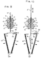
- Figuren 6 bis 10
- schematische Darstellungen der Bearbeitungsfolge beim Wenden eines Strumpfes mit Hilfe der oberen und unteren Bandpaare sowie des höhenverstellbaren Stabes und
- Figur 11
- eine Draufsicht auf einen Teil des Strumpfwendegerätes gemäß der Erfindung, das mit einer kreisförmigen Kettelmaschine kombiniert ist.
Claims (22)
- Automatisches Strumpfwendegerät, das mit einer Kettelmaschine kombinierbar ist, mit:dadurch gekennzeichnet,Wendeorganen (3, 7, 8), die von einem Gehäuse (1) getragen werden und umfassen:einen vertikalen Wendestab (3), dessen freies Ende nach unten weist,ein erstes Paar oberer (7) und ein zweites Paar unterer (8), geschlossener, in Längsrichtung umlaufender Bänder, deren ebene Trume parallel zur verikalen Arbeitsebene- und Verschiebeebene des Wendestabes (3) verlaufen, symmetrisch zu den einander gegenüberliegenden Seiten dieser Ebene angeordnet sind und normalerweise zu dieser einen Abstand aufweisen, wenn das Gerät nicht in Aktion ist,wobei jedes Band (7, 8) über zwei Rollen (9, 10) läuft, von denen wenigstens eine angetrieben ist und beide in einer Tragstruktur (11, 12; 11', 12') gelagert sind, wobei die jedem Bandpaar zugeordneten beiden Tragstrukturen simultan in Richtung auf die vertikale Arbeitsebene des Wendestabes (3) verstellt und von dieser wegbewegt werden können,einer Übergabeeinrichtung zur Abnahme der zu wendenden Strümpfe (44) von der Kettelmaschine (41) und zur Übergabe an die Wendeorgane (2), wobeidie Übergabeeinrichtung einen Greifer (26) mit zwei Backen (27, 28) aufweist, deren einander gegenüberliegende Greifränder (27', 28') aneinander angepaßt sind und in einer im wesentlichen horizontalen Ebene liegen, undMittel (30, 31) zum Ölfnen und Schließen der Backen (27, 28) vorgesehen sind,daß der vertikale Wendestab (3) in dem Gehäuse (1) in Längsrichtung zwischen einer untersten und einer obersten Endstellung verschiebbar gelagert und mit Antriebsmitteln (6) zu seiner Längsverschiebung verbunden ist, wobei das erste Bandpaar (7) zwischen seinen unmittelbar gegenüberliegenden Trumen das freie Ende des Wendestabes (3) aufnimmt, wenn sich dieser in seiner oberen Endstellung befindet,daß Mittel (37) zum Verschieben des Greifers (26) auf einer vorbestimmten Bahn zwischen zwei Endstellungen vorgesehen sind, nämlich einer bezüglich der Wendeorgane (3, 7, 8) äußeren Stellung und einer inneren Stellung zwischen den Bändem (7) des oberen Bandpaares, wobei die einander gegenüberliegenden Greifränder (27', 28') der Backen (27, 28) des Greifers (26) parallel zur vertikalen Verschiebeebene des Wendestabes (3) verlaufen, unddaß eine Stabilisierungseinrichtung (46, 48) zur Kontrolle der ausgerichteten Lage des Strumpfes (44) während des Wendevorgangs am Gehäuse (1) gelagert und unter dem unteren Bandpaar (8) angeordnet ist,
wobei ferner vorgesehen sindeine Photozelle (43) in der Abgabezone (40) der mit dem Strumpfwendegerät gekoppelten Kettelmaschine (41), welche Photozelle (43) einen Impuls abgibt, wenn der vom Greifer (26) zu erfassende Strumpf eine zu den Backen (27, 28) zentrierte Stellung erreicht hat,ein erster und ein zweiter Magnelsensor (38, 39) zur Abgabe von Impulsen, wenn der Greifer (26) seine bezüglich der Wendeorgane (3, 7, 8) äußere bzw. innere Stellung erreicht hat, undeine programmierbare Steuereinheit (59) für die Betätigung der Antriebsmittel für die Übergabeeinrichtung mit dem zugehörigen Greifer (26), für die Antriebsrollen der beiden Bandpaare (7, 8), für die Tragstrukturen (11, 12; 11', 12') der Bandpaare sowie für die Stabilisierungseinrichtung für den zu wendenden Strumpf, wobei diese Betätigung erfolgt aufgrund der Steuerbefehle, die die Steuereinheit (59) von der Photozelle (43) und den Magnetsensoren (38, 39) erhält, so daß ein automatischer Zyklus für die Zufuhr und den Wendevorgang der Strümpfe abläuft, welche von der Kettelmaschine (41) in das Strumpfwendegerät gelangen. - Strumpfwendegerät nach Anspruch 1, dadurch gekennzeichnet, daß die Bewegungsbahn des Greifers (26) so vorgegeben ist, daß die Berührungszone zwischen den einander gegenüberliegenden Greifrändern (27', 28') der Backen (27, 28) des Greifers (26) bezüglich der vertikalen Bewegungsebene des Wendestabes (3) seitlich so versetzt ist, daß gegen das untere Ende des Wendestabes (3) der Sack (S) ausgerichtet ist, der auf der Seite der genähten Spitze des Strumpfes ausgebildet ist, welcher vom Greifer (26) erfaßt ist, sobald sich dieser in der inneren Stellung zwischen den beiden oberen Bändern (7) befindet.
- Strumpfwendegerät nach Anspruch 1 oder 2, dadurch gekennzeichnet, daß der Greifer (26) an einem Schlitten (33) gehalten ist, der an Längsführungselementen (34, 35) verschiebbar gelagert ist, welche von dem Gehäuse (1) in Richtung auf die Abgabezone (40) der mit dem Strumpfwendegerät gekoppelten Kettelmaschine (41) abstehen.
- Strumpfwendegerät nach Anspruch 3, dadurch gekennzeichnet, daß die Antriebsmittel für die Verschiebebewegung des Greifers (26) entlang der vorbestimmten Bahn einen Pneumatikzylinder (37) zur Verschiebung des Schlittens (33) auf den Längsführungselementen (34, 35) zwischen zwei Endstellungen aufweisen, nämlich einer Endstellung, in der sich der Greifer (26) in einer bezüglich der Abgabezone (40) der Kettelmaschine (41) äußeren Stellung befindet, und einer inneren Stellung, in der sich der Greifer (26) zwischen den beiden oberen Bändern (7) befindet.
- Strumpfwendegerät nach Anspruch 3 oder 4, dadurch gekennzeichnet, daß der Greifer (26) eine mit dem Schlitten (32, 33) verbundene, erste Backe (27) sowie eine zweite Backe (28) hat, die über einen Drehzapfen (29) an der ersten Backe (27) angelenkt ist, welcher parallel zu der vertikalen Verschiebeebene des Wendestabes (3) verläuft, wenn sich der Greifer (26) zwischen den beiden oberen Bändern (7) befindet.
- Strumpfwendegerät nach Anspruch 5, dadurch gekennzeichnet, daß bei einer Kombination mit einer geradlinig ausgebildeten Kettelmaschine (41) die erste Backe (27) fest mit dem Schlitten (32, 33) so verbunden ist, daß sie ständig parallel zu der vertikalen Verschiebeebene des Wendestabes (3) verläuft.
- Strumpfwendegerät nach Anspruch 5, dadurch gekennzeichnet, daß bei einer Kombination mit einer kreisförmig ausgebildeten Kettelmaschine (41') die erste Backe (27') des Greifers (26) um eine vertikale Drehachse (60) schwenkbar mit dem Schlitten (32, 33) verbunden ist derart, daß sie zwischen einer im wesentlichen tangential zur Umfangslinie des Drehkranzes (62) der Kettelmaschine (41') verlaufenden Stellung und einer parallel zur vertikalen Verschiebeebene des Wendestabes (3) verlaufenden Stellung schwenkbar ist.
- Strumpfwendegerät nach Anspruch 7, dadurch gekennzeichnet, daß zum Schwenken der am Schlitten (32, 33) angelenkten Backe (27') ein Pneumatikzylinder (61) vorgesehen ist, der zwischen dem Schlitten und der schwenkbaren Backe (27') angeordnet ist.
- Strumpfwendegerät nach einem der vorhergehenden Ansprüche, dadurch gekennzeichnet, daß die Mittel zum Öffnen und Schließen des Greifarms (26) einen Pneumatikzylinder (31) aufweisen, der zwischen den beiden Backen (27, 28) des Greifers (26) unterhalb des gemeinsamen Drehzapfens (29) angebracht ist, wobei über dem Drehzapfen (29) zwischen die beiden Backen (27, 28) eine Feder (30) eingesetzt ist.
- Strumpfwendegerät nach einem der vorhergehenden Ansprüche, dadurch gekennzeichnet, daß die Stabilisierungseinrichtung ein Paar untereinander gleicher, geradlinig verlaufender Kämme (46) hat, welche symmetrisch zu beiden Seiten dervertikalen Verschiebeebene des Wendestabes (3) angeordnet und am oberen Ende von Tragarmen (47) befestigt sind, die ebenfalls untereinander gleich ausgebildet und zu beiden Seiten der vertikalen Verschiebeebene des Wendestabes (3) liegen und zu dieser schräg nach unten verlaufen,
wobei die unteren Enden an Drehachsen (48) angebracht sind. - Strumpfwendegerät nach Anspruch 10, dadurch gekennzeichnet, daß die Winkel, die die beiden Tragarme (47) mit der vertikalen Verschiebeebene des Wendestabes (3) einschließen, gleich den Winkeln sind, welche die beiden Kämme (46) mit der Horizontalen bilden.
- Strumpfwendegerät nach Anspruch 10 oder 11, gekennzeichnet durch Mittel zur gleichzeitigen Annäherung und Entfernung der beiden Kämme (46) zu der bzw. von der vertikalen Verschiebeebene des Wendestabes (3), welche die Tragarme (47) mit den daran befestigten Kämmen (46) um die jeweilige Drehachse (48) in entgegengesetzter Richtung drehen.
- Strumpfwendegerät nach Anspruch 12, dadurch gekennzeichnet, daß die Mittel aus einem Pneumatikzylinder (50) bestehen, der mit den Tragarmen (47) verbunden ist.
- Strumpfwendegerät nach Anspruch 13, gekennzeichnet durch Mittel (51, 52, 56) zum Einstellen eines Mindestabstandes zwischen den beiden der vertikalen Verschiebeebene des Wendestabes (3) gegenüberliegenden Arbeitskanten der beiden Kämme (47).
- Strumpfwendegerät nach einem der vorhergehenden Ansprüche, dadurch gekennzeichnet, daß die Tragstrukturen für jedes Band (7, 8) jedes Bandpaares aus platten- oder quaderförmigen Lagerblöcken (11, 12; 11', 12') bestehen, die auf horizontalen Führungen verschiebbar gelagert und paarweise mit einem Pantographen-Hebelsystem (25) verbunden sind, welches über Pneumatikzylinder (15, 15') derart antreibbar ist, daß die Lagerblöcke (11, 12; 11', 12') bei ihrer Verstellbewegung bezüglich dervertikalen Verschiebeebene des Wendestabes (3) immer gleiche Abstände zu dieser Ebene haben.
- Strumpfwendegerät nach Anspruch 15, gekennzeichnet durch Mittel (14a, 16) zum Einstellen des Mindestabstandes zwischen den Lagerblöcken (11, 12; 11', 12'), an denen die jeweiligen Bandpaare gelagert sind.
- Strumpfwendegerät nach einem der vorhergehenden Ansprüche, gekennzeichnet durch eine zweite Photozelle (58), die zwischen dem unteren Bandpaar (8) und der darunter angeordneten Stabilisierungseinrichtung (46, 47, 4B, 50) auf einer Seite der vertikalen Verschiebeebene des Wendestabes (3) so angebracht ist, daß sie der Bewegungsbahn des Strumpfes gegenüberliegt, welcher diese vor dem Wendevorgang und während seiner Aufgabe durchläuft, wobei die untere Endstellung des Wendestabes (3) dadurch bestimmt ist, daß dessen unteres Ende unterhalb der unteren Bänder (8) und oberhalb der zweiten Pholozelle (58) liegt.
- Strumpfwendegerät nach Anspruch 17, dadurch gekennzeichnet, daß die zweite Photozelle (58) derart mit der programmierbaren Steuereinheit (59) gekoppelt ist, daß sie dann, wenn sie durch die Aufwärtsbewegung eines zu wendenden Strumpfes nicht mehr verdunkelt wird, die Öffnung der Kämme (46) der Slabilisierungseinheit, mit geringer Verzögerung die Unterbrechung der Bewegung der beiden oberen Bänder (7), den Beginn der Aufwärlsbewegung des Wendestabes (3) sowie die Drehrichtungsumkehr der beiden unteren Bänder (8) steuert, wobei sich die beiden unteren Bänder (8) weiterdrehen, wenn die zweite Pholozelle (58) erneut durch den nach unten abgezogenen Strumpf (44) verdunkelt wird, wobei ferner die Drehung der beiden oberen Bänder (7) angehalten wird, sobald die Photozelle (58) durch den vom Wendestab (3) herunterfallenden und von den Bändern freigegebenen Strumpf (44) erneut verdunkelt wird, und
wobei schließlich die abschließende Öffnung der Bänder (7 und 8) beider Bandpaare das Strumpfwendegerät in die Ausgangsstellung zurückführt, in der es für den Beginn eines neuen Wendezyklus bereit ist, sobald die erste Photozelle (43) die Ankunft eines folgenden Strumpfes am Greifer (26) und dessen zentrierte Stellung zu diesem erfaßt. - Strumpfwendevorrichtung nach einem der vorhergehenden Ansprüche, dadurch gekennzeichnet, daß die erste Photozelle (43) mit der programmierbaren Steuereinheit (59) in der Weise verbunden ist, daß sie bei Ankunft eines Strumpfes von der Kettelmaschine (41) in der zum Greifer (26) zentrierten Stellung den Greifer (26) schließt, den Schlitten (42a) von dem Transporlband (42) entfernt und den den Greifer (26) tragenden Schlitten (33) in Richtung auf die Wendeorgane (3, 7, 8) verschiebt, wodurch ein Wendezyklus des Gerätes in Gang gesetzt wird.
- Strumpfwendegerät nach einem der vorhergehenden Ansprüche, dadurch gekennzeichnet, daß der erste Magnetsensor (38) aktiviert wird, wenn der Greifer (26) seine Stellung zwischen den beiden oberen Bändern (7) erreicht hat, und daß der Magnetsensor (38) dabei mil der Steuereinheit (59) so verbunden ist, daß die beiden unteren Bänder (8) geschlossen, die Kämme (46) der Stabilisierungseinrichtung geschlossen und der Greifer (26) geöffnet und in die Abgabozone (40) der Kettelmaschine (41) zurückgefahren wird.
- Strumpfwendegerät nach einem der vorhergehenden Ansprüche, dadurch gekennzeichnet, daß der Magnetsensor (39) aktiviert wird, wenn der Greifer (26) in die Abgabezone (40) der Kellelmaschine (41) zurückgekehrt ist, wobei dieser Magnetsensor (39) mit der Steuereinheil (59) so gekoppelt ist, daß dann die beiden oberen Bänder (7) geschlossen, die Bänder (7, 8) beider Bandpaare in einer solchen Richtung gedreht werden, daß ihre der vertikalen Verschiebeebene des Wendestabes (3) unmittelbar gegenüberliegenden Trume nach oben bewegt werden, daß die zweite Photozelle (58) aktiviert und die Abwärtsbewegung des Wendestabes (3) in Richtung auf die untere Endstellung eingeleitet wird.
- Strumpfwendegerät nach einem der vorhergehenden Ansprüche, dadurch gekennzeichnet, daß wenigstens die unteren Bänder (8) aus einem Elastomer-Kunstsloff bestehen, der durch in Längsrichtung verlaufende, innere Stahllasern verstärkt ist, und an ihrer das Gewebe der Strümpfe erfassenden Außenseite in Querrichtung verlaufende, V-förmigen Nuten haben, die sich über die gesamte Breite der Bänder (B) erstrecken.
Applications Claiming Priority (3)
| Application Number | Priority Date | Filing Date | Title |
|---|---|---|---|
| IT6799389 | 1989-11-14 | ||
| IT67993A IT1238533B (it) | 1989-11-14 | 1989-11-14 | Macchina rovesciacalze automatica abbinabile ad una rimagliatrice |
| PCT/EP1990/001941 WO1991007540A1 (de) | 1989-11-14 | 1990-11-14 | Automatisches strumpfwendegerät für eine kettelmaschine |
Publications (3)
| Publication Number | Publication Date |
|---|---|
| EP0453543A1 EP0453543A1 (de) | 1991-10-30 |
| EP0453543B1 EP0453543B1 (de) | 1996-05-08 |
| EP0453543B2 true EP0453543B2 (de) | 2002-04-24 |
Family
ID=11307032
Family Applications (1)
| Application Number | Title | Priority Date | Filing Date |
|---|---|---|---|
| EP90916734A Expired - Lifetime EP0453543B2 (de) | 1989-11-14 | 1990-11-14 | Automatisches strumpfwendegerät für eine kettelmaschine |
Country Status (6)
| Country | Link |
|---|---|
| EP (1) | EP0453543B2 (de) |
| KR (1) | KR920701560A (de) |
| DE (1) | DE59010319D1 (de) |
| ES (1) | ES2090145T3 (de) |
| IT (1) | IT1238533B (de) |
| WO (1) | WO1991007540A1 (de) |
Families Citing this family (12)
| Publication number | Priority date | Publication date | Assignee | Title |
|---|---|---|---|---|
| IT1274557B (it) * | 1995-05-23 | 1997-07-17 | Conti Complett Spa | Macchina per eseguire il rovesciamento di calze,ad elevata affidabilita' di funzionamento |
| IT1303913B1 (it) | 1998-04-24 | 2001-03-01 | Giovanni Giuseppe De | Dispositivo per la rovesciatura di manufatti tessili tubolari |
| KR20010056348A (ko) * | 1999-12-15 | 2001-07-04 | 김태근 | 대용량 포대용 원단 뒤집기 |
| ITFI20080099A1 (it) * | 2008-05-19 | 2009-11-20 | Golden Lady Co Spa | "metodo e dispositivo per rovesciare manufatti tubolari, come calze o calzini, dopo la chiusura della punta" |
| CN104652116B (zh) * | 2015-02-11 | 2017-03-22 | 卢锡义 | 一种翻袜机 |
| CN110948895B (zh) * | 2018-09-27 | 2024-06-25 | 天津滨海光热反射技术有限公司 | Smc衬板与银镜贴合成型系统及控制方法 |
| CN109319441B (zh) * | 2018-11-30 | 2024-01-19 | 福建省长汀盼盼食品有限公司 | 一种自动翻片的涂层机 |
| CN111270427B (zh) * | 2020-03-07 | 2021-08-27 | 浙江伟盈智能科技股份有限公司 | 一种织缝翻一体机的缝头装置 |
| CN114378400B (zh) * | 2021-12-31 | 2023-01-03 | 日出东方控股股份有限公司 | 一种超大平板集热器板芯自动上料焊接系统 |
| CN115255869B (zh) * | 2022-09-01 | 2023-12-05 | 苏州襄行智能科技有限公司 | 一种医疗用针套批量上料设备 |
| CN115302443B (zh) * | 2022-09-09 | 2025-12-23 | 中创新航科技集团股份有限公司 | 电池拆解装置及方法 |
| CN116727514B (zh) * | 2023-08-14 | 2023-10-27 | 江苏阿诗特能源科技股份有限公司 | 一种用于储能电箱的电池板极耳折弯设备 |
Family Cites Families (2)
| Publication number | Priority date | Publication date | Assignee | Title |
|---|---|---|---|---|
| IT1205383B (it) * | 1983-04-11 | 1989-03-15 | Rosso Ind Spa | Dispositivo rivoltacalze |
| IT1175756B (it) * | 1984-09-28 | 1987-07-15 | Fadis Spa | Macchina automatica di rivoltamento calze a rulli mobili |
-
1989
- 1989-11-14 IT IT67993A patent/IT1238533B/it active IP Right Grant
-
1990
- 1990-11-14 DE DE59010319T patent/DE59010319D1/de not_active Expired - Fee Related
- 1990-11-14 KR KR1019910700735A patent/KR920701560A/ko not_active Abandoned
- 1990-11-14 WO PCT/EP1990/001941 patent/WO1991007540A1/de not_active Ceased
- 1990-11-14 ES ES90916734T patent/ES2090145T3/es not_active Expired - Lifetime
- 1990-11-14 EP EP90916734A patent/EP0453543B2/de not_active Expired - Lifetime
Also Published As
| Publication number | Publication date |
|---|---|
| IT8967993A1 (it) | 1991-05-14 |
| EP0453543B1 (de) | 1996-05-08 |
| EP0453543A1 (de) | 1991-10-30 |
| ES2090145T3 (es) | 1996-10-16 |
| DE59010319D1 (de) | 1996-06-13 |
| IT8967993A0 (it) | 1989-11-14 |
| KR920701560A (ko) | 1992-08-12 |
| WO1991007540A1 (de) | 1991-05-30 |
| IT1238533B (it) | 1993-08-18 |
Similar Documents
| Publication | Publication Date | Title |
|---|---|---|
| DE69406206T2 (de) | Verfahren und Vorrichtung zum Verbinden von den zwei Rändern eines schlauchartig gestrickten Produkts während seiner Herstellung | |
| EP0453543B2 (de) | Automatisches strumpfwendegerät für eine kettelmaschine | |
| DE2461691A1 (de) | Verfahren zum verschliessen der spitze eines nahtlosen strumpfes | |
| DE2531734C2 (de) | Fadenführung an maschenbildenden Maschinen mit umlaufenden Fadenführern | |
| DE1485296B1 (de) | Kettelmaschine | |
| DE2037726A1 (de) | Nahmaschinen fur die Herstellung von Taschen mit umgelegten Paspeln | |
| DE3413689A1 (de) | Strumpfwendegeraet | |
| DE2347697C2 (de) | Fadenwechselvorrichtung für eine Doppelzylinder-Rundstrickmaschine | |
| DE3843837C2 (de) | ||
| DE2124516A1 (de) | Vorrichtung zur Bildung eines zur weiteren Verarbeitung bestimmten Schußfadensystems auf Textilmaschinen | |
| DE2847520A1 (de) | Fadenvorlegevorrichtung, insbesondere zum vorlegen von kettfaeden fuer das automatische einziehen derselben in litzen und lamellen einer webmaschine | |
| DE3534549A1 (de) | Strumpfwendemaschine | |
| DE60221172T2 (de) | Nähmaschine zur Herstellung von Reihstichnähten | |
| DE649554C (de) | Fadenzufuehrungsvorrichtung fuer Strickmaschinen, insbesondere Rundstrickmaschinen | |
| DE2531705A1 (de) | Strickmaschine | |
| DE3007449A1 (de) | Strumpfwaren-trenneinrichtung | |
| DE2608914C3 (de) | Vorrichtung zum Aufspulen textiler Fäden | |
| DE420006C (de) | Bindemaschine | |
| CH271355A (de) | Verfahren zum Erfassen und Abschneiden von jeweils ausser Wirkung kommenden Fäden auf flachen Kulierwirkstühlen oder flachen Strickmaschinen und Vorrichtung zur Durchführung des Verfahrens. | |
| DE901459C (de) | Flache Kulierwirkmaschine mit Fadenklemmvorrichtung | |
| DE723361C (de) | Flache Kulierwirkmaschine mit Vorrichtung zur Herstellung von Doppelraendern | |
| DE49058C (de) | Stickmaschine mit vorwiegend selbstthätigem Betrieb | |
| DE2644909B2 (de) | Vorrichtung zum selektiven Einschießen von Schußfäden in das Fach einer Webmaschine | |
| DE457907C (de) | Maschine zum Zustricken von Loechern in Strickwaren | |
| EP0340165B1 (de) | Webmaschine mit mechanischem Leistenleger |
Legal Events
| Date | Code | Title | Description |
|---|---|---|---|
| PUAI | Public reference made under article 153(3) epc to a published international application that has entered the european phase |
Free format text: ORIGINAL CODE: 0009012 |
|
| AK | Designated contracting states |
Kind code of ref document: A1 Designated state(s): AT BE CH DE DK ES FR GB GR IT LI LU NL SE |
|
| RBV | Designated contracting states (corrected) |
Designated state(s): DE ES FR GB |
|
| 17P | Request for examination filed |
Effective date: 19911128 |
|
| 17Q | First examination report despatched |
Effective date: 19940831 |
|
| GRAA | (expected) grant |
Free format text: ORIGINAL CODE: 0009210 |
|
| AK | Designated contracting states |
Kind code of ref document: B1 Designated state(s): DE ES FR GB |
|
| PG25 | Lapsed in a contracting state [announced via postgrant information from national office to epo] |
Ref country code: FR Free format text: LAPSE BECAUSE OF NON-PAYMENT OF DUE FEES Effective date: 19960508 |
|
| REF | Corresponds to: |
Ref document number: 59010319 Country of ref document: DE Date of ref document: 19960613 |
|
| GBT | Gb: translation of ep patent filed (gb section 77(6)(a)/1977) |
Effective date: 19960611 |
|
| ET | Fr: translation filed | ||
| GRAH | Despatch of communication of intention to grant a patent |
Free format text: ORIGINAL CODE: EPIDOS IGRA |
|
| REG | Reference to a national code |
Ref country code: ES Ref legal event code: FG2A Ref document number: 2090145 Country of ref document: ES Kind code of ref document: T3 |
|
| REG | Reference to a national code |
Ref country code: ES Ref legal event code: FG2A Ref document number: 2090145 Country of ref document: ES Kind code of ref document: T3 |
|
| PLBQ | Unpublished change to opponent data |
Free format text: ORIGINAL CODE: EPIDOS OPPO |
|
| PLBI | Opposition filed |
Free format text: ORIGINAL CODE: 0009260 |
|
| PLBF | Reply of patent proprietor to notice(s) of opposition |
Free format text: ORIGINAL CODE: EPIDOS OBSO |
|
| 26 | Opposition filed |
Opponent name: FADIS S.P.A. Effective date: 19970207 |
|
| PLBQ | Unpublished change to opponent data |
Free format text: ORIGINAL CODE: EPIDOS OPPO |
|
| PLAB | Opposition data, opponent's data or that of the opponent's representative modified |
Free format text: ORIGINAL CODE: 0009299OPPO |
|
| PLBF | Reply of patent proprietor to notice(s) of opposition |
Free format text: ORIGINAL CODE: EPIDOS OBSO |
|
| R26 | Opposition filed (corrected) |
Opponent name: FADIS S.P.A. Effective date: 19970207 |
|
| PLBF | Reply of patent proprietor to notice(s) of opposition |
Free format text: ORIGINAL CODE: EPIDOS OBSO |
|
| PLBF | Reply of patent proprietor to notice(s) of opposition |
Free format text: ORIGINAL CODE: EPIDOS OBSO |
|
| PLBF | Reply of patent proprietor to notice(s) of opposition |
Free format text: ORIGINAL CODE: EPIDOS OBSO |
|
| PLBO | Opposition rejected |
Free format text: ORIGINAL CODE: EPIDOS REJO |
|
| APAC | Appeal dossier modified |
Free format text: ORIGINAL CODE: EPIDOS NOAPO |
|
| APAE | Appeal reference modified |
Free format text: ORIGINAL CODE: EPIDOS REFNO |
|
| APAC | Appeal dossier modified |
Free format text: ORIGINAL CODE: EPIDOS NOAPO |
|
| APAE | Appeal reference modified |
Free format text: ORIGINAL CODE: EPIDOS REFNO |
|
| PGFP | Annual fee paid to national office [announced via postgrant information from national office to epo] |
Ref country code: GB Payment date: 20001108 Year of fee payment: 11 |
|
| PGFP | Annual fee paid to national office [announced via postgrant information from national office to epo] |
Ref country code: FR Payment date: 20001110 Year of fee payment: 11 |
|
| PGFP | Annual fee paid to national office [announced via postgrant information from national office to epo] |
Ref country code: ES Payment date: 20001116 Year of fee payment: 11 |
|
| PG25 | Lapsed in a contracting state [announced via postgrant information from national office to epo] |
Ref country code: GB Free format text: LAPSE BECAUSE OF NON-PAYMENT OF DUE FEES Effective date: 20011114 |
|
| APAC | Appeal dossier modified |
Free format text: ORIGINAL CODE: EPIDOS NOAPO |
|
| PLAW | Interlocutory decision in opposition |
Free format text: ORIGINAL CODE: EPIDOS IDOP |
|
| REG | Reference to a national code |
Ref country code: GB Ref legal event code: IF02 |
|
| PUAH | Patent maintained in amended form |
Free format text: ORIGINAL CODE: 0009272 |
|
| STAA | Information on the status of an ep patent application or granted ep patent |
Free format text: STATUS: PATENT MAINTAINED AS AMENDED |
|
| 27A | Patent maintained in amended form |
Effective date: 20020424 |
|
| AK | Designated contracting states |
Kind code of ref document: B2 Designated state(s): DE ES FR GB |
|
| PG25 | Lapsed in a contracting state [announced via postgrant information from national office to epo] |
Ref country code: ES Free format text: LAPSE BECAUSE OF FAILURE TO SUBMIT A TRANSLATION OF THE DESCRIPTION OR TO PAY THE FEE WITHIN THE PRESCRIBED TIME-LIMIT Effective date: 20020804 |
|
| REG | Reference to a national code |
Ref country code: FR Ref legal event code: ST |
|
| REG | Reference to a national code |
Ref country code: FR Ref legal event code: ST |
|
| EN | Fr: translation not filed | ||
| APAH | Appeal reference modified |
Free format text: ORIGINAL CODE: EPIDOSCREFNO |
|
| PGFP | Annual fee paid to national office [announced via postgrant information from national office to epo] |
Ref country code: DE Payment date: 20070130 Year of fee payment: 17 |
|
| PG25 | Lapsed in a contracting state [announced via postgrant information from national office to epo] |
Ref country code: DE Free format text: LAPSE BECAUSE OF NON-PAYMENT OF DUE FEES Effective date: 20080603 |