EP0452709A2 - Brille mit Nasenauflage - Google Patents
Brille mit Nasenauflage Download PDFInfo
- Publication number
- EP0452709A2 EP0452709A2 EP91104694A EP91104694A EP0452709A2 EP 0452709 A2 EP0452709 A2 EP 0452709A2 EP 91104694 A EP91104694 A EP 91104694A EP 91104694 A EP91104694 A EP 91104694A EP 0452709 A2 EP0452709 A2 EP 0452709A2
- Authority
- EP
- European Patent Office
- Prior art keywords
- bridge
- spectacles according
- holding plate
- pins
- nose
- Prior art date
- Legal status (The legal status is an assumption and is not a legal conclusion. Google has not performed a legal analysis and makes no representation as to the accuracy of the status listed.)
- Granted
Links
Images


Classifications
-
- G—PHYSICS
- G02—OPTICS
- G02C—SPECTACLES; SUNGLASSES OR GOGGLES INSOFAR AS THEY HAVE THE SAME FEATURES AS SPECTACLES; CONTACT LENSES
- G02C5/00—Constructions of non-optical parts
- G02C5/12—Nose pads; Nose-engaging surfaces of bridges or rims
-
- G—PHYSICS
- G02—OPTICS
- G02C—SPECTACLES; SUNGLASSES OR GOGGLES INSOFAR AS THEY HAVE THE SAME FEATURES AS SPECTACLES; CONTACT LENSES
- G02C11/00—Non-optical adjuncts; Attachment thereof
- G02C11/02—Ornaments, e.g. exchangeable
-
- G—PHYSICS
- G02—OPTICS
- G02C—SPECTACLES; SUNGLASSES OR GOGGLES INSOFAR AS THEY HAVE THE SAME FEATURES AS SPECTACLES; CONTACT LENSES
- G02C5/00—Constructions of non-optical parts
- G02C5/02—Bridges; Browbars; Intermediate bars
-
- G—PHYSICS
- G02—OPTICS
- G02C—SPECTACLES; SUNGLASSES OR GOGGLES INSOFAR AS THEY HAVE THE SAME FEATURES AS SPECTACLES; CONTACT LENSES
- G02C5/00—Constructions of non-optical parts
- G02C5/12—Nose pads; Nose-engaging surfaces of bridges or rims
- G02C5/122—Nose pads; Nose-engaging surfaces of bridges or rims with adjustable means
-
- G—PHYSICS
- G02—OPTICS
- G02C—SPECTACLES; SUNGLASSES OR GOGGLES INSOFAR AS THEY HAVE THE SAME FEATURES AS SPECTACLES; CONTACT LENSES
- G02C5/00—Constructions of non-optical parts
- G02C5/12—Nose pads; Nose-engaging surfaces of bridges or rims
- G02C5/126—Nose pads; Nose-engaging surfaces of bridges or rims exchangeable or otherwise fitted to the shape of the nose
Definitions
- the invention relates to glasses according to the preamble of patent claim 1.
- adaptations to the anatomical conditions of the spectacle wearer can also be achieved by a soft or elastic design, as is known, for example, from the use of silicone as a covering material, which also has the advantage of high wearing comfort.
- the object of the invention is to design a nose pad so that it is easy to assemble and reliably adaptable to individual anatomical conditions in a single size and also has a high level of comfort.
- the basic idea of the invention is that with the support of the bracket only on the bridge of the nose an optimal basic adaptation is guaranteed, since the bridge of the nose in Europeans runs at about 45 ° to the main line of sight and thus with narrow Tolerances can largely be regarded as constant.
- the selection of the bridge of the nose as a constant for orienting the nose pad is therefore a first important step in solving the task, since all other parameters subject to greater fluctuations, such as the width of the nose and the shape of the nostrils, are excluded from the outset and an individual adjustment of the shape of the nose pad only has to be done within narrow limits and can be easily achieved by appropriate deformation of the nose pad itself.
- the spacer also ensures that the eyeglass frames do not sit too close to the face of the eyeglass wearer and rest on eyebrows and cheeks, so that these undesirable skin contacts and contamination of the glasses and glasses in the area of the eyebrows by skin oils or sweat are reliably avoided.
- the bracket, spacer and holding plate are formed as a one-piece molded part, in particular made of stainless steel.
- the bracket has openings for gripping through the material of a silicone sheathing.
- the material cross section of the temple in the region on both sides of the openings can be selected in such a way that a shaping of the temple which is preformed in the manner of a circular arc is easily possible, so that any necessary adjustment of the contact surface to the nose bridge shape of the spectacle wearer can be carried out without difficulty can; this ensures in particular that the nostrils are relieved of the weight of the glasses, which is particularly important in the case of heavy spectacle frames in order to avoid obstructions and impairments in the breathing process.
- the preferred embodiment according to claim 2 allows simple manufacture by using a one-piece molded part, since this molded part can be designed as a stamped part.
- a further preferred embodiment provides that the holding plate is fastened to the bridge by means of pins which are soldered onto the metal bridge, for example as set screws, and that spacer rings are pushed onto these pins between the bridge and the holding plate.
- the spacer rings here can be made of plastic, for example, but can also be made of metal and / or material and to the rest of the design of the glasses frame be color-matched.
- Such spacer rings can be 1 mm or 2 mm thick, for example.
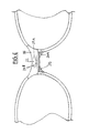
- the nose pad is made of three parts, it consists of a holding plate 22 with holes 23 for gripping grub screws for mounting on the glasses, a spacer 21 and a bracket 20 for resting on the bridge of the nose.
- a nose pad can be mounted either via a separate holding element 16 with grub screws 18 or directly via grub screws which protrude from the rear of the bridge and are mounted or recessed or injected therein.
- the functions of the bracket 20, the spacer element 21 and the holding plate 22 are taken over by a one-piece stainless steel molded part 10, the first end section 10A of which forms the bracket 20, the second end section 10B of which forms the holding plate 22 and whose tapered central section 10C acts as a spacer 21.
- This molded part 10 can be bent from a stamped part in accordance with the cross-sectional illustration of FIG. 5, so that, in adaptation to the shape and positioning of the bridge of the glasses, the planes of the two end sections 10A, 10B enclose an angle ⁇ of, for example, 60 ° to 70 °.
- the stainless steel molded part advantageously has a thickness of 0.4 to 0.8 mm.
- the bracket 20 or the end section 10A forming this bracket 20 is coated with a soft plastic material, for example silicone, and has openings 20B, 20C for better fixing of this plastic material (Shore A hardness of the silicone material in the range from 30 to 60 ).
- the bracket 20 is approximately in the form of a quarter circle, through the openings 20B, 20C in the lateral flank region of the bracket 20 a cross-sectional reduction is achieved, which allows the bracket to be easily bent or bent in the direction of the double arrows A, B (FIG. 3 ) and thus allows adaptation to the shape of the bridge of the nose. It is easy to see from the sectional view in FIG.
- the angle ⁇ between the plane of the two end sections 10A, 10B can be changed very simply by different bending at the transition regions X, Y between the middle section and the end sections and thus an adaptation of the nose pad plane to the bridge level of the glasses frame used.
- a suitable combination of the bending angles at the turning points X, Y a distance adjustment of the support surface relative to the plane of the holding plate can also be achieved to a certain extent. Both changes in distance and changes in the angle ⁇ , as well as changes in the shape of the bracket 20 are thus simple Bends and deformations possible, which can be done quickly and with great precision.
- FIG. 7 An assembly example is sketched using the example in FIG. 7: Two setscrews 26 are soldered onto the bridge 15 (corresponding threaded anchors are cast in with a plastic bridge), onto which the nose pad 10 can be pushed and secured with nuts 28. If the above-mentioned variation in the distance setting from the bridge 15 to the support area on the bridge of the nose is not sufficient, two spacer rings 27 can be inserted between the bridge 15 and the molded part 10, and this adjustment can also be supplemented in the simplest way.
Landscapes
- Physics & Mathematics (AREA)
- Health & Medical Sciences (AREA)
- General Physics & Mathematics (AREA)
- Ophthalmology & Optometry (AREA)
- Optics & Photonics (AREA)
- Eyeglasses (AREA)
Abstract
Description
- Die Erfindung betrifft eine Brille gemäß dem Oberbegriff des Patentanspruchs 1.
- Die ordnungsgemäße Positionierung eines Brillengestells ist von erheblicher Bedeutung, da hiervon einerseits der Strahlengang des einfallenden Lichtes und damit die beabsichtigte optische Wirkung bestimmt wird, andererseits aber eine anatomisch ungünstige oder ungeschickte Positionierung auch zu Beeinträchtigungen insbesondere Hautbeanspruchungen in den Auflagebereichen der Brille führen kann.
- Beide Problemkreise hängen naturgemäß zusammen und die eigentliche Problematik erwächst daraus, daß die hierfür relevanten anatomischen Gegebenheiten im Kopfbereich, also im Bereich der Nasenwurzel und der Nasenflügel und im Bereich der Ohren, bei jedem Menschen verschieden sind und auch bei Menschen unterschiedlicher Rasse voneinander abweichen.
- Beispielhaft seien hier nur genannt die Variationsbreite der Stirn um bis zu 10 mm, Formgebung und Breite der Nase, usw. Eine Zusammenstellung dieser für die Konzipierung eines Brillengestells relevanten anatomischen Gegebenheiten findet sich in NOJ 11/1990, Seite 8 bis 19.
- Um eine in optischer und anatomischer Hinsicht befriedigende Positionierung des Brillengestells an den individuellen Brillenträger zu ermöglichen, sind daher konstruktive Gestaltungen notwendig, die auf irgend-eine Weise so weit anpaßbar sind, daß die für den jeweiligen Brillenträger optimale Tragesituation zumindest in groben Zügen erreichbar ist. Diese Anpassung kann grundsätzlich auf zwei verschiedenen Art und Weisen erreicht werden, nämlich durch ein Bauteil, das in seiner Form in sich variabel ist, oder das in verschiedenen Größen und Abmessungen verfügbar ist. Es ist dann Aufgabe des Augenoptikers, an einer industriell gefertigten Brillenfassung mit handwerklichem Geschick solche Veränderungen vorzunehmen bzw. maßlich passende Bauteile auszuwählen, um die individuelle Anpassung an den Brillenträger zu ermöglichen. So werden beispielsweise von Herstellern Brillenfassungen in drei verschiedenen Brückenweiten (16 mm, 18 mm und 20 mm) angeboten, um zumindest eine Grobanpassung auf die Breite des Nasenrückens des Brillenträgers zu ermöglichen.
- In enger begrenzten Bereichen sind Anpassungen an die anatomischen Gegebenheiten des Brillenträgers auch durch eine weiche oder elastische Gestaltung erzielbar, wie dies beispielsweise durch die Verwendung von Silikon als Mantelungsmaterial bekannt ist, was zudem noch den Vorteil eines hohen Tragekomforts mit sich bringt.
- Aufgabe der Erfindung ist es, eine Nasenauflage so auszubilden, daß sie einfach montierbar und in einer einzigen Größe zuverlässig auf individuelle anatomische Gegebenheiten anpaßbar ist und zudem einen hohen Tragekomfort aufweist.
- Erfindungsgemäß wird diese Aufgabe durch den kennzeichnenden Teil des Patentanspruchs 1 gelöst.
- Der Grundgedanke der Erfindung besteht darin, daß mit der Auflage des Bügels ausschließlich auf dem Nasenrücken eine optimale Grundanpassung gewährleistet ist, da der Nasenrücken bei Europäern mit etwa 45° zur Hauptblickrichtung verläuft und somit mit engen Toleranzen weitgehend als konstant angesehen werden kann. Die Auswahl des Nasenrückens als Konstante zur Orientierung der Nasenauflage ist somit ein erster wichtiger Schritt zur Lösung der Aufgabe, da alle anderen, stärkeren Schwankungen unterworfenen Parameter, wie z.B. Nasenbreite und Gestaltung der Nasenflügel, von vornherein ausgeschlossen werden und eine individuelle Anpassung der Formgebung der Nasenauflage nur noch in engen Grenzen erfolgen muß und durch entsprechende Verformung der Nasenauflage selbst leicht erzielbar ist.
- Durch das Abstandselement wird darüber hinaus gewährleistet, daß die Brillenfassungen nicht zu dicht am Gesicht des Brillenträgers sitzen und auf Augenbrauen und Wangen aufliegen, so daß diese unerwünschten Hautkontakte und Verunreinigungen der Brille und der Gläser im Bereich der Augenbrauen durch Hautfette oder Hautschweiß zuverlässig vermieden werden.
- Weitere wesentliche Vorteile der Gestaltung der Nasenauflage nach der Erfindung bestehen in der äußerst kompakten und unauffälligen Montage am Brillengestell, so daß keinerlei ästhetische Beeinträchtigungen des Erscheinungsbildes der Brille auftreten können. An jeder Brille, ob Metallgestell oder Kunststoffgestell, können entsprechende Gewindezapfen angebracht oder eingelassen werden, die die Ausnehmungen der Halteplatte durchgreifen und über die die Nasenauflage leicht am Brillengestell befestigbar ist.
- Gemäß einer vorteilhaften Ausgestaltung der Brille nach dem Unteranspruch 2 ist vorgesehen, daß Bügel, Abstandselement und Halteplatte als einstückiges Formteil, insbesondere aus Edelstahl ausgebildet sind.
- Damit ergibt sich sowohl eine Verformungsmöglichkeit für den Bügel, als auch eine Einstellung des Abstandes und des Auflagewinkels durch entsprechende relative Positionierung bzw. Abbiegung des Mittelabschnittes gegenüber den beiden Endabschnitten, die den Bügel bzw. die Halteplatte bilden. Beispielsweise ist durch Verändern des Biegewinkels zwischen Halteplatte und Bügel eine leichte Anpassung an einen steileren Nasenrücken möglich, wie er beispielsweise bei Asiaten oft angetroffen wird.
- Gemäß einer weiteren Ausgestaltung ist vorgesehen, daß der Bügel Öffnungen zum Durchgriff des Materials einer Silikon-Ummantelung aufweist. Durch geeignete Dimensionierung dieser Öffnungen läßt sich der Materialquerschnitt des Bügels im Bereich beidseits der Öffnungen wählen, derart, daß eine Formung des kreisbogenähnlich vorgeformten Bügels leicht möglich ist, so daß auch eine eventuell noch notwendige Feinanpassung der Auflagefläche an die Nasenrückenform des Brillenträgers ohne Schwierigkeiten durchgeführt werden kann; damit ist insbesondere auch gewährleistet, daß die Nasenflügel von dem Gewicht der Brille entlastet werden, was insbesondere bei schweren Brillengestellen von Bedeutung ist, um Behinderungen und Beeinträchtigungen des Atmungsvorganges zu vermeiden.
- Darüber hinaus gestattet die bevorzugte Ausführungsform nach dem Patentanspruch 2 durch Verwendung eines einstückigen Formteils eine einfache Herstellung, da dieses Formteil als Stanzteil ausgebildet sein kann.
- Eine weitere bevorzugte Ausführungsform sieht vor, daß die Halteplatte mittels Stiften auf der Brücke befestigt ist, die beispielsweise als Gewindestifte auf der Metallbrücke aufgelötet sind, und daß zwischen Brücke und Halteplatte Distanzringe auf diese Stifte aufgeschoben sind.
- Hiermit ist eine weitere Variationsbreite bei der Einstellung des Abstandes der Brille vom Gesicht des Brillenträgers auf einfache Art und Weise erzielbar, die Distanzringe können hier beispielsweise aus Kunststoff sein, können aber auch aus Metall sein und/oder an die übrige Gestaltung des Brillengestells material- und farbmäßig angepaßt sein. Solche Distanzringe können beispielsweise 1 mm oder 2 mm dick sein.
- Weitere vorteilhafte Ausgestaltungen sind weiteren Unteransprüchen entnehmbar.
- Zwei Ausführungsbeispiele der erfindungsgemäßen Brille werden nun anhand von Zeichnungen näher erläutert, es zeigen:
- Figur 1:
- Eine perspektivische Prinzipdarstellung der ersten Ausführungsform der Nasenauflage,
- Figur 2:
- eine Darstellung der Nasenauflage gemäß Figur 1 in ihrer an einer Brille montierten Form,
- Figur 3:
- einen Längsschnitt in der Ebene C-D der Figur 4 durch ein zweites Ausführungsbeispiel der Nasenauflage,
- Figur 4:
- eine Aufsicht auf den Bügel der Nasenauflage,
- Figur 5:
- einen Querschnitt in der Ebene A-B durch die Nasenauflage der Figur 3 in der Ebene A-B,
- Figur 6:
- eine Vorderansicht einer Brille mit einer montierten Nasenauflage gemäß dem zweiten Ausführungsbeispiel nach den Figuren 3-5, und
- Figur 7:
- eine perspektivische Prinzipdarstellung der Montage einer Nasenauflage an einer Brille.
- Beim ersten Ausführungsbeispiel (Figur 1 und 2) ist die Nasenauflage dreiteilig ausgeführt, sie besteht aus einer Halteplatte 22 mit Bohrungen 23 zum Durchgriff von Gewindestiften zur Montage an der Brille, einem Abstandselement 21 und einem Bügel 20 zur Auflage auf dem Nasenrücken. Eine solche Nasenauflage kann entweder über ein separates Halteelement 16 mit Gewindestiften 18 oder auch direkt über Gewindestifte montiert werden, die auf der Rückseite der Brücke hervorragen und in dieser montiert bzw. eingelassen oder eingespritzt sind.
- Beim zweiten Ausführungsbeispiel (Figuren 3 bis 7) werden die Funktionen des Bügels 20, des Abstandselementes 21 und der Halteplatte 22 von einem einstückigen Edelstahl-Formteil 10 übernommen, dessen erster Endabschnitt 10A den Bügel 20 bildet, dessen zweiter Endabschnitt 10B die Halteplatte 22 bildet und dessen verjüngter Mittelabschnitt 10C als Abstandselement 21 wirkt. Dieses Formteil 10 kann aus einem Stanzteil entsprechend der Querschnittsdarstellung der Figur 5 abgebogen werden, so daß in Anpassung an die Form und Positionierung der Brücke der Brille die Ebenen der beiden Endabschnitte 10A,10B einen Winkel α von beispielsweise 60° bis 70° einschließen. Vorteilhafterweise weist das Edelstahl-Formteil eine Dicke von 0,4 bis 0,8 mm auf.
Der Bügel 20 bzw. der diesen Bügel 20 bildende Endabschnitt 10A ist mit einem weichen Kunststoffmaterial, beispielsweise Silikon, ummantelt und weist zur besseren Fixierung dieses Kunststoffmaterials Öffnungen 20B,20C auf (Shore-A-Härte des Silicon-Materials im Bereich von 30 bis 60).
Der Bügel 20 ist beim dargestellten Ausführungsbeispiel etwa in Form eines Viertelkreises ausgebildet, durch die Öffnungen 20B,20C wird im seitlichen Flankenbereich des Bügels 20 eine Querschnittsreduzierung bewirkt, die ein leichtes Auf- oder Zubiegen des Bügels in Richtung der Doppelpfeile A,B (Figur 3) und somit eine Anpassung an die Nasenrückenform ermöglicht.
Aus der Schnittdarstellung der Figur 5 ist leicht zu entnehmen, daß der Winkel α zwischen der Ebene der beiden Endabschnitte 10A,10B sehr einfach durch unterschiedliche Abbiegung an den Übergangsbereichen X,Y zwischen Mittelabschnitt und Endabschnitte geändert werden kann und somit eine Anpassung der Nasenauflage-Ebene an die Brückenebene des jeweils eingesetzten Brillengestells. Durch geeignete Kombination der Abbiegewinkel an den Abbiegestellen X,Y läßt sich auch in bestimmtem Maße eine Abstandseinstellung der Auflagefläche relativ zur Ebene der Halteplatte erzielen. Sowohl Abstandsänderungen als auch Änderungen des Winkels α , als auch Änderungen der Formgebung des Bügels 20 sind somit durch einfache Abbiegungen und Verformungsvorgänge möglich, die schnell und mit großer Präzision vorgenommen werden können. - Am Beispiel der Figur 7 ist schließlich noch ein Montagebeispiel skizziert:
Auf der Brücke 15 sind zwei Gewindestifte 26 aufgelötet (bei einer Kunststoffbrücke sind entsprechende Gewindeanker eingegossen), auf die die Nasenauflage 10 aufschiebbar und mit Muttern 28 sicherbar ist. Sollte die oben angesprochene Variationsbreite der Abstandseinstellung von der Brücke 15 zum Auflagebereich auf dem Nasenrücken nicht ausreichen, so können zwei Distanzringe 27 zwischen Brücke 15 und Formteil 10 eingelegt werden, auch diese Anpassung kann auf einfachste Weise somit ergänzt werden.
Claims (14)
- Brille mit einer die Ränder der Gläser verbindenden Brücke und einer auf der dem Brillenträger zugewandten Seite der Brücke montierbaren Nasenauflage,
dadurch gekennzeichnet, daß die Nasenauflage einen einteiligen Bügel (20) beinhaltet, der über ein Abstandselement (21) an einer Ausnehmungen (23) aufweisenden Halteplatte (22) gehalten ist, und daß der Bügel (20) kreisbogenähnlich geformt ist, derart, daß er im wesentlichen nur auf dem Nasenrücken aufliegt. - Brille nach Anspruch 1, dadurch gekennzeichnet, daß Bügel (20), Abstandselement (21) und Halteplatte (22) jeweils als Abschnitt eines einstückigen Formteils (10) ausgebildet sind, dessen erster Endabschnitt (10A) den Bügel (20) und dessen zweiter Endabschnitt (10B) die Halteplatte (22) bildet, die miteinander über einen Mittelabschnitt (10C) verbunden sind, der das Abstandselement (21) bildet.
- Brille nach Anspruch 1 oder 2, dadurch gekennzeichnet, daß der Bügel (20) eine weiche Ummantelung (20A) aus Kunststoff aufweist.
- Brille nach Anspruch 2, dadurch gekennzeichnet, daß die Ebenen der beiden Endbereiche (10A,10B) des Formteils (10) einen Winkel (α) von etwa 60° bis 90° miteinander einschließen.
- Brille nach Anspruch 2, dadurch gekennzeichnet, daß das Formteil (10) aus Edelstahl ist und eine Dicke von 0,4-0,8 mm aufweist.
- Brille nach Anspruch 1 oder 2, dadurch gekennzeichnet, daß der Bügel (20) Öffnungen (20B,20C) zum Durchgriff des Materials der Ummantelung (20A) aufweist.
- Brille nach Anspruch 1, dadurch gekennzeichnet, daß die Länge des Abstandselementes (10C) mindestens 3 mm beträgt.
- Brille nach Anspruch 4, dadurch gekennzeichnet, daß der Winkel (α) durch je eine Abbiegung (X,Y) des Abstandselementes (10C) im Übergangsbereich zum jeweiligen Endabschnitt (10A,10B) gebildet ist.
- Brille nach Anspruch 1 oder 2, dadurch gekennzeichnet, daß die Halteplatte (22) zwei Bohrungen (23,23A,23B) aufweist, und daß die Brücke (15) Stifte (18,26) mit Außengewinde aufweist, die die Bohrungen der Halteplatte (22) durchgreifen, und daß Gewindemuttern (28) die Halteplatte (22) an der Brücke (15) sichern.
- Brille nach Anspruch 9, dadurch gekennzeichnet, daß zwischen Brücke (15) und Halteplatte (10) Distanzringe auf die Stifte (26) aufgeschoben sind.
- Brille nach Anspruch 9, dadurch gekennzeichnet, daß die Stifte (18) auf einer separaten Halterung (16) aufgebracht sind, die auf der Brücke (15) befestigt ist.
- Brille nach Anspruch 9, dadurch gekennzeichnet, daß die Stifte (26) unmittelbar auf der Brücke (15) aufgebracht sind.
- Brille nach Anspruch 12, dadurch gekennzeichnet, daß die Stifte (26) Gewindestifte sind, die auf einer Metallbrücke aufgelötet sind.
- Brille nach Anspruch 12, dadurch gekennzeichnet, daß die Stifte (26) Gewindeanker sind, die in die Kunststoffbrücke eingelassen sind.
Applications Claiming Priority (2)
| Application Number | Priority Date | Filing Date | Title |
|---|---|---|---|
| DE9004468U DE9004468U1 (de) | 1990-04-19 | 1990-04-19 | Brille |
| DE9004468U | 1990-04-19 |
Publications (3)
| Publication Number | Publication Date |
|---|---|
| EP0452709A2 true EP0452709A2 (de) | 1991-10-23 |
| EP0452709A3 EP0452709A3 (en) | 1992-04-15 |
| EP0452709B1 EP0452709B1 (de) | 1995-09-27 |
Family
ID=6853039
Family Applications (1)
| Application Number | Title | Priority Date | Filing Date |
|---|---|---|---|
| EP91104694A Expired - Lifetime EP0452709B1 (de) | 1990-04-19 | 1991-03-26 | Brille mit Nasenauflage |
Country Status (8)
| Country | Link |
|---|---|
| US (2) | US5200771A (de) |
| EP (1) | EP0452709B1 (de) |
| JP (1) | JPH04230731A (de) |
| KR (1) | KR0156941B1 (de) |
| AT (1) | ATE128560T1 (de) |
| DE (2) | DE9004468U1 (de) |
| ES (1) | ES2078985T3 (de) |
| HK (1) | HK95396A (de) |
Families Citing this family (17)
| Publication number | Priority date | Publication date | Assignee | Title |
|---|---|---|---|---|
| DE9004468U1 (de) * | 1990-04-19 | 1990-06-28 | Schmolz, Ingeborg, 8000 München | Brille |
| USD367666S (en) | 1994-10-28 | 1996-03-05 | Bausch & Lomb Incorporated | Eyewear lens front |
| US5771087A (en) * | 1996-10-16 | 1998-06-23 | Sentinel Importing Corporation | Eyewear and nosepad for use with eyewear |
| US6010215A (en) * | 1999-03-23 | 2000-01-04 | Miceli; Sylvana | Makeup eyeglasses |
| US6601955B1 (en) | 2001-07-17 | 2003-08-05 | Wis Sarl | Nose pad assembly |
| AU2002258177A1 (en) * | 2002-04-17 | 2003-10-27 | Safilo Societa Azionaria Fabbrica Italiana Lavorazione Occhiali S.P.A. | Spectacles with western/eastern variation of fit |
| US20040080706A1 (en) * | 2002-10-24 | 2004-04-29 | Newton Howard | Eyewear for lazy eyes or dyslexia |
| US9110311B2 (en) * | 2012-09-04 | 2015-08-18 | Hock Wah Yeo | Eyewear nose support for low bridge nose |
| US10485283B2 (en) | 2015-09-04 | 2019-11-26 | Brian Dennis Jenkins | Safety glasses deployment system |
| US10031345B2 (en) | 2015-12-15 | 2018-07-24 | LooLoops, LLC | Slip-resistant eyewear system |
| US10444534B2 (en) | 2016-09-12 | 2019-10-15 | LooLoopsLLC | Slip-resistant eyewear system |
| WO2017106385A2 (en) | 2015-12-15 | 2017-06-22 | LooLoops, LLC | Slip-resistant eyewear system |
| US20180239165A1 (en) * | 2017-02-21 | 2018-08-23 | General Scientific Corp. | Custom fit nose pads for spectacle frames |
| US11402658B2 (en) * | 2019-07-30 | 2022-08-02 | General Scientific Corp. / Surgitel | Removable, adjustable wire arms for nose pads |
| US12353061B2 (en) | 2020-10-09 | 2025-07-08 | 3M Innovative Properties Company | Universal-fit eyeglasses |
| FR3115892A1 (fr) * | 2020-11-03 | 2022-05-06 | Ny Lova RAFALIMANANA | Support de monture de lunettes de vue. |
| KR102565302B1 (ko) * | 2021-02-25 | 2023-08-09 | 류정민 | 긴밀성과 안착력이 뛰어난 안경테용 코받침 |
Family Cites Families (23)
| Publication number | Priority date | Publication date | Assignee | Title |
|---|---|---|---|---|
| DE280566C (de) * | ||||
| US1789937A (en) * | 1930-03-03 | 1931-01-20 | Shur On Optical Company Inc | Ophthalmic mounting |
| US2596572A (en) * | 1949-09-29 | 1952-05-13 | Welsh Mfg Co | Two-color spectacle bridge |
| FR1049849A (fr) * | 1952-01-24 | 1954-01-04 | Harry Vargon Fils De | Perfectionnements aux montures de lunettes |
| GB750551A (en) * | 1954-04-29 | 1956-06-20 | Maurice Garson | Improvements in or relating to spectacles |
| DE1683390U (de) * | 1954-07-07 | 1954-09-16 | August Wulf Celluloid Und Meta | Brillengestell aus zelluloid, kunststoff od. dgl., insbesondere fuer sonnenbrillen. |
| FR1112947A (fr) * | 1954-10-21 | 1956-03-20 | Plaquette de lunette | |
| FR1115206A (fr) * | 1954-11-29 | 1956-04-20 | Gabriel Tabourin Ets | Perfectionnements à la fabrication des montures de lunettes |
| FR1432641A (fr) * | 1965-02-08 | 1966-03-25 | Lunettes | |
| FR1540371A (fr) * | 1967-04-18 | 1968-09-27 | Plaquettes nasales réglables pour lunettes | |
| US3556959A (en) * | 1968-03-29 | 1971-01-19 | Frank Passal | Nickel plating |
| FR2151656A5 (de) * | 1971-09-08 | 1973-04-20 | Silor | |
| FR2157155A6 (de) * | 1971-10-20 | 1973-06-01 | Silor Sa | |
| FR2164074A5 (de) * | 1971-12-07 | 1973-07-27 | Berthet Bondet Abel | |
| US3758203A (en) * | 1972-01-27 | 1973-09-11 | Halco Ind Inc | Eyeglasses frame construction |
| US4190333A (en) * | 1978-01-16 | 1980-02-26 | Lambert Anodizing Co. Inc. | Spectacle frames |
| FR2428857A1 (fr) * | 1978-06-14 | 1980-01-11 | Lacoste Chemise | Monture de lunettes |
| DE3506073A1 (de) * | 1985-02-21 | 1986-08-21 | Simro AG, Meilen | Seiten- und sattelstegpartie fuer eine brille |
| GB8704656D0 (en) * | 1987-02-27 | 1987-04-01 | Chappell N W | Spectacle frame |
| US4787729A (en) * | 1987-08-24 | 1988-11-29 | Ruffen Kenneth T | Eyeglass nose support |
| FR2628222B1 (fr) * | 1988-03-01 | 1991-10-04 | Hennert | Dispositif de reglage pour monture de lunettes |
| DE8804232U1 (de) * | 1988-03-29 | 1988-06-23 | Fritsche-Fingerhut, Elke, 6242 Kronberg | Veränderbare Brille |
| DE9004468U1 (de) * | 1990-04-19 | 1990-06-28 | Schmolz, Ingeborg, 8000 München | Brille |
-
1990
- 1990-04-19 DE DE9004468U patent/DE9004468U1/de not_active Expired - Lifetime
-
1991
- 1991-03-26 DE DE59106566T patent/DE59106566D1/de not_active Expired - Fee Related
- 1991-03-26 EP EP91104694A patent/EP0452709B1/de not_active Expired - Lifetime
- 1991-03-26 ES ES91104694T patent/ES2078985T3/es not_active Expired - Lifetime
- 1991-03-26 AT AT91104694T patent/ATE128560T1/de not_active IP Right Cessation
- 1991-04-04 KR KR1019910005456A patent/KR0156941B1/ko not_active Expired - Fee Related
- 1991-04-10 JP JP3164047A patent/JPH04230731A/ja active Pending
- 1991-04-19 US US07/687,485 patent/US5200771A/en not_active Ceased
-
1994
- 1994-09-29 US US08/315,140 patent/USRE36048E/en not_active Expired - Lifetime
-
1996
- 1996-05-30 HK HK95396A patent/HK95396A/xx not_active IP Right Cessation
Also Published As
| Publication number | Publication date |
|---|---|
| EP0452709B1 (de) | 1995-09-27 |
| US5200771A (en) | 1993-04-06 |
| USRE36048E (en) | 1999-01-19 |
| DE59106566D1 (de) | 1995-11-02 |
| KR910018828A (ko) | 1991-11-30 |
| ATE128560T1 (de) | 1995-10-15 |
| HK95396A (en) | 1996-06-07 |
| JPH04230731A (ja) | 1992-08-19 |
| ES2078985T3 (es) | 1996-01-01 |
| KR0156941B1 (ko) | 1999-05-01 |
| DE9004468U1 (de) | 1990-06-28 |
| EP0452709A3 (en) | 1992-04-15 |
Similar Documents
| Publication | Publication Date | Title |
|---|---|---|
| EP0452709B1 (de) | Brille mit Nasenauflage | |
| DE60104565T2 (de) | Randlose brille mit linsenhalterungsstabilität | |
| DE69902915T2 (de) | Aufklemmbare abschirmung für brillen und eine kombination einer entfernbaren abschirmung mit einer brille | |
| DE3785512T2 (de) | Linsenhalterung fuer brillen, insbesondere fuer rahmenlose brillen. | |
| EP0081179A1 (de) | Randlose Brille | |
| DE69803214T2 (de) | Ein brillengestell, eine brille und verfahren zur herstellung einer brille | |
| DE69918307T2 (de) | Modulare lesebrille | |
| DE69636071T2 (de) | Schutzvorrichtung mit klemmbefestigung für brillen | |
| DE60018214T2 (de) | Vorrichtung zur befestigung zusätzlicher linsen auf brillen | |
| DE3325425A1 (de) | Verstellbares brillengestell | |
| DE3032485A1 (de) | Verfahren und vorrichtung zum einstellen und halten von brillenglaesern | |
| DE69324498T2 (de) | Semi-randlose brillenfassung | |
| EP0167551B1 (de) | Weicher brillen-sattelsteg | |
| EP0100392B1 (de) | Stufenlos längenverstellbarer Brillenbügel | |
| DE1227691B (de) | Brillenfassung mit Metallbuegel | |
| DE3148166C1 (de) | Randlose Brille | |
| DE2825711A1 (de) | Federscharnier fuer brillen | |
| DE8519305U1 (de) | Skibrille mit optischem Einsatz | |
| DE102015011955B4 (de) | Brille und Verfahren zur Herstellung einer solchen Brille | |
| EP0386019A1 (de) | Brille mit auswechselbaren gläsern | |
| DE3137173A1 (de) | Brille | |
| DE2825712A1 (de) | Brillenbuegel | |
| DE3716525A1 (de) | Walkman-kopfhoerer | |
| DE102008020917A1 (de) | Vorrichtung zum Halten einer Brille | |
| DE9309509U1 (de) | Brille |
Legal Events
| Date | Code | Title | Description |
|---|---|---|---|
| PUAI | Public reference made under article 153(3) epc to a published international application that has entered the european phase |
Free format text: ORIGINAL CODE: 0009012 |
|
| AK | Designated contracting states |
Kind code of ref document: A2 Designated state(s): AT DE ES FR GB IT |
|
| PUAL | Search report despatched |
Free format text: ORIGINAL CODE: 0009013 |
|
| AK | Designated contracting states |
Kind code of ref document: A3 Designated state(s): AT DE ES FR GB IT |
|
| 17P | Request for examination filed |
Effective date: 19920930 |
|
| 17Q | First examination report despatched |
Effective date: 19940323 |
|
| RAP1 | Party data changed (applicant data changed or rights of an application transferred) |
Owner name: F+W FREY & WINKLER GMBH |
|
| GRAA | (expected) grant |
Free format text: ORIGINAL CODE: 0009210 |
|
| AK | Designated contracting states |
Kind code of ref document: B1 Designated state(s): AT DE ES FR GB IT |
|
| REF | Corresponds to: |
Ref document number: 128560 Country of ref document: AT Date of ref document: 19951015 Kind code of ref document: T |
|
| REF | Corresponds to: |
Ref document number: 59106566 Country of ref document: DE Date of ref document: 19951102 |
|
| ITF | It: translation for a ep patent filed | ||
| REG | Reference to a national code |
Ref country code: ES Ref legal event code: FG2A Ref document number: 2078985 Country of ref document: ES Kind code of ref document: T3 |
|
| GBT | Gb: translation of ep patent filed (gb section 77(6)(a)/1977) |
Effective date: 19951229 |
|
| ET | Fr: translation filed | ||
| PLBE | No opposition filed within time limit |
Free format text: ORIGINAL CODE: 0009261 |
|
| STAA | Information on the status of an ep patent application or granted ep patent |
Free format text: STATUS: NO OPPOSITION FILED WITHIN TIME LIMIT |
|
| 26N | No opposition filed | ||
| REG | Reference to a national code |
Ref country code: GB Ref legal event code: IF02 |
|
| PGFP | Annual fee paid to national office [announced via postgrant information from national office to epo] |
Ref country code: GB Payment date: 20020305 Year of fee payment: 12 |
|
| PGFP | Annual fee paid to national office [announced via postgrant information from national office to epo] |
Ref country code: AT Payment date: 20020322 Year of fee payment: 12 |
|
| PGFP | Annual fee paid to national office [announced via postgrant information from national office to epo] |
Ref country code: ES Payment date: 20020325 Year of fee payment: 12 |
|
| PGFP | Annual fee paid to national office [announced via postgrant information from national office to epo] |
Ref country code: DE Payment date: 20021115 Year of fee payment: 13 |
|
| PGFP | Annual fee paid to national office [announced via postgrant information from national office to epo] |
Ref country code: FR Payment date: 20030318 Year of fee payment: 13 |
|
| PG25 | Lapsed in a contracting state [announced via postgrant information from national office to epo] |
Ref country code: GB Free format text: LAPSE BECAUSE OF NON-PAYMENT OF DUE FEES Effective date: 20030326 Ref country code: AT Free format text: LAPSE BECAUSE OF NON-PAYMENT OF DUE FEES Effective date: 20030326 |
|
| PG25 | Lapsed in a contracting state [announced via postgrant information from national office to epo] |
Ref country code: ES Free format text: LAPSE BECAUSE OF NON-PAYMENT OF DUE FEES Effective date: 20030327 |
|
| GBPC | Gb: european patent ceased through non-payment of renewal fee |
Effective date: 20030326 |
|
| REG | Reference to a national code |
Ref country code: ES Ref legal event code: FD2A Effective date: 20030327 |
|
| PG25 | Lapsed in a contracting state [announced via postgrant information from national office to epo] |
Ref country code: DE Free format text: LAPSE BECAUSE OF NON-PAYMENT OF DUE FEES Effective date: 20041001 |
|
| PG25 | Lapsed in a contracting state [announced via postgrant information from national office to epo] |
Ref country code: FR Free format text: LAPSE BECAUSE OF NON-PAYMENT OF DUE FEES Effective date: 20041130 |
|
| REG | Reference to a national code |
Ref country code: FR Ref legal event code: ST |
|
| PG25 | Lapsed in a contracting state [announced via postgrant information from national office to epo] |
Ref country code: IT Free format text: LAPSE BECAUSE OF NON-PAYMENT OF DUE FEES;WARNING: LAPSES OF ITALIAN PATENTS WITH EFFECTIVE DATE BEFORE 2007 MAY HAVE OCCURRED AT ANY TIME BEFORE 2007. THE CORRECT EFFECTIVE DATE MAY BE DIFFERENT FROM THE ONE RECORDED. Effective date: 20050326 |