EP0441801B1 - Dispositif permettant de revetir des cables electriques de douilles moulees ou de gaines de protection antiflexion - Google Patents
Dispositif permettant de revetir des cables electriques de douilles moulees ou de gaines de protection antiflexion Download PDFInfo
- Publication number
- EP0441801B1 EP0441801B1 EP89911361A EP89911361A EP0441801B1 EP 0441801 B1 EP0441801 B1 EP 0441801B1 EP 89911361 A EP89911361 A EP 89911361A EP 89911361 A EP89911361 A EP 89911361A EP 0441801 B1 EP0441801 B1 EP 0441801B1
- Authority
- EP
- European Patent Office
- Prior art keywords
- elongated body
- annular body
- annular
- rod
- diameter
- Prior art date
- Legal status (The legal status is an assumption and is not a legal conclusion. Google has not performed a legal analysis and makes no representation as to the accuracy of the status listed.)
- Expired - Lifetime
Links
Images
Classifications
-
- H—ELECTRICITY
- H01—ELECTRIC ELEMENTS
- H01R—ELECTRICALLY-CONDUCTIVE CONNECTIONS; STRUCTURAL ASSOCIATIONS OF A PLURALITY OF MUTUALLY-INSULATED ELECTRICAL CONNECTING ELEMENTS; COUPLING DEVICES; CURRENT COLLECTORS
- H01R43/00—Apparatus or processes specially adapted for manufacturing, assembling, maintaining, or repairing of line connectors or current collectors or for joining electric conductors
- H01R43/005—Apparatus or processes specially adapted for manufacturing, assembling, maintaining, or repairing of line connectors or current collectors or for joining electric conductors for making dustproof, splashproof, drip-proof, waterproof, or flameproof connection, coupling, or casing
-
- H—ELECTRICITY
- H02—GENERATION; CONVERSION OR DISTRIBUTION OF ELECTRIC POWER
- H02G—INSTALLATION OF ELECTRIC CABLES OR LINES, OR OF COMBINED OPTICAL AND ELECTRIC CABLES OR LINES
- H02G1/00—Methods or apparatus specially adapted for installing, maintaining, repairing or dismantling electric cables or lines
- H02G1/14—Methods or apparatus specially adapted for installing, maintaining, repairing or dismantling electric cables or lines for joining or terminating cables
Definitions
- the invention relates to a device for pulling kink protection or molded sleeves onto electrical cables.
- grommets are required in connection with the electrical power supply in practically all electrical devices or electrical devices; the grommet represents a stiffening of a cable at a certain point and thus prevents the cable from kinking at this point and being damaged as a result.
- Such grommets are both on cables for high-voltage as well as for low-current devices such. B. available on telephone devices.
- the grommets must be tight and immovable at the predetermined location on the electrical cables. They consist of a rubber mixture, their central bore being adapted to the outside diameter of the electrical cable in question so that the grommet sits immovably on the cable in the pulled-up state.
- the invention also applies to all types of grommets or rubber grommets, that is to say also for hose grommets, cable lug grommets, strain relief grommets and, in general, for cable or other bushings as well as for rubber or other caps.
- Grommets are pulled onto electrical cables with the help of so-called three-prong pliers.
- the three mandrels of such pliers are attached to the two jaws in a mutually parallel orientation. By pressing the pliers handles together, the mandrels can be moved away from each other while maintaining their parallel position.
- the pliers handles pull the three mandrels and thus the spout bore apart in the radial direction so that the electrical cable can be pushed through the now enlarged inner bore of the spout. Then the pliers handles are released.
- the grommet contracts again in the radial direction, the mandrels being pressed in between the grommet and the cable. Pulling out the mandrels from the inside of the grommet requires some effort. A much greater effort is required when spreading the mandrels, ie when spreading the spout. The opening of spouts is therefore one of the tasks that can only be carried out at short notice and not over a longer period of time.
- the invention has for its object to provide a way that allows you to pull grommets on electrical cables without much effort.
- the device for pulling on kink protection or molded sleeves on electrical cables it is characterized by an elongated body, one end region of which is designed as a bushing and the other end region of which is designed as a rod and in which the longitudinal axis of the bushing and the longitudinal axis of the rod coincide, wherein the outside diameter of this rod is slightly smaller than the inside diameter of the longitudinal bushing and the inside diameter of the longitudinal bore in the bushing is slightly larger than the outside diameter of the cable and the outside diameter of the bushing is larger than the outside diameter of the rod, the surfaces of the two end regions gradually merge from rifle and rod.
- this device is characterized by an annular body, the central bore in the Diameter is only slightly larger than the respective diameter of the elongated body along its longitudinal axis, the elongated body and the annular body being movable relative to one another in the direction of the longitudinal axis of the elongated body such that the annular body can be pushed completely over the elongated body .
- the displacement relative to the elongated body takes place with the help of the annular body, on which the spout can be supported in the longitudinal direction. By moving the annular body in the longitudinal direction of the rod-shaped body, the spout also shifts.
- a wide variety of technical devices can be used for the relative movement of the annular body and the rod-shaped body.
- a further development of the invention which is particularly advantageous for handling the device according to the invention is characterized in that tension-compression members are present, to which the elongated body and the annular body can be coupled in such a way that either the elongated body passes through the annular body. or the annular body can be slid over the elongated body.
- the elongated body can be releasably attached to at least one tension member and the annular body can be pressed against the spout so that the spout can be pushed over the elongated body.
- the effort required for the relative movement of the elongated body or grommet and the annular body can advantageously be kept to a minimum by a pneumatic actuation of the tension-compression members.
- an undercut is present in the one end region of the elongated body, into which the at least one tension member can be releasably engaged.
- the annular body Since the annular body presses against the spout during the entire displacement of the spout, the annular body must also expand as the spout widens. This widening of the annular body can be accomplished with simple aids in that there are at least one, preferably several, longitudinally extending slots in the wall of the annular body, which extend at least partially through the body wall in the longitudinal direction.
- the pull members projecting in the longitudinal direction are thus resiliently mounted in the radial direction to the longitudinal axis.
- the annular body is advantageously surrounded by an elastic tension member which surrounds at least in some areas. This tension member can be implemented in a technically simple manner by means of a helical spring.
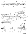
- the cable sheath 14 is present in its right end region 12 in the drawing.
- a spout 16 is pushed onto the jacket region 14 adjoining the end region 12.
- the diameter D2 of the longitudinal bore 18 extending through the grommet 16 is adapted to the outer diameter D1 of the cable 10, so that the grommet 16 sits tightly on the electrical cable 10 in the pulled-up state - as shown in FIG. 1.
- the individual strands 20 of the electrical cable 10 are exposed in the end region 12.
- a fitting 22 belongs to the device according to the invention.
- This fitting 22 has the shape of an elongated body.
- the shaped piece 22 In its one end area - on the left in FIG. 2 - the shaped piece 22 has a sleeve-like shape 23 with an outer diameter D4.
- the inner bore 24 of the fitting 22 has the diameter D3.
- the - in FIG. 2 left - open end of the shaped piece 22 has a conical bevel 26.
- the bore 24 is inside the shaped piece 22 closed by an end face 30. In the area between the conical bevel 26 and the end face 30, the shaped piece 22 thus has the shape of a sleeve 23.
- the other - in Fig. 2 right - end of the shaped piece 22 has a circular cylindrical, rod-shaped shape 32 with the outer diameter D5.
- the transition from the cylindrical surface shape with the diameter D4 to the cylindrical surface area with the diameter D5 takes place gradually in a conically tapering surface area 34 - from left to right in FIG. 2.
- the right free end of the rod-shaped area 32 of the shaped piece 22 is provided with a tip 36.
- An annular groove 38 is formed in the rod 32 behind the tip.
- the diameter D5 of the rod 32 is accordingly somewhat smaller than the inner diameter D2 of the longitudinal bore 18 of the spout 16.
- the cable 10 with its exposed strands 20 can be inserted into the bore 24 of the fitting 22 from direction 42. This insertion movement is facilitated by the conical bevel 26 of the fitting 22.
- the cable can be inserted into the bore 24 until its strands come to rest on the end face 30 of the bore 24.
- the diameter D3 of the bore 24 is slightly larger than the outer diameter D1 of the electrical cable 10, so that this insertion movement can take place without great effort.
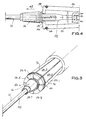
- the longitudinal axis 52 of the fitting 22 surrounding thrust arms 54 of a tension-compression device are used, which can be pressed with correspondingly designed contact surfaces 56 to the - in the drawing right - face 59 of the spout 16 ( 3, 4 and 5).
- the push arms 54 have a front bend 58 which leaves a distance D6 between them.
- the distance D6 corresponds to the diameter of a circle.
- D6 is slightly larger than the diameter D5 of the rod 32, so that the shaped piece 22 with its rod 32 can be pushed through the region D6 — to the right in FIG. 3.
- the bends 58 of the push arms 54 come to rest on the end face 59 of the spout 16, and with a corresponding further pushing movement of the push arms 54 the spout 16 becomes in the direction 62, moved into the area with the diameter D4 of the shaped piece 22.
- the spout 16 with its longitudinal bore 18 widens further than it corresponds to the dimension D1 of the electrical cable 10.
- the shaped piece 22 is then decoupled from the gripping arms 60, which can be done, for example, by slightly moving the gripping arms 60 transversely to the longitudinal axis 52. After the push arms 54 have been moved back into the position shown in FIG. 3, a new grommet 16 can be pushed onto the fitting 22 and then pushed onto a corresponding new cable 10.
- the thrust arms 54 are present in several and are separated from one another by gaps 70 parallel to the longitudinal axis 52.
- the individual push arms 54.1, 54.2, 54.3, 54.4, 54.5, 54.6, 54.7, 54.8 are thus designed in the form of cantilever arms, the respective bend 58 of each push arm 54 representing the projecting free end thereof (FIG. 5).
- the push arms 54 can be moved by means of corresponding lever ratios without great effort. A particularly effortless shifting takes place with the help of pneumatically actuated two-way cylinders; Compressed air is regularly available in commercial companies.
- the coupling of the shaped piece 22 to the gripping arms 60 need not take place in the manner shown.
- the coupling can also be accomplished, for example, by means of a bayonet-type closure, which can be engaged or disengaged by rotating it about the longitudinal axis 52 of the molded piece 22.
- the gripping arms 60 can also be moved relative to the push arms 54. What is important is only a relative movement between the shaped piece 22 and the contact surface 56.
- the sliding movement of the spout 16 along the fitting 22 can be done by applying lubricants such.
- lubricants such as B. Vaseline or talcum powder can be facilitated.
Landscapes
- Engineering & Computer Science (AREA)
- Manufacturing & Machinery (AREA)
- Insulating Bodies (AREA)
- Installation Of Indoor Wiring (AREA)
Abstract
Claims (8)
- Dispositif de montage de douilles moulées ou de protection contre le pliage (16) sur des câbles électriques (10),
caractérisé par- un corps allongé (22)- dont une partie d'extrémité présente la forme d'une douille (23) et- dont l'autre part d'extrémité présente la forme d'un barreau (32),- dans lequel l'axe longitudinal (52) de la douille (23) et l'axe longitudinal (52) du barreau (32) coïncident,- dans lequel le diamètre extérieur (D5) du barreau (32) est légèrement plus petit que le diamètre intérieur (D2) de l'alésage longitudinal traversant la douille (19),- dans lequel le diamètre intérieur (D3) de l'alésage longitudinal (24) de la douille (23) est légèrement plus grand que le diamètre extérieur (D1) du câble (10),- dans lequel le diamètre extérieur (D4) de la douille (23) est supérieur au diamètre extérieur (D5) du barreau (32),- dans lequel les surfaces des deux parties d'extrémité se raccordent progressivement (34) l'une à l'autre,ainsi que par- un corps annulaire (58),- dont le diamètre (D6) de l'alésage axial n'est que légèrement plus grand que le diamètre (D4, D5) que présente le corps allongé (22) le long de son axe longitudinal (52),- le corps allongé (22) et le corps annulaire (58) pouvant être déplacés l'un par rapport à l'autre suivant la direction de l'axe longitudinal (52) de sorte que le corps annulaire (58) puisse glisser complètement sur le corps allongé (22). - Dispositif selon la revendication 1, caractérisé en ce qu'il existe des éléments de traction et de poussée (54, 60) auxquels le corps allongé (22) et le corps annulaire (58) peuvent être accouplés de telle sorte que le corps annulaire (58) puisse être glissé le long du corps allongé (22) ou que le corps annulaire (58) puisse être glissé sur le corps allongé (22).
- Dispositif selon la revendication 2, caractérisé en ce que le corps allongé (22) est fixé de manière amovible à au moins un élément de traction (60) et en ce que le corps annulaire (58) puisse être écarté par glissement du corps allongé (22) par au moins un élément de poussée (54).
- Dispositif selon la revendication 3, caractérisé en ce que dans une des parties d'extrémité du corps allongé (22) il existe une contre-dépouille (38) au moins partiellement annulaire dans laquelle le ou les éléments de traction (60) peuvent s'accrocher de manière amovible.
- Dispositif selon la revendication 2, caractérisé en ce que les éléments de traction et de poussée (54, 60) peuvent être actionnés pneumatiquement.
- Dispositif selon la revendication 1, caractérisé en ce que dans la paroi du corps annulaire (58) existe au moins une fente (70) s'étendant dans la direction longitudinale du corps annulaire (58) et traversant au moins partiellement la paroi du corps annulaire (58) dans le sens de la longueur de celui-ci.
- Dispositif selon la revendication 6, caractérisé en ce que le corps annulaire (58) est entouré par un élément de traction (64) élastique qui l'entoure au moins partiellement en forme d'anneau.
- Dispositif selon la revendication 7, caractérisé en ce que l'élément de traction est un ressort hélicoïdal (64).
Priority Applications (1)
| Application Number | Priority Date | Filing Date | Title |
|---|---|---|---|
| AT89911361T ATE93997T1 (de) | 1988-11-08 | 1989-10-17 | Vorrichtung zum aufziehen von knickschutz- oder formtuellen auf elektrische kabel. |
Applications Claiming Priority (2)
| Application Number | Priority Date | Filing Date | Title |
|---|---|---|---|
| DE8813932U | 1988-11-08 | ||
| DE8813932U DE8813932U1 (fr) | 1988-11-08 | 1988-11-08 |
Publications (2)
| Publication Number | Publication Date |
|---|---|
| EP0441801A1 EP0441801A1 (fr) | 1991-08-21 |
| EP0441801B1 true EP0441801B1 (fr) | 1993-09-01 |
Family
ID=6829632
Family Applications (1)
| Application Number | Title | Priority Date | Filing Date |
|---|---|---|---|
| EP89911361A Expired - Lifetime EP0441801B1 (fr) | 1988-11-08 | 1989-10-17 | Dispositif permettant de revetir des cables electriques de douilles moulees ou de gaines de protection antiflexion |
Country Status (3)
| Country | Link |
|---|---|
| EP (1) | EP0441801B1 (fr) |
| DE (2) | DE8813932U1 (fr) |
| WO (1) | WO1990005396A1 (fr) |
Cited By (1)
| Publication number | Priority date | Publication date | Assignee | Title |
|---|---|---|---|---|
| DE102006056287A1 (de) * | 2006-11-29 | 2008-06-05 | Audi Ag | Rohrstück mit Schlauchanschlussstutzen und angeformtem Schutz |
Families Citing this family (6)
| Publication number | Priority date | Publication date | Assignee | Title |
|---|---|---|---|---|
| DE4107282C2 (de) * | 1991-03-07 | 1994-06-09 | Pro Eff Beteiligungs Gmbh Entw | Vorrichtung zum Aufbringen von Tüllen auf Leitungen |
| DE19510598A1 (de) * | 1995-03-23 | 1996-09-26 | Zittauer Kunststoff Gmbh | Aufschiebehilfe für das Aufschieben und Positionieren von hülsenförmigen, elastischen Bauteilen auf zylindrische oder konische Grundkörper |
| DE19517081C2 (de) * | 1995-05-12 | 1997-09-04 | Rolf Uhlig Profilbau Fa | Verfahren und Vorrichtung zur Bestückung von elektrischen Kabeln mit Tüllen |
| GB0017341D0 (en) * | 2000-07-15 | 2000-08-30 | Tyco Electronics Raychem Gmbh | Tubular expander |
| GB2425365A (en) * | 2005-04-23 | 2006-10-25 | British Engines Ltd | Seal for cable gland assembly and tool therefor |
| DE102009026006B4 (de) * | 2009-06-19 | 2013-11-21 | Rennsteig Werkzeuge Gmbh | Vorrichtung zum Aufziehen und Positionieren einer Tülle auf ein Kabel |
Family Cites Families (3)
| Publication number | Priority date | Publication date | Assignee | Title |
|---|---|---|---|---|
| DE1065492B (de) * | 1958-06-27 | 1959-09-17 | Paul Hellermann G.m.b.H., Hamburg | Vorrichtung zur aufbringung von tüllen und ähnlichen formteilen unter aufweitung derselben auf elektrische leiter oder ähnliche langgestreckte körper |
| GB1444245A (en) * | 1973-09-18 | 1976-07-28 | Bicc Ltd | Apparatus for applying grommets to electric cables |
| FR2522209A1 (fr) * | 1982-02-22 | 1983-08-26 | Testut Aequitas | Dispositif pour introduire un cable a travers un embout |
-
1988
- 1988-11-08 DE DE8813932U patent/DE8813932U1/de not_active Expired
-
1989
- 1989-10-17 WO PCT/DE1989/000656 patent/WO1990005396A1/fr active IP Right Grant
- 1989-10-17 EP EP89911361A patent/EP0441801B1/fr not_active Expired - Lifetime
- 1989-10-17 DE DE89911361T patent/DE58905485D1/de not_active Expired - Fee Related
Cited By (2)
| Publication number | Priority date | Publication date | Assignee | Title |
|---|---|---|---|---|
| DE102006056287A1 (de) * | 2006-11-29 | 2008-06-05 | Audi Ag | Rohrstück mit Schlauchanschlussstutzen und angeformtem Schutz |
| DE102006056287B4 (de) * | 2006-11-29 | 2009-06-10 | Audi Ag | Rohrstück mit Schlauchanschlussstutzen und angeformtem Schutz |
Also Published As
| Publication number | Publication date |
|---|---|
| EP0441801A1 (fr) | 1991-08-21 |
| DE8813932U1 (fr) | 1988-12-29 |
| DE58905485D1 (de) | 1993-10-07 |
| WO1990005396A1 (fr) | 1990-05-17 |
Similar Documents
| Publication | Publication Date | Title |
|---|---|---|
| DE2828893C2 (de) | Rohrverbinder für Kabelschutzrohre | |
| DE3640226C2 (fr) | ||
| WO2008037276A1 (fr) | Dispositif de guidage d'un tuyau souple comprenant au moins une conduite d'alimentation | |
| DE60028846T2 (de) | Installation mit elektrischem schaltgerät und gegenseitiger seilzugverriegelung | |
| EP0441801B1 (fr) | Dispositif permettant de revetir des cables electriques de douilles moulees ou de gaines de protection antiflexion | |
| DE3710922C1 (de) | Zange zum Verschieben von flexiblem Strangmaterial | |
| DE19756751C1 (de) | Vorrichtung zum Verdrahten von Anschlußstellen von Komponenten elektrischer Geräte oder Anlagen | |
| DE102004019805B4 (de) | Schutzhülle für Lichtwellenleiterkabel | |
| DE3012292C2 (fr) | ||
| DE4441478A1 (de) | Tülle | |
| DE4038156A1 (de) | Vorrichtung und verfahren zum einziehen mindestens eines kabels oder hilfsseiles in ein kabelschutzrohr mittels eines unter druck stroemenden mediums | |
| EP0540879A1 (fr) | Terminaisons pour fils reliées ensemblé sur un support en forme de chaîne et dispositif de transport associé | |
| EP0427041B1 (fr) | Dispositif d'enroulement de câble | |
| EP0548530A1 (fr) | Manche tressée pour gainer des corps allongés | |
| EP0395781B1 (fr) | Pince pour tendre et tirer un fil de contact à rainures lors de traveux de montage | |
| DE69728711T2 (de) | Hilfsvorrichtung zum Bearbeiten und Sortieren von Fasern in einem optischen K abel | |
| EP0259394A1 (fr) | Outil de pose de cables. | |
| DE1615637A1 (de) | Elektrische Universalverbindung | |
| DE69819471T2 (de) | Vorrichtung zur Kompression von Leitungen | |
| DE19609711C2 (de) | Elektrische Hohlwanddose | |
| DE2323167C2 (de) | Abfangung der Bewehrung elektrischer Kabel | |
| DE2124683C3 (de) | Biegevorrichtung | |
| DE102016005303A1 (de) | Kupplungsvorrichtung | |
| DE202022002900U1 (de) | Verbundisolator | |
| DE693716C (de) | Kabelstreckenverbinder |
Legal Events
| Date | Code | Title | Description |
|---|---|---|---|
| PUAI | Public reference made under article 153(3) epc to a published international application that has entered the european phase |
Free format text: ORIGINAL CODE: 0009012 |
|
| AK | Designated contracting states |
Kind code of ref document: A1 Designated state(s): AT BE CH DE FR GB IT LI LU NL SE |
|
| 17P | Request for examination filed |
Effective date: 19910322 |
|
| 17Q | First examination report despatched |
Effective date: 19920828 |
|
| GRAA | (expected) grant |
Free format text: ORIGINAL CODE: 0009210 |
|
| AK | Designated contracting states |
Kind code of ref document: B1 Designated state(s): AT BE CH DE FR GB IT LI LU NL SE |
|
| PG25 | Lapsed in a contracting state [announced via postgrant information from national office to epo] |
Ref country code: IT Free format text: LAPSE BECAUSE OF FAILURE TO SUBMIT A TRANSLATION OF THE DESCRIPTION OR TO PAY THE FEE WITHIN THE PRE;WARNING: LAPSES OF ITALIAN PATENTS WITH EFFECTIVE DATE BEFORE 2007 MAY HAVE OCCURRED AT ANY TIME BEFORE 2007. THE CORRECT EFFECTIVE DATE MAY BE DIFFERENT FROM THE ONE RECORDED.SCRIBED TIME-LIMIT Effective date: 19930901 Ref country code: BE Effective date: 19930901 Ref country code: FR Effective date: 19930901 Ref country code: SE Effective date: 19930901 Ref country code: GB Effective date: 19930901 Ref country code: NL Effective date: 19930901 |
|
| REF | Corresponds to: |
Ref document number: 93997 Country of ref document: AT Date of ref document: 19930915 Kind code of ref document: T |
|
| REF | Corresponds to: |
Ref document number: 58905485 Country of ref document: DE Date of ref document: 19931007 |
|
| PG25 | Lapsed in a contracting state [announced via postgrant information from national office to epo] |
Ref country code: AT Effective date: 19931017 |
|
| PG25 | Lapsed in a contracting state [announced via postgrant information from national office to epo] |
Ref country code: LU Free format text: LAPSE BECAUSE OF NON-PAYMENT OF DUE FEES Effective date: 19931031 |
|
| EN | Fr: translation not filed | ||
| NLV1 | Nl: lapsed or annulled due to failure to fulfill the requirements of art. 29p and 29m of the patents act | ||
| GBV | Gb: ep patent (uk) treated as always having been void in accordance with gb section 77(7)/1977 [no translation filed] |
Effective date: 19930901 |
|
| PLBE | No opposition filed within time limit |
Free format text: ORIGINAL CODE: 0009261 |
|
| STAA | Information on the status of an ep patent application or granted ep patent |
Free format text: STATUS: NO OPPOSITION FILED WITHIN TIME LIMIT |
|
| 26N | No opposition filed | ||
| PGFP | Annual fee paid to national office [announced via postgrant information from national office to epo] |
Ref country code: DE Payment date: 20011016 Year of fee payment: 13 |
|
| PGFP | Annual fee paid to national office [announced via postgrant information from national office to epo] |
Ref country code: CH Payment date: 20011023 Year of fee payment: 13 |
|
| PG25 | Lapsed in a contracting state [announced via postgrant information from national office to epo] |
Ref country code: CH Free format text: LAPSE BECAUSE OF NON-PAYMENT OF DUE FEES Effective date: 20021031 Ref country code: LI Free format text: LAPSE BECAUSE OF NON-PAYMENT OF DUE FEES Effective date: 20021031 |
|
| PG25 | Lapsed in a contracting state [announced via postgrant information from national office to epo] |
Ref country code: DE Free format text: LAPSE BECAUSE OF NON-PAYMENT OF DUE FEES Effective date: 20030501 |
|
| REG | Reference to a national code |
Ref country code: CH Ref legal event code: PL |