EP0438552B1 - Dispositif et procede pour des processus d'application - Google Patents
Dispositif et procede pour des processus d'application Download PDFInfo
- Publication number
- EP0438552B1 EP0438552B1 EP90910481A EP90910481A EP0438552B1 EP 0438552 B1 EP0438552 B1 EP 0438552B1 EP 90910481 A EP90910481 A EP 90910481A EP 90910481 A EP90910481 A EP 90910481A EP 0438552 B1 EP0438552 B1 EP 0438552B1
- Authority
- EP
- European Patent Office
- Prior art keywords
- applicator element
- applicator
- support member
- profiled strip
- strip
- Prior art date
- Legal status (The legal status is an assumption and is not a legal conclusion. Google has not performed a legal analysis and makes no representation as to the accuracy of the status listed.)
- Expired - Lifetime
Links
- 238000000034 method Methods 0.000 title abstract description 12
- 230000008569 process Effects 0.000 title abstract description 8
- 239000000126 substance Substances 0.000 claims abstract description 20
- 239000000463 material Substances 0.000 claims abstract description 14
- 238000011031 large-scale manufacturing process Methods 0.000 claims abstract description 10
- 238000000576 coating method Methods 0.000 claims abstract 2
- 238000004043 dyeing Methods 0.000 claims abstract 2
- 230000008859 change Effects 0.000 claims description 4
- 238000003825 pressing Methods 0.000 claims description 2
- 239000004744 fabric Substances 0.000 claims 4
- 239000002184 metal Substances 0.000 claims 1
- 238000004519 manufacturing process Methods 0.000 abstract description 18
- 238000007639 printing Methods 0.000 abstract description 9
- 239000011248 coating agent Substances 0.000 abstract 1
- 239000000976 ink Substances 0.000 description 20
- 238000013461 design Methods 0.000 description 10
- 238000000059 patterning Methods 0.000 description 6
- 238000004140 cleaning Methods 0.000 description 5
- 238000006073 displacement reaction Methods 0.000 description 5
- 238000005516 engineering process Methods 0.000 description 4
- 230000008901 benefit Effects 0.000 description 3
- 230000000694 effects Effects 0.000 description 3
- XLYOFNOQVPJJNP-UHFFFAOYSA-N water Substances O XLYOFNOQVPJJNP-UHFFFAOYSA-N 0.000 description 3
- 239000003086 colorant Substances 0.000 description 2
- 238000010276 construction Methods 0.000 description 2
- 230000006872 improvement Effects 0.000 description 2
- 238000009434 installation Methods 0.000 description 2
- 238000005192 partition Methods 0.000 description 2
- 238000003860 storage Methods 0.000 description 2
- 238000012546 transfer Methods 0.000 description 2
- 230000009471 action Effects 0.000 description 1
- 239000011324 bead Substances 0.000 description 1
- 238000005452 bending Methods 0.000 description 1
- 230000007812 deficiency Effects 0.000 description 1
- 238000011161 development Methods 0.000 description 1
- 238000009826 distribution Methods 0.000 description 1
- 238000007730 finishing process Methods 0.000 description 1
- 238000011089 mechanical engineering Methods 0.000 description 1
- 238000010327 methods by industry Methods 0.000 description 1
- 239000003973 paint Substances 0.000 description 1
- 238000012545 processing Methods 0.000 description 1
- 230000000284 resting effect Effects 0.000 description 1
- 238000005070 sampling Methods 0.000 description 1
- 238000007789 sealing Methods 0.000 description 1
- 238000012360 testing method Methods 0.000 description 1
- 239000004753 textile Substances 0.000 description 1
- 238000009988 textile finishing Methods 0.000 description 1
- 238000013519 translation Methods 0.000 description 1
Images
Classifications
-
- B—PERFORMING OPERATIONS; TRANSPORTING
- B41—PRINTING; LINING MACHINES; TYPEWRITERS; STAMPS
- B41F—PRINTING MACHINES OR PRESSES
- B41F15/00—Screen printers
- B41F15/14—Details
- B41F15/40—Inking units
- B41F15/42—Inking units comprising squeegees or doctors
- B41F15/426—Inking units comprising squeegees or doctors the squeegees or doctors being magnetically attracted
Definitions
- the ink supply according to the invention can be used to achieve a significant improvement in economy.
- Setup and water savings are also associated with the ink or substance supply, which is simplified in accordance with the invention; the cleaning of pumps and pipes is very water-consuming.
- the printing ink or substance required in each case can be prepared exactly as required, so that no losses occur.
- the resulting savings are on average about 5 l / stencil and color.
- the manually operated feed device also makes it possible to clean the stencil and, if necessary, also the squeegee device in the installed state.
- the last required color trough is pulled out, then a fresh trough with cleaning water is pushed in, briefly rinsed and cleaned with a rotating stencil and then a trough filled with fresh color is used for the next color setting.
- patterning several different colors can be printed side by side at the same time, by inserting partitions that can be moved into the trough. With a rod attached to it, a sliding partition can be used as a cleaning slide for the trough to save color and water.
- a squeegee device with a pivotable or changed in height support beam on which a holding element is fixedly known.
- the support bar is connected here with a profile bar, which holds a doctor element, via the holding element.
- the articulated connection between the support beam and profile strip is a sliding joint connection and the profile strip as a result of the pivoting and / or displacement of the support beam around the support line of the doctor element on the web or the template or on a profile bar that holds a roller squeegee, is pivoted about the axis of the roller squeegee and thus its angular position is changed with respect to the application plane, the position of the support line remains unchanged for a given magnetic force.
- the invention is characterized by treading a fundamentally new path: So far it has been customary in doctor blades that the axial position of the doctor element is determined by the doctor device construction; According to the invention, the axial position of the squeegee element is determined exclusively by magnetic force or magnetic devices, i.e. the squeegee device is designed to match the magnetic technology and does not determine the position of the squeegee bar or squeegee holding bar or squeegee element, but only the angular position of the squeegee bar in relation to the application plane. Since only small quantities of material are used in the setting of the setting values, there are no major losses and, on the other hand, cleaning can be carried out quickly without major interruptions when changing templates.
- the settings can also be made with only one template device, although when processing a long web of material, the templates then work in succession, as is known per se.
- the setting values found during the patterning with only one circular template device can easily be transferred to the individual template stations.
- the devices known hitherto not only is the position of the doctor roller, as seen in the direction of movement, determined by a mechanical device, but the axial position of the doctor element is also predetermined by the doctor device.
- the magnetic force is used as a doctor contact pressure, occasionally also as a subordinate assistant for determining the position, but always in conjunction with mechanical means for determining the position.
- a second Assign main work function the magnetic force or the device generating the magnetic force is assigned the work function of fixing the position alone, without using mechanical aids.
- the axial position of a magnetically pressed roller doctor blade or scraper bar is determined exclusively by magnetic force.
- these connecting parts which control the angular position by sliding contact are also assigned a holding function which does not act in the operating state but only outside the operating state.
- This auxiliary function of holding which cannot or cannot be set in the operating state, has the effect that the entire application device - in which the substance supply is preferably also integrated - can be handled in one piece. This simplifies the installation and removal of the device, enables the squeegee element to be brought into the approximately suitable position for the desired magnetic force-induced operating state during installation, and enables also to be able to lift the squeegee device in the event of a brief interruption in operation and magnetic field switch-off (in the position contactless to the application level or template).
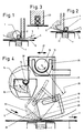
- FIGS. 1 to 3 Three of the known magnetic doctor devices with auxiliary devices are shown in FIGS. 1 to 3.
- 1 shows a magnetically pressed doctor blade 1 with a support bar 2, seen in the direction of movement 3, arranged behind the roller 1, either supporting the doctor blade 1 or the ink or paste bead or both.
- ink jam bar 4 or ink jam and sealing bar, which, viewed in the direction of movement 3, is arranged in the area in front of the doctor blade 1 and the ink 22 or paste in front of the roller, and which, depending on the dimension and location Distance to the application level from the template 5 or web 6), which affects the application process.
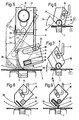
- a trough 14 is provided for supplying the substance to be applied, which can be suspended in a rail 28, that is to say can be inserted.
- the trough can be tilted about the axis 15 or guided along the trough 16 shown in broken lines.
- the substance 22 to be applied can be brought in front of the doctor element 8.
- the doctor element 8 is pivoted, as already mentioned, and as a result a working surface 29 can come into action which exerts pressure on the substance 22 to be applied.
- the doctor element 8 here consists of a non-magnetizable material, but a magnetizable bar 20 is inserted in a slot 21, so that the doctor edge 18 can be pressed against the template 5 or web 6 by the magnetic table 7.
- the substance supply is formed here.
- the pivot axis is designed here as a tube 30 and inserted into a profile body 31. In the profile body 31 there is a main channel 32 open against the tube 30, the ends of which open into a further channel 33, from which the substance to be applied then emerges via bores 34.
- a baffle or deflection strip 35 can also be present.
- a guide 9 is again provided in a strip 36, in which the displacement pin 10 is arranged movably on the connecting element.
- the actual doctor element is a roller 37 which is pressed against the web by the magnet 7.
- the surface 29 in turn serves to apply pressure to the medium to be applied.
- the squeegee element is formed by a pressure-elastic body 41 and the magnetizable mass 42 is formed by a round rod which bears against the pressure-elastic body 41.
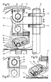
- FIG. 10 The design of the invention according to FIG. 10 is similar to that of FIGS. 4 and 5.
- the holder 24 By rotating the tubular axis 30 with the profile body 31, which is clamped on in two parts and e.g. is held together by screws 43 or by operating an adjusting nut 44 on a threaded rod 45, the holder 24 can be adjusted in height.
- a groove 46 is provided for the color exit, wherein the color exit can be directed partially or continuously horizontally or also obliquely downwards.
- the height can also be adjusted by an electric motor by means of the threaded rod 45.
- the device When the device is removed, it stands on the head and the profile body 31 rests on a bearing shell 48 and a channel 47 is provided, into which the remaining paint runs and can be easily removed.
- FIG. 12 again shows the lower part of FIG. 10 at different angles (once fully extended, once with dashed lines), which is given by the different height position of the displacement pin 10 on the connecting element 11.
- the design variant (a) is particularly economically applicable in sample and small production machines, the design variant (b) is preferred for large production machines.
- variant (a) can also be used in large-scale productions, advantageously in connection with stencils that print only very small sample details and, as a result, have a very low consumption of printing ink or application substance.
- doctor devices of the above-described embodiment variants (a) and (b) have the exact same application characteristics and can also be set in the same way, so that not only each embodiment variant (a) and (b) is in itself reproducible application results can be set, but that it is also possible to transfer application values that were achieved in the sample with devices of the embodiment variant (a) to the devices of the embodiment variant (b) and to be able to reproduce them in terms of production.
- design variants of this type are functional and that surprisingly some advantageous usage effects can be achieved with these design variants; for example, better adhesion of the printing ink or the substance to be applied to the doctor roller and, as a result, taking a larger quantity of substance into the application-effective area;
- the structuring of the roller surface also increases the ability to take along the traces of application substance remaining on the roller after application and carry them away through the gap or contact area existing between roller surface and slide bearing-like guide.
- the invention is not limited to the examples shown, in particular it is possible not to adjust the squeegee element by means of a sliding joint connection, but rather to e.g. subject separately to a translation or a rotation or to change the location at all.
- the scope of protection of the patent is determined by the content of the claims.
Landscapes
- Engineering & Computer Science (AREA)
- Mechanical Engineering (AREA)
- Coating Apparatus (AREA)
- Screen Printers (AREA)
- Measuring Or Testing Involving Enzymes Or Micro-Organisms (AREA)
- Application Of Or Painting With Fluid Materials (AREA)
- Paints Or Removers (AREA)
- Coloring (AREA)
- Treatment Of Fiber Materials (AREA)
- Liquid Crystal Substances (AREA)
- General Factory Administration (AREA)
Claims (23)
- Dispositif de raclage pour appliquer des dessins ou des couches sur ou pour teindre des bandes de tissu pour des métrages courts et/ou pour une production en grande série avec une barre profilée (8, 36) réalisée sous forme d'élément formant racle, ou retenant un élément formant racle (37, 40, 41), l'élément formant racle pouvant être appliqué par pression magnétiquement à la bande de tissu ou à un gabarit s'appliquant à la bande de tissu, et avec un longeron de support qui est relié par un élément de liaison (11) de façon articulée à la barre profilée (8, 36) où, par un pivotement du longeron de support (12) autour de son axe longitudinal et/ou par déplacement du longeron de support perpendiculairement à son axe longitudinal, la position de la barre profilée peut être modifiée, caractérisé en ce que la liaison articulée entre le longeron de support et la barre profilée est une liaison articulée coulissante (9, 10) et en ce que la barre profilée par suite du pivotement et/ou du coulissement du longeron de support est pivoteé autour de la ligne d'appui (18, 26) de l'élément formant racle sur la bande de tissu ou le gabarit ou dans le cas d'une barre profilée, qui retient de façon mobile une racle tournante, autour de l'axe de la racle tournante et, par conséquent, sa position angulaire par rapport au plan d'application (16) est modifiée, la position de la ligne d'appui n'étant pas modifiée pour une force magnétique donnée.
- Dispositif selon la revendication 1, caractérisé en ce que l'élément formant racle ou la barre profilée (8, 36, 40, 41) retenant l'élément formant racle peut être pivoté autour de la ligne d'appui (18, 26) ou autour d'un axe pivotant se trouvant au voisinage immédiat de cette ligne par une modification de la position de la liaison articulée coulissante.
- Dispositif selon la revendication 1 ou 2, caractérisé en ce que la position de la liaison articulée coulissante peut être modifiée par rapport au plan d'application.
- Dispositif selon l'une des revendications précédentes, caractérisé en ce que l'écart entre le longeron de support (12) et l'élément d'application peut être modifié.
- Dispositif selon la revendication 3, caractérisé en ce que la liaison articulée coulissante est déplaçable parallèlement au plan d'application.
- Dispositif selon la revendication 4, caractérisé en ce que la distance maximale entre le longeron de support et l'élément formant racle ou la barre profilée retenant l'élément formant racle est définie par la longueur de l'élément de liaison (11).
- Dispositif selon l'une des revendications précédentes, caractérisé en ce que le longeron de support peut tourner autour de son axe.
- Dispositif selon l'une des revendications précédentes, caractérisé en ce que le longeron de support est déplaçable par rapport au plan d'application.
- Dispositif selon l'une des revendications précédentes, caractérisé en ce que l'élément formant racle ou la barre profilée retenant l'élément formant racle est réalisé au moins en partie en un matériau pouvant être aimanté et est retenu magnétiquement par l'application de celui-ci aussi dans la position locale, c'est-à-dire vu en direction longitudinale.
- Dispositif selon l'une des revendications précédentes, caractérisé en ce que l'élément formant racle, de préférence un rouleau formant racle, est structuré à la surface.
- Dispositif selon l'une des revendications 1 à 9, caractérisé en ce que l'élément formant racle est constitué d'une barre pourvue d'un bord profilé.
- Dispositif selon l'une des revendications 1 à 9, caractérisé en ce que l'élément formant racle est constitué d'une tige profilée d'étalage, de préférence aussi avec une section transversale circulaire.
- Dispositif selon l'une des revendications 1 à 9, caractérisé en ce que l'élément formant racle est constitué par une lame de raclage élastique en flexion en métal ou en matière synthétique.
- Dispositif selon l'une des revendications 1 à 9, caractérisé en ce que l'élément formant racle est constitué par une barre de raclage élastique en pression et en flexion, par exemple en caoutchouc ou en matière synthétique.
- Dispositif selon l'une des revendications précédentes 1 à 9, caractérisé en ce que l'élément formant racle est un rouleau formant racle qui est disposé dans un évidement du type à palier coulissant de la barre profilée retenant l'élément formant racle.
- Dispositif selon l'une des revendications précédentes, caractérisé en ce que la barre profilée est réalisée au moins en partie en un matériau élastique ou en un matériau d'une rigidité propre réduite.
- Dispositif selon l'une des revendications précédentes, caractérisé en ce que l'élément formant racle est réalisé en un matériau qui ne peut pas être aimanté et est pourvu, le cas échéant, d'une barre constituée en un matériau pouvant être aimanté,le cas échéant, en une disposition morcelée.
- Dispositif selon l'une des revendications précédentes, caractérisé en ce que la substance est amenée par un dispositif d'amenée en forme de cuve ou d'auge qui est fixé au longeron de support, de préférence de façon pivotante ou insérable par poussée.
- Dispositif selon la revendication 18, caractérisé en ce que le dispositif d'amenée peut pivoter autour d'un axe.
- Dispositif selon l'une des revendications précédentes 1 à 17, caractérisé en ce que l'axe du longeron de support est réalisé sous forme de tuyau d'amenée de substance et présente des ouvertures de sortie réparties sur la longueur.
- Dispositif selon l'une des revendications précédentes 18 à 20, caractérisé en ce que le dispositif d'amenée fait saillie au moins sur un côté, sur un gabarit de cylindre ce qui permet le remplissage subséquent pendant le fonctionnement.
- Dispositif selon l'une des revendications précédentes, caractérisé en ce que l'élément formant racle et le longeron de support sont déplaçables dans au moins une direction en biais l'un vers l'autre.
- Dispositif selon l'une des revendications précédentes, caractérisé en ce que l'élément formant racle présente une sur face de retenue plane ou courbée.
Applications Claiming Priority (3)
| Application Number | Priority Date | Filing Date | Title |
|---|---|---|---|
| AT1943/89 | 1989-08-16 | ||
| AT1943/89A AT392745B (de) | 1989-08-16 | 1989-08-16 | Einrichtung und verfahren fuer bemusternde und/oder vollflaechige auftragungsprozesse auf kurze und beliebig lange warenbahnen |
| PCT/AT1990/000077 WO1991002650A1 (fr) | 1989-08-16 | 1990-07-31 | Dispositif et procede pour des processus d'application |
Publications (2)
| Publication Number | Publication Date |
|---|---|
| EP0438552A1 EP0438552A1 (fr) | 1991-07-31 |
| EP0438552B1 true EP0438552B1 (fr) | 1995-10-18 |
Family
ID=3524389
Family Applications (1)
| Application Number | Title | Priority Date | Filing Date |
|---|---|---|---|
| EP90910481A Expired - Lifetime EP0438552B1 (fr) | 1989-08-16 | 1990-07-31 | Dispositif et procede pour des processus d'application |
Country Status (8)
| Country | Link |
|---|---|
| US (1) | US5239922A (fr) |
| EP (1) | EP0438552B1 (fr) |
| JP (1) | JP2607311B2 (fr) |
| AT (2) | AT392745B (fr) |
| BR (1) | BR9006883A (fr) |
| DE (1) | DE59009798D1 (fr) |
| ES (1) | ES2080828T3 (fr) |
| WO (1) | WO1991002650A1 (fr) |
Families Citing this family (14)
| Publication number | Priority date | Publication date | Assignee | Title |
|---|---|---|---|---|
| DE9112032U1 (de) * | 1991-09-23 | 1993-01-28 | Zimmer, Johannes, Klagenfurt, Kärnten | Rakelgerät |
| DE9112033U1 (de) * | 1991-09-23 | 1993-01-28 | Zimmer, Johannes, Klagenfurt, Kärnten | Rakeleinrichtung |
| FR2700731B1 (fr) * | 1993-01-22 | 1995-04-07 | Dubuit Mach | Tête de raclage, notamment pour machine à imprimer à l'écran de soie. |
| US5510510A (en) * | 1994-05-10 | 1996-04-23 | Bristol-Meyers Squibb Company | Inhibitors of farnesyl protein transferase |
| DE29517098U1 (de) * | 1995-10-17 | 1997-02-13 | Zimmer, Johannes, Klagenfurt | Auftragungsvorrichtung |
| DE29517099U1 (de) * | 1995-10-17 | 1997-02-27 | Zimmer, Johannes, Klagenfurt | Auftragungsvorrichtung |
| US6217707B1 (en) | 1996-12-31 | 2001-04-17 | Kimberly-Clark Worldwide, Inc. | Controlled coverage additive application |
| US6231719B1 (en) | 1996-12-31 | 2001-05-15 | Kimberly-Clark Worldwide, Inc. | Uncreped throughdried tissue with controlled coverage additive |
| JP3798193B2 (ja) * | 1999-08-02 | 2006-07-19 | 理想科学工業株式会社 | 孔版印刷装置 |
| DE10358221A1 (de) * | 2003-12-12 | 2005-07-07 | Voith Paper Patent Gmbh | Rakelvorrichtung |
| DE102015208919A1 (de) * | 2015-05-13 | 2016-11-17 | Koenig & Bauer Ag | Rakeleinrichtung, Druckwerk sowie Verfahren zum Betreiben einer Rakeleinrichtung |
| CN107366115B (zh) * | 2017-06-22 | 2023-10-31 | 杭州三拓科技有限公司 | 一种染料化料装置 |
| CN112918084A (zh) * | 2021-01-22 | 2021-06-08 | 温州旺信贸易有限公司 | 一种方便调节刮墨角度和回墨量的丝网印刷刮墨装置 |
| CN119186921B (zh) * | 2024-11-26 | 2025-02-25 | 汕头市庆达机电设备有限公司 | 一种具备多种涂布方式的涂布头 |
Family Cites Families (5)
| Publication number | Priority date | Publication date | Assignee | Title |
|---|---|---|---|---|
| US3974766A (en) * | 1973-09-10 | 1976-08-17 | Peter Zimmer | Process for imprinting spaced-apart web sections with a composite pattern |
| AT376399B (de) * | 1981-12-07 | 1984-11-12 | Zimmer Johannes | Rakelvorrichtung |
| EP0126723A3 (fr) * | 1983-05-18 | 1986-10-29 | Svecia Silkscreen Maskiner AB | Procédé et dispositif pour le positionnement d'un second dessin provenant d'un dessin réalisé sur un pochoir, par rapport à un matériau destiné à porter ce dessin |
| JPH03501823A (ja) * | 1987-10-10 | 1991-04-25 | ツインマー,ヨハネス | 塗着装置 |
| EP0311728B1 (fr) * | 1987-10-10 | 1993-03-10 | Johannes Zimmer | Dispositif de raclage |
-
1989
- 1989-08-16 AT AT1943/89A patent/AT392745B/de not_active IP Right Cessation
-
1990
- 1990-07-31 US US07/659,285 patent/US5239922A/en not_active Expired - Fee Related
- 1990-07-31 JP JP2510625A patent/JP2607311B2/ja not_active Expired - Lifetime
- 1990-07-31 BR BR909006883A patent/BR9006883A/pt not_active IP Right Cessation
- 1990-07-31 WO PCT/AT1990/000077 patent/WO1991002650A1/fr not_active Ceased
- 1990-07-31 ES ES90910481T patent/ES2080828T3/es not_active Expired - Lifetime
- 1990-07-31 EP EP90910481A patent/EP0438552B1/fr not_active Expired - Lifetime
- 1990-07-31 DE DE59009798T patent/DE59009798D1/de not_active Expired - Fee Related
- 1990-07-31 AT AT90910481T patent/ATE129187T1/de not_active IP Right Cessation
Also Published As
| Publication number | Publication date |
|---|---|
| EP0438552A1 (fr) | 1991-07-31 |
| JPH04506940A (ja) | 1992-12-03 |
| BR9006883A (pt) | 1991-11-05 |
| JP2607311B2 (ja) | 1997-05-07 |
| ATE129187T1 (de) | 1995-11-15 |
| ATA194389A (de) | 1990-11-15 |
| WO1991002650A1 (fr) | 1991-03-07 |
| US5239922A (en) | 1993-08-31 |
| DE59009798D1 (de) | 1995-11-23 |
| ES2080828T3 (es) | 1996-02-16 |
| AT392745B (de) | 1991-05-27 |
Similar Documents
| Publication | Publication Date | Title |
|---|---|---|
| EP0438552B1 (fr) | Dispositif et procede pour des processus d'application | |
| DE19718113C2 (de) | Rakelvorrichtung zum Siebdrucken | |
| EP0311728B1 (fr) | Dispositif de raclage | |
| DE2950025A1 (de) | Mit wasser oder einem gemisch aus wasser und alkohol arbeitendes feuchtwerk fuer offset-druckmaschinen | |
| DE3689176T2 (de) | Rakelblattvorrichtung für einen Beschichtungsapparat. | |
| CH652943A5 (de) | Vorrichtung zum streichen von papierbahnen. | |
| EP0408704B1 (fr) | Installation d'application de substances sur une bande de materiau | |
| CH668922A5 (de) | Verfahren und vorrichtung fuer die streichbeschichtung einer sich bewegenden materialbahn. | |
| EP0602431A1 (fr) | Dispositif de racle d'essuyage | |
| DE4444779B4 (de) | Vorrichtung zum Auftragen eines flüssigen oder pastösen Mediums auf eine laufende Materialbahn, insbesondere aus Papier oder Karton | |
| EP0149841A2 (fr) | Procédé et dispositif pour encrer le cliché d'un cylindre porte-plaque d'une machine à imprimer rotative | |
| EP0235204B1 (fr) | Dispositif d'application et de dosage d'agents fluides sur une bande ou sur un cylindre | |
| EP0311730B1 (fr) | Dispositif de raclage | |
| DE69119650T2 (de) | Ätzmaterial-Beschichtungsvorrichtung | |
| DE2804801A1 (de) | Gummituchwaschvorrichtung | |
| EP0135618A2 (fr) | Machine de sérigraphie | |
| DE4213669A1 (de) | Einrichtung zum Anstellen eines Rakelbalkens an eine farbabgebende Walze einer Rollenrotationsdruckmaschine | |
| DE2754663A1 (de) | Vorrichtung zum auftragen von medien in ein substrat | |
| DE29716541U1 (de) | Vorrichtung zum Auftragen von Flüssigkeiten auf ein Substrat | |
| DE102006008002A1 (de) | Farbwerk, sowie Verfahren zur sujetspezifischen Abstimmung eines Konfigurationszustandes desselben | |
| DE69527024T2 (de) | Verfahren und Aufbau zur Überwachung des Beschichtungsprofils in Beschichtungsvorrichtungen, die auf einem Auftrag mit kurzer Wartezeit basieren | |
| AT401480B (de) | Rakelgerät zum auftragen bzw. auftragen und abrakeln bzw. zum dosierten auftragen fliessfähiger oder streichfähiger substanzen | |
| EP0463142B1 (fr) | Racloir et dispositif de raclage a pression magnetique, particulierement avec cylindre perfore | |
| DE2903415C2 (fr) | ||
| DE69808817T2 (de) | Rakel mit festem Trägerteil |
Legal Events
| Date | Code | Title | Description |
|---|---|---|---|
| PUAI | Public reference made under article 153(3) epc to a published international application that has entered the european phase |
Free format text: ORIGINAL CODE: 0009012 |
|
| 17P | Request for examination filed |
Effective date: 19910409 |
|
| AK | Designated contracting states |
Kind code of ref document: A1 Designated state(s): AT CH DE ES FR GB IT LI NL |
|
| 17Q | First examination report despatched |
Effective date: 19930211 |
|
| GRAA | (expected) grant |
Free format text: ORIGINAL CODE: 0009210 |
|
| AK | Designated contracting states |
Kind code of ref document: B1 Designated state(s): AT CH DE ES FR GB IT LI NL |
|
| PG25 | Lapsed in a contracting state [announced via postgrant information from national office to epo] |
Ref country code: GB Effective date: 19951018 Ref country code: FR Effective date: 19951018 |
|
| REF | Corresponds to: |
Ref document number: 129187 Country of ref document: AT Date of ref document: 19951115 Kind code of ref document: T |
|
| REF | Corresponds to: |
Ref document number: 59009798 Country of ref document: DE Date of ref document: 19951123 |
|
| ITF | It: translation for a ep patent filed | ||
| REG | Reference to a national code |
Ref country code: ES Ref legal event code: FG2A Ref document number: 2080828 Country of ref document: ES Kind code of ref document: T3 |
|
| EN | Fr: translation not filed | ||
| GBV | Gb: ep patent (uk) treated as always having been void in accordance with gb section 77(7)/1977 [no translation filed] |
Effective date: 19951018 |
|
| PLBE | No opposition filed within time limit |
Free format text: ORIGINAL CODE: 0009261 |
|
| STAA | Information on the status of an ep patent application or granted ep patent |
Free format text: STATUS: NO OPPOSITION FILED WITHIN TIME LIMIT |
|
| 26N | No opposition filed | ||
| PGFP | Annual fee paid to national office [announced via postgrant information from national office to epo] |
Ref country code: CH Payment date: 19990709 Year of fee payment: 10 |
|
| PG25 | Lapsed in a contracting state [announced via postgrant information from national office to epo] |
Ref country code: LI Free format text: LAPSE BECAUSE OF NON-PAYMENT OF DUE FEES Effective date: 20000731 Ref country code: CH Free format text: LAPSE BECAUSE OF NON-PAYMENT OF DUE FEES Effective date: 20000731 |
|
| REG | Reference to a national code |
Ref country code: CH Ref legal event code: PL |
|
| PGFP | Annual fee paid to national office [announced via postgrant information from national office to epo] |
Ref country code: AT Payment date: 20040722 Year of fee payment: 15 |
|
| PGFP | Annual fee paid to national office [announced via postgrant information from national office to epo] |
Ref country code: ES Payment date: 20040726 Year of fee payment: 15 |
|
| PGFP | Annual fee paid to national office [announced via postgrant information from national office to epo] |
Ref country code: DE Payment date: 20040729 Year of fee payment: 15 |
|
| PGFP | Annual fee paid to national office [announced via postgrant information from national office to epo] |
Ref country code: NL Payment date: 20040731 Year of fee payment: 15 |
|
| PG25 | Lapsed in a contracting state [announced via postgrant information from national office to epo] |
Ref country code: IT Free format text: LAPSE BECAUSE OF NON-PAYMENT OF DUE FEES;WARNING: LAPSES OF ITALIAN PATENTS WITH EFFECTIVE DATE BEFORE 2007 MAY HAVE OCCURRED AT ANY TIME BEFORE 2007. THE CORRECT EFFECTIVE DATE MAY BE DIFFERENT FROM THE ONE RECORDED. Effective date: 20050731 Ref country code: AT Free format text: LAPSE BECAUSE OF NON-PAYMENT OF DUE FEES Effective date: 20050731 |
|
| PG25 | Lapsed in a contracting state [announced via postgrant information from national office to epo] |
Ref country code: ES Free format text: LAPSE BECAUSE OF NON-PAYMENT OF DUE FEES Effective date: 20050801 |
|
| PG25 | Lapsed in a contracting state [announced via postgrant information from national office to epo] |
Ref country code: NL Free format text: LAPSE BECAUSE OF NON-PAYMENT OF DUE FEES Effective date: 20060201 Ref country code: DE Free format text: LAPSE BECAUSE OF NON-PAYMENT OF DUE FEES Effective date: 20060201 |
|
| NLV4 | Nl: lapsed or anulled due to non-payment of the annual fee |
Effective date: 20060201 |
|
| REG | Reference to a national code |
Ref country code: ES Ref legal event code: FD2A Effective date: 20050801 |