EP0438552B1 - Device and process for carrying out application operations - Google Patents
Device and process for carrying out application operations Download PDFInfo
- Publication number
- EP0438552B1 EP0438552B1 EP90910481A EP90910481A EP0438552B1 EP 0438552 B1 EP0438552 B1 EP 0438552B1 EP 90910481 A EP90910481 A EP 90910481A EP 90910481 A EP90910481 A EP 90910481A EP 0438552 B1 EP0438552 B1 EP 0438552B1
- Authority
- EP
- European Patent Office
- Prior art keywords
- applicator element
- applicator
- support member
- profiled strip
- strip
- Prior art date
- Legal status (The legal status is an assumption and is not a legal conclusion. Google has not performed a legal analysis and makes no representation as to the accuracy of the status listed.)
- Expired - Lifetime
Links
- 238000000034 method Methods 0.000 title abstract description 12
- 230000008569 process Effects 0.000 title abstract description 8
- 239000000126 substance Substances 0.000 claims abstract description 20
- 239000000463 material Substances 0.000 claims abstract description 14
- 238000011031 large-scale manufacturing process Methods 0.000 claims abstract description 10
- 238000000576 coating method Methods 0.000 claims abstract 2
- 238000004043 dyeing Methods 0.000 claims abstract 2
- 230000008859 change Effects 0.000 claims description 4
- 238000003825 pressing Methods 0.000 claims description 2
- 239000004744 fabric Substances 0.000 claims 4
- 239000002184 metal Substances 0.000 claims 1
- 238000004519 manufacturing process Methods 0.000 abstract description 18
- 238000007639 printing Methods 0.000 abstract description 9
- 239000011248 coating agent Substances 0.000 abstract 1
- 239000000976 ink Substances 0.000 description 20
- 238000013461 design Methods 0.000 description 10
- 238000000059 patterning Methods 0.000 description 6
- 238000004140 cleaning Methods 0.000 description 5
- 238000006073 displacement reaction Methods 0.000 description 5
- 238000005516 engineering process Methods 0.000 description 4
- 230000008901 benefit Effects 0.000 description 3
- 230000000694 effects Effects 0.000 description 3
- XLYOFNOQVPJJNP-UHFFFAOYSA-N water Substances O XLYOFNOQVPJJNP-UHFFFAOYSA-N 0.000 description 3
- 239000003086 colorant Substances 0.000 description 2
- 238000010276 construction Methods 0.000 description 2
- 230000006872 improvement Effects 0.000 description 2
- 238000009434 installation Methods 0.000 description 2
- 238000005192 partition Methods 0.000 description 2
- 238000003860 storage Methods 0.000 description 2
- 238000012546 transfer Methods 0.000 description 2
- 230000009471 action Effects 0.000 description 1
- 239000011324 bead Substances 0.000 description 1
- 238000005452 bending Methods 0.000 description 1
- 230000007812 deficiency Effects 0.000 description 1
- 238000011161 development Methods 0.000 description 1
- 238000009826 distribution Methods 0.000 description 1
- 238000007730 finishing process Methods 0.000 description 1
- 238000011089 mechanical engineering Methods 0.000 description 1
- 238000010327 methods by industry Methods 0.000 description 1
- 239000003973 paint Substances 0.000 description 1
- 238000012545 processing Methods 0.000 description 1
- 230000000284 resting effect Effects 0.000 description 1
- 238000005070 sampling Methods 0.000 description 1
- 238000007789 sealing Methods 0.000 description 1
- 238000012360 testing method Methods 0.000 description 1
- 239000004753 textile Substances 0.000 description 1
- 238000009988 textile finishing Methods 0.000 description 1
- 238000013519 translation Methods 0.000 description 1
Images
Classifications
-
- B—PERFORMING OPERATIONS; TRANSPORTING
- B41—PRINTING; LINING MACHINES; TYPEWRITERS; STAMPS
- B41F—PRINTING MACHINES OR PRESSES
- B41F15/00—Screen printers
- B41F15/14—Details
- B41F15/40—Inking units
- B41F15/42—Inking units comprising squeegees or doctors
- B41F15/426—Inking units comprising squeegees or doctors the squeegees or doctors being magnetically attracted
Definitions
- the ink supply according to the invention can be used to achieve a significant improvement in economy.
- Setup and water savings are also associated with the ink or substance supply, which is simplified in accordance with the invention; the cleaning of pumps and pipes is very water-consuming.
- the printing ink or substance required in each case can be prepared exactly as required, so that no losses occur.
- the resulting savings are on average about 5 l / stencil and color.
- the manually operated feed device also makes it possible to clean the stencil and, if necessary, also the squeegee device in the installed state.
- the last required color trough is pulled out, then a fresh trough with cleaning water is pushed in, briefly rinsed and cleaned with a rotating stencil and then a trough filled with fresh color is used for the next color setting.
- patterning several different colors can be printed side by side at the same time, by inserting partitions that can be moved into the trough. With a rod attached to it, a sliding partition can be used as a cleaning slide for the trough to save color and water.
- a squeegee device with a pivotable or changed in height support beam on which a holding element is fixedly known.
- the support bar is connected here with a profile bar, which holds a doctor element, via the holding element.
- the articulated connection between the support beam and profile strip is a sliding joint connection and the profile strip as a result of the pivoting and / or displacement of the support beam around the support line of the doctor element on the web or the template or on a profile bar that holds a roller squeegee, is pivoted about the axis of the roller squeegee and thus its angular position is changed with respect to the application plane, the position of the support line remains unchanged for a given magnetic force.
- the invention is characterized by treading a fundamentally new path: So far it has been customary in doctor blades that the axial position of the doctor element is determined by the doctor device construction; According to the invention, the axial position of the squeegee element is determined exclusively by magnetic force or magnetic devices, i.e. the squeegee device is designed to match the magnetic technology and does not determine the position of the squeegee bar or squeegee holding bar or squeegee element, but only the angular position of the squeegee bar in relation to the application plane. Since only small quantities of material are used in the setting of the setting values, there are no major losses and, on the other hand, cleaning can be carried out quickly without major interruptions when changing templates.
- the settings can also be made with only one template device, although when processing a long web of material, the templates then work in succession, as is known per se.
- the setting values found during the patterning with only one circular template device can easily be transferred to the individual template stations.
- the devices known hitherto not only is the position of the doctor roller, as seen in the direction of movement, determined by a mechanical device, but the axial position of the doctor element is also predetermined by the doctor device.
- the magnetic force is used as a doctor contact pressure, occasionally also as a subordinate assistant for determining the position, but always in conjunction with mechanical means for determining the position.
- a second Assign main work function the magnetic force or the device generating the magnetic force is assigned the work function of fixing the position alone, without using mechanical aids.
- the axial position of a magnetically pressed roller doctor blade or scraper bar is determined exclusively by magnetic force.
- these connecting parts which control the angular position by sliding contact are also assigned a holding function which does not act in the operating state but only outside the operating state.
- This auxiliary function of holding which cannot or cannot be set in the operating state, has the effect that the entire application device - in which the substance supply is preferably also integrated - can be handled in one piece. This simplifies the installation and removal of the device, enables the squeegee element to be brought into the approximately suitable position for the desired magnetic force-induced operating state during installation, and enables also to be able to lift the squeegee device in the event of a brief interruption in operation and magnetic field switch-off (in the position contactless to the application level or template).
- FIGS. 1 to 3 Three of the known magnetic doctor devices with auxiliary devices are shown in FIGS. 1 to 3.
- 1 shows a magnetically pressed doctor blade 1 with a support bar 2, seen in the direction of movement 3, arranged behind the roller 1, either supporting the doctor blade 1 or the ink or paste bead or both.
- ink jam bar 4 or ink jam and sealing bar, which, viewed in the direction of movement 3, is arranged in the area in front of the doctor blade 1 and the ink 22 or paste in front of the roller, and which, depending on the dimension and location Distance to the application level from the template 5 or web 6), which affects the application process.
- a trough 14 is provided for supplying the substance to be applied, which can be suspended in a rail 28, that is to say can be inserted.
- the trough can be tilted about the axis 15 or guided along the trough 16 shown in broken lines.
- the substance 22 to be applied can be brought in front of the doctor element 8.
- the doctor element 8 is pivoted, as already mentioned, and as a result a working surface 29 can come into action which exerts pressure on the substance 22 to be applied.
- the doctor element 8 here consists of a non-magnetizable material, but a magnetizable bar 20 is inserted in a slot 21, so that the doctor edge 18 can be pressed against the template 5 or web 6 by the magnetic table 7.
- the substance supply is formed here.
- the pivot axis is designed here as a tube 30 and inserted into a profile body 31. In the profile body 31 there is a main channel 32 open against the tube 30, the ends of which open into a further channel 33, from which the substance to be applied then emerges via bores 34.
- a baffle or deflection strip 35 can also be present.
- a guide 9 is again provided in a strip 36, in which the displacement pin 10 is arranged movably on the connecting element.
- the actual doctor element is a roller 37 which is pressed against the web by the magnet 7.
- the surface 29 in turn serves to apply pressure to the medium to be applied.
- the squeegee element is formed by a pressure-elastic body 41 and the magnetizable mass 42 is formed by a round rod which bears against the pressure-elastic body 41.
- FIG. 10 The design of the invention according to FIG. 10 is similar to that of FIGS. 4 and 5.
- the holder 24 By rotating the tubular axis 30 with the profile body 31, which is clamped on in two parts and e.g. is held together by screws 43 or by operating an adjusting nut 44 on a threaded rod 45, the holder 24 can be adjusted in height.
- a groove 46 is provided for the color exit, wherein the color exit can be directed partially or continuously horizontally or also obliquely downwards.
- the height can also be adjusted by an electric motor by means of the threaded rod 45.
- the device When the device is removed, it stands on the head and the profile body 31 rests on a bearing shell 48 and a channel 47 is provided, into which the remaining paint runs and can be easily removed.
- FIG. 12 again shows the lower part of FIG. 10 at different angles (once fully extended, once with dashed lines), which is given by the different height position of the displacement pin 10 on the connecting element 11.
- the design variant (a) is particularly economically applicable in sample and small production machines, the design variant (b) is preferred for large production machines.
- variant (a) can also be used in large-scale productions, advantageously in connection with stencils that print only very small sample details and, as a result, have a very low consumption of printing ink or application substance.
- doctor devices of the above-described embodiment variants (a) and (b) have the exact same application characteristics and can also be set in the same way, so that not only each embodiment variant (a) and (b) is in itself reproducible application results can be set, but that it is also possible to transfer application values that were achieved in the sample with devices of the embodiment variant (a) to the devices of the embodiment variant (b) and to be able to reproduce them in terms of production.
- design variants of this type are functional and that surprisingly some advantageous usage effects can be achieved with these design variants; for example, better adhesion of the printing ink or the substance to be applied to the doctor roller and, as a result, taking a larger quantity of substance into the application-effective area;
- the structuring of the roller surface also increases the ability to take along the traces of application substance remaining on the roller after application and carry them away through the gap or contact area existing between roller surface and slide bearing-like guide.
- the invention is not limited to the examples shown, in particular it is possible not to adjust the squeegee element by means of a sliding joint connection, but rather to e.g. subject separately to a translation or a rotation or to change the location at all.
- the scope of protection of the patent is determined by the content of the claims.
Landscapes
- Engineering & Computer Science (AREA)
- Mechanical Engineering (AREA)
- Coating Apparatus (AREA)
- Screen Printers (AREA)
- Measuring Or Testing Involving Enzymes Or Micro-Organisms (AREA)
- Application Of Or Painting With Fluid Materials (AREA)
- Paints Or Removers (AREA)
- Coloring (AREA)
- Treatment Of Fiber Materials (AREA)
- Liquid Crystal Substances (AREA)
- General Factory Administration (AREA)
Abstract
Description
In der Durchführung bemusternder oder vollflächig auftragender Veredelungs-Prozesse auf bahnenförmigem Material gibt es in der Praxis sehr unterschiedliche Anforderungen, und zwar unterschiedlich sowohl hinsichtlich Warenqualitäten und prozeßtechnischer Erfordernisse als auch unterschiedlich in bezug auf jeweils herzustellende Stücklängen.In practice, there are very different requirements when carrying out patterning or full-surface finishing processes on sheet-like material, namely differently both with regard to the quality of the goods and the process requirements, and differently with regard to the lengths of the piece to be produced.
Es gibt Produktionsarten in der Textilveredelungs-Industrie, bei welchen nur jeweils geringe Stücklhängen herzustellen sind, so z.B. Druckstoff für Krawatten. Es gibt auch Produktionsarten mit Auftragsgrößen mit einigen 100 Metern und außerdem gibt es auch Großaufträge von jeweils mehreren 1000 oder 10 000 Metern, die mit jeweils gleicher prozeßtechnischer Einstellung bzw. gewünschten gleichen Auftragungsergebnissen hergestellt werden sollen.There are types of production in the textile finishing industry in which only small piece lengths can be produced, e.g. Printing material for ties. There are also types of production with order sizes of a few 100 meters and there are also large orders of several 1000 or 10,000 meters each, which are to be produced with the same process engineering settings or the same order results as desired.
Eine z.B. in der Textildruckpraxis seit jeher bestehende Forderung ist die des sogenannten Ausmusterns eines neuen Designs in unterschiedlichen Farbkombinationen auf jeweils möglichst kurzen Warenstücken. Aus einer Vielzahl solcher kurzen Musterstücke werden in der Regel einige als Grundlagen für Großaufträge ausgewählt.A e.g. In textile printing practice, there has always been a requirement for the so-called retirement of a new design in different color combinations on the shortest possible pieces of goods. A large number of such short sample pieces are usually selected as the basis for large orders.
In der Praxis stehen dem Umsetzungsprozeß von musterungsmäßig hergestellten kleinen Stücken auf Großproduktion erhebliche Schwierigkeiten entgegen, für die es bislang noch keine den Anforderungen der Praxis voll entsprechenden Verfahren und Einrichtungen gibt. Es ist Aufgabe der vorliegenden Erfindung vorbeschriebene Mängel zu beheben und es ist durch diese Erfindung auch eine generelle Anhebung des Qualitäts-Niveaus von Schablonenbemusterungs- und vollflächig auftragenden Veredelungsprozessen gelungen.In practice, there are considerable difficulties in the process of converting small pieces produced according to the sample to large-scale production, for which there are as yet no processes and facilities that fully meet the requirements of practice. It is an object of the present invention to remedy the deficiencies described above, and this invention has also succeeded in generally increasing the quality level of stencil patterning and refinement processes that apply over the entire surface.
Von den derzeit bestehenden Schwierigkeiten der Umsetzung von Kleinproduktion bzw. Musterung auf Großproduktion sind zwei besonders hervorzuheben: Die Technik der Farb- bzw. Substanzzuführung und die Auftragungs- bzw. Rakeltechnik.Two of the currently existing difficulties in converting small-scale production or patterning to large-scale production are particularly noteworthy: the technology of ink or substance supply and the application or doctor blade technology.
Bei der Herstellung von kurzen Musterstücken bzw. Kleinst- und Kleinproduktion ist es üblich bzw. erforderlich die Druckfarben von Hand aus zur Auftragungsstelle zuzuführen, d.h. dem Rakelgerät vorzugeben. Bei Großproduktion sind automatisch arbeitende Zuführungssysteme üblich. Ähnlich verhält es sich mit den Rakelgeräten für Musterungs- und Kleinproduktionszwecke. Es werden zwecks rascherer Handhabung und zur Erzielung kurzer Umrüstzeiten einfache Handauftragungsgeräte bevorzugt, in Großproduktionsmaschinen werden umständlicher zu handhabende bzw. anzubauende mechanisch zu fixierende, genau einzustellende Rakelgeräte verwendet. Vorbeschriebene Unterschiedlichkeiten in der Farbzuführung und Rakeltechnik haben fast immer gravierende Qualitätsunterschiede im Bemusterungs- bzw. Veredelungsergebnis zur Folge.When producing short sample pieces or small and small-scale production, it is customary or necessary to feed the printing inks to the application point by hand, i.e. to specify the squeegee. Automatic feed systems are common in large-scale production. The situation is similar with the doctor blades for sample and small production purposes. For faster handling and to achieve short changeover times, simple manual application devices are preferred; in large production machines, doctoring devices that are more difficult to handle or to assemble are used. The above-mentioned differences in ink supply and doctor blade technology almost always result in serious quality differences in the sampling or finishing result.
Der Praktiker hat oft große Mühe, die ihm für die Großproduktion vorgelegten Musterstücke in allen Qualitätskriterien mustergetreu in die Großproduktion umzusetzen. Oft müssen sämtliche Farbkonzentrationen, Farbviskositäten und Rakelgeräteeinstellungen für die Großproduktion neu erarbeitet werden, weil die für die Musterung maßgeblichen Parameter nicht übertragbar sind. Die Erarbeitung der neuen praxisgültigen Parameter ist meistens sehr arbeitsintensiv und zeitaufwendig und durch die damit verbundenen Stillstandzeiten großer Produktionsanlagen sehr unwirtschaftlich. Das Erarbeiten der vorlagegetreuen Ergebnisse bedingt meist auch erhebliche Verlustmengen an Ware und aufzutragenden Substanzen. Es entsteht ein relativ hoher Anteil an Ausschußware und qualitätsgeminderter Produktion.The practitioner often has great difficulty in converting the sample pieces presented to him for the large-scale production into the large-scale production in all quality criteria. Often, all ink concentrations, ink viscosities and doctor blade settings have to be redesigned for large-scale production because the parameters that are decisive for the patterning are not transferable. The development of the new, practically valid parameters is usually very labor-intensive and time-consuming and very uneconomical due to the associated downtimes of large production plants. Elaborating the results true to the template usually also results in considerable loss of goods and substances to be applied. There is a relatively high proportion of rejects and reduced quality production.
Manche Druckerei- bzw. Veredelungsbetriebe verzichten sogar auf die an sich technisch und wirtschaftlich richtige Möglichkeit der Kleinmusterung, indem sie ihre hochwertigen Großproduktionsanlagen auch schon für Musterungszwecke benützen und um dadurch vorbeschriebenes Umsetzungsproblem ( auf Kosten der Rentabilität ) zu vermeiden.Some printing and finishing companies even dispense with the technically and economically correct option of small samples by using their high-quality large-scale production systems for sample purposes and thereby avoiding the above-mentioned implementation problem (at the expense of profitability).
Den Erfindungsgedanken erweiternd, ist es gelungen,daß auch in Großproduktionsmaschinen eine händisch zu betätigende bzw. handhabungs- und reinigungsvereinfachte Farbzuführungseinrichtung angewendet werden kann.Expanding the idea of the invention, it has been possible to use an ink feed device which can be operated manually or is simplified in terms of handling and cleaning, even in large production machines.
Erfindungsgemäß besteht nunmehr auch die Möglichkeit der Übertragbarkeit von Einstellwerten, die mit der Einstellungsmethode bzw. Ausführungsvariante "Verschwenken der Rakelleiste durch axiales Verdrehen des Tragholmes" erarbeitet wurden (Muster, Kleinproduktion) auf die Einstellungsmethode bzw. Ausführungsvariante "Verschwenken der Rakelleiste durch Veränderung der Distanz des Tragholmes zur Auftragsfläche"; dieselbe Übertragbarkeit besteht auch in der umgekehrten Folge.According to the invention, there is now also the possibility of transferring setting values which have been worked out using the setting method or embodiment variant "pivoting the doctor blade bar by axially rotating the support bar" (sample, small-scale production) to the setting method or embodiment variant "pivoting the doctor blade bar by changing the distance of the Tragholmes to the order area "; the same transferability also exists in the reverse order.
Zusammenfassend bietet das Arbeitsverfahren mit der erfindungsgemäßen Einrichtung folgende Möglichkeiten der Übertragbarkeit bzw. Reproduzierbarkeit:
- 1. Reproduzierbarkeit bzw. Übertragbarkeit mit der gleichen Einrichtung bzw. gleichen Ausführungsform, wie z.B. für Wiederholungsaufträge und sogenannte Coloritänderungen (Abdrucken mit der gleichen Schablone, nur mit anderen Farben);
- 2. Übertragbarkeit händischer in mechanisiert bzw. automatisiert erfolgender Einstellung;
- 3. Übertragbarkeit von der Einstellungsart "Verdrehen" auf die Einstellungsart "Distanzveränderung";
- 4. Übertragbarkeit von Arbeitsverfahren "Farbzuführung händisch" auf "Farb- bzw. Substanzzuführung mechanisch bzw. automatisiert";
- 5. Übertragbarkeit mit gleichzeitig erfolgender, mehrfacher Arbeitsverfahrenumstellung, z.B. von Einstellung
- a) händisch,
- b) durch Verdrehen der Achse und
- c) händische Substanzzuführung auf
- aa) Einstellung automatisiert,
- bb) Winkeleinstellung durch Distanzveränderung und
- cc) Substanzzuführung automatisiert.
- 1. Reproducibility or transferability with the same device or the same embodiment, such as for repeat orders and so-called color changes (printing with the same template, only with different colors);
- 2. Transferability by hand in mechanized or automated setting;
- 3. Transferability from the "Twist" setting type to the "Distance change" setting type;
- 4. Transferability of working procedures "ink feed manually" to "ink or substance feed mechanically or automatically";
- 5. Transferability with simultaneous, multiple work process changes, eg hiring
- a) by hand,
- b) by turning the axis and
- c) manual substance supply
- aa) setting automated,
- bb) angle adjustment by changing the distance and
- cc) automated substance delivery.
Derartige Einstellungs- und Ergebnisübertragungen sind, vergleichend mit dem bisher bekannten Stand der Technik, neu.Such setting and result transfers are new compared to the previously known prior art.
Wenn mit den Großproduktionsmaschinen Musterungs- oder Kleinproduktionsdrucke gemacht werden oder, was auch sehr wichtig ist und in der Praxis sehr häufig vorkommt, innerhalb eines hochfärbigen Designs von z.B. zehn Schablonen nur drei bis fünf Schablonen großflächig geöffnet sind und einen dementsprechend großen,zweckmäßigerweise automatisch zu steuernden Farbverbrauch haben, während die restlichen z.B. fünf bis sieben Schablonen nur kleine Musteranteile drucken und dementsprechend nur geringen Farbverbrauch haben, so kann durch die erfindungsgemäß bewirkte Farbzuführung eine bedeutende Verbesserung der Wirtschaftlichkeit erzielt werden. Mit der erfindungsgemäß vereinfacht erfolgenden Farb- bzw. Substanzzuführung ist auch Rüstzeit-und Wasserersparnis verbunden; die Reinigung von Pumpen und Rohrleitungen ist sehr wasseraufwendig.If sample or small production prints are made with the large production machines or, which is also very important and occurs very frequently in practice, only three to five stencils are opened over a large area within a high-color design of ten stencils, for example are and have a correspondingly large, expediently automatically controlled ink consumption, while the remaining five to seven stencils, for example, print only small sample portions and accordingly have only low ink consumption, the ink supply according to the invention can be used to achieve a significant improvement in economy. Setup and water savings are also associated with the ink or substance supply, which is simplified in accordance with the invention; the cleaning of pumps and pipes is very water-consuming.
Für Musterungen mit dem händischen Zuführungssystem kann die jeweils erforderliche Druckfarbe bzw. Substanz genau bedarfsgerecht zubereitet werden, so daß keine Verlustmengen entstehen. Die daraus resultierende Ersparnis beträgt durchschnittlich etwa 5 l/Schablone und Farbstellung. Die händisch betätigte Zuführungseinrichtung macht auch das Reinigen der Schablone und gegebenenfalls auch des Rakelgerätes im eingebauten Zustand möglich. Der zuletzt benötigte Farbtrog wird hinausgezogen, dann ein frischer Trog mit Reinigungswasser eingeschoben, kurz gespült und bei drehender Schablone gereinigt und sodann ein mit frischer Farbe gefüllter Trog für die nächste Farbstellung eingesetzt. Beim Mustern können mehrere verschiedene Farben nebeneinander gleichzeitig gedruckt werden, dadurch daß in den Trog verschiebbare Trennwände eingesetzt werden. Mit einer daran befestigten Stange kann eine verschiebbare Trennwand farb- und wassersparend auch als Reinigungsschieber für den Trog verwendet werden.For samples with the manual feed system, the printing ink or substance required in each case can be prepared exactly as required, so that no losses occur. The resulting savings are on average about 5 l / stencil and color. The manually operated feed device also makes it possible to clean the stencil and, if necessary, also the squeegee device in the installed state. The last required color trough is pulled out, then a fresh trough with cleaning water is pushed in, briefly rinsed and cleaned with a rotating stencil and then a trough filled with fresh color is used for the next color setting. When patterning, several different colors can be printed side by side at the same time, by inserting partitions that can be moved into the trough. With a rod attached to it, a sliding partition can be used as a cleaning slide for the trough to save color and water.
Bisher werden nicht nur Auftragungsgeräte mit mechanisch wirkender Anpreßkraft sondern auch solche, die mit magnetisch bewirkter Rakelanpressung arbeiten, möglichst biegesteif konstruiert. Dies sowohl betreffend den oberen Geräteteil bzw. Tragholm, an dem das eigentliche Rakelelement befestigt ist, als ebenso auch das eigentliche Rakelgerät, das das Rakelelement hält oder zumindest berührt, wie z.B. Rakelgeräteleisten in Verbindung mit Rollrakeln. Wurden bisher möglichst biegesteife Konstruktionen von Rakelgeräten aller Art angestrebt, so ist die erfindungsgemäße Einrichtung im Gegensatz dazu und zugleich auch erfindungskennzeichnend, so konstruiert, daß für die Konstruktion der Rakelleiste bzw. Rakelhalteleiste ein biegbares Material verwendet wird. Dies mit dem vorteilhaften Effekt der Anpassung der Profilleiste an das Reakelelement und mit diesem gemeinsam an die Auftragsebene bzw. Schablone.So far, not only application devices with a mechanically acting contact pressure, but also those that work with magnetically effected squeegee pressure have been designed to be as rigid as possible. This applies both to the upper part of the device or support beam to which the actual doctor element is attached, and also to the actual doctor device that holds or at least touches the doctor element, such as doctor blade strips in connection with roller doctor blades. While the most rigid designs of doctor blade devices of all kinds have been sought, the device according to the invention is in contrast to this and at the same time also characteristic of the invention, constructed in such a way that a flexible material is used for the construction of the squeegee strip or squeegee holding strip. This with the advantageous effect of adapting the profile strip to the rake element and together with this to the application level or template.
Aus der EP-A 311 728 ist bereits eine Rakeleinrichtung mit einem verschwenkbaren oder in seiner Höhenlage veränderten Tragholm, an dem ein Halteelement fest montiert ist, bekannt. Über das Halteelement ist hier der Tragholm mit einer Profilleiste verbunden, die ein Rakelelement hält. Zwischen Halteelement und Profilleiste findet sich ein Gelenk, das eine Schwenkbewegung zwischen Halteelement und Profilleiste zuläßt.From EP-A 311 728 a squeegee device with a pivotable or changed in height support beam on which a holding element is fixedly known. The support bar is connected here with a profile bar, which holds a doctor element, via the holding element. There is a joint between the holding element and the profile strip, which allows a pivoting movement between the holding element and the profile strip.
Ausgehend von der genannten EP-A 311 728 wird jetzt bei einer Rakeleinrichtung gemäß dem Oberbegriff des Anspruches 1 vorgeschlagen, daß die gelenkige Verbindung zwischen Tragholm und Profilleiste eine Schiebegelenkverbindung ist und die Profilleiste infolge des Verschwenkens und/oder Verschiebens des Tragholmes um die Auflagelinie des Rakelementes auf der Warenbahn bzw. der Schablone oder bei einer Profilleiste, die beweglich eine Rollrakel hält, um die Achse der Rollrakel verschwenkt wird und damit ihre Winkellage gegenüber der Auftragungsebene geändert wird, wobei die Position der Auflagelinie bei gegebener Magnetkraft unverändert bleibt.Based on the aforementioned EP-A 311 728, it is now proposed in a doctor blade device according to the preamble of
Die Erfindung ist durch Beschreiten eines grundlegend neuen Weges gekennzeichnet:
Bisher ist es bei Rakelgeräten üblich, daß die Achslage des Rakelelementes durch die Rakelgerätkonstruktion bestimmt wird; erfindungsgemäß wird die Achslage des Rakelelementes ausschließlich durch Magnetkraft bzw. magnettechnische Einrichtungen bestimmt, d.h. das Rakelgerät ist anpassend an die Magnettechnik konstruiert und bestimmt nicht die Ortslage der Rakelleiste bzw. Rakelhalteleiste bzw. des Rakelelementes, sondern nur die Winkellage der Rakelleiste in bezug zur Auftragungsebene. Da bei der Festlegung der Einstellwerte nur geringe Materialmengen verwendet werden, treten keine größeren Verluste auf und andererseits kann bei Schablonenwechsel rasch eine Reinigung ohne größere Unterbrechungen durchgeführt werden. Auch können die Einstellungen mit nur einer Schablonenvorrichtung vorgenommen werden, obwohl bei der Bearbeitung einer langen warenbahn dann die Schablonen, wie an sich bekannt, hintereinander arbeiten. Die bei der Musterung mit nur einer Rundschablonenvorrichtung gefundenen Einstellwerte können leicht auf die einzelnen Schablonenstationen übertragen werden.
In den bisher bekannten Einrichtungen wird zumeist nicht nur die Position der Rakelrolle, in Bewegungsrichtung gesehen, durch eine mechanische Vorrichtung bestimmt, sondern wird auch die Achslage des Rakelelementes durch die Rakeleinrichtung vorgegeben.The invention is characterized by treading a fundamentally new path:
So far it has been customary in doctor blades that the axial position of the doctor element is determined by the doctor device construction; According to the invention, the axial position of the squeegee element is determined exclusively by magnetic force or magnetic devices, i.e. the squeegee device is designed to match the magnetic technology and does not determine the position of the squeegee bar or squeegee holding bar or squeegee element, but only the angular position of the squeegee bar in relation to the application plane. Since only small quantities of material are used in the setting of the setting values, there are no major losses and, on the other hand, cleaning can be carried out quickly without major interruptions when changing templates. The settings can also be made with only one template device, although when processing a long web of material, the templates then work in succession, as is known per se. The setting values found during the patterning with only one circular template device can easily be transferred to the individual template stations.
In the devices known hitherto, not only is the position of the doctor roller, as seen in the direction of movement, determined by a mechanical device, but the axial position of the doctor element is also predetermined by the doctor device.
Bei Rakelgeräten, die mit magnetisch bewirkter Anpreßkraft arbeiten, wird die Magnetkraft als Rakelanpreßkraft eingesetzt, vereinzelt auch als nebengeordnete Hilfskraft zur Ortslagebestimmung, dies aber stets in Verbindung mit mechanischen Mitteln zur Ortslagebestimmung. Durch die hiermit vorgestellte Erfindung wird erstmals der Weg beschritten, der Magnetkraft außer der Funktion des Rakelanpressens, eine zweite Arbeitshauptfunktion zuzuordnen: der Magnetkraft bzw. der die Magnetkraft erzeugenden Einrichtung wird allein, ohne Inanspruchnahme mechanischer Hilfsmittel, die Arbeitsfunktion der Ortslagefixierung zugeordnet. Die Achslage einer magnetisch angepreßten Rollrakel-oder Streichleiste wird ausschließlich durch Magnetkraft bestimmt.In squeegee devices that work with a magnetically induced contact pressure, the magnetic force is used as a doctor contact pressure, occasionally also as a subordinate assistant for determining the position, but always in conjunction with mechanical means for determining the position. With the invention presented here, the path is taken for the first time, the magnetic force in addition to the function of the doctor pressure, a second Assign main work function: the magnetic force or the device generating the magnetic force is assigned the work function of fixing the position alone, without using mechanical aids. The axial position of a magnetically pressed roller doctor blade or scraper bar is determined exclusively by magnetic force.
Darüber noch hinausgehend, ist die erfindungsgemäße Einrichtung dadurch gekennzeichnet, daß diesem ausschließlich magnetisch gehaltenen Rakelelement auch noch ein weiterer, vorzugsweise nicht magnetisierbarer oder nur teilweise magnetisierbarer Teil zugeordnet wird, welcher, wenn das Rakelelement eine Rolle ist, um dessen Achse oder andernfalls um dessen Anliegekante und mit diesem gemeinsam verschwenkbar ist.In addition, the device according to the invention is characterized in that another, preferably non-magnetizable or only partially magnetizable part is associated with this exclusively magnetically held doctor element, which, if the doctor element is a roller, about its axis or otherwise about its contact edge and can be pivoted with it.
Erfindungsgemäß werden der Magnetkraft bzw. dem magnettechnischen Teil der erfindungsgemäßen Einrichtung drei Arbeitsfunktionen zugeordnet:
- 1. das übliche Anpressen des Rakelelementes,
- 2. dessen Ortslagefixierung, und
- 3. Ortslagefixierung und Halten eines weiteren zusätzlichen Arbeitsteiles, der mit dem Rakelelement bzw. der Rakelkante einteilig verbunden ist.
- 1. the usual pressing of the doctor element,
- 2. its location fixation, and
- 3. Fixing the position and holding a further additional working part which is connected in one piece to the doctor element or the doctor edge.
Die erfindungsgemäß konstruierten Verbindungsteile, die die magnetisch gehaltenen Arbeitsteile mit an der Maschine mechanisch befestigten oder aufliegenden Teilen verbinden, haben während des Betriebszustandes nur die Steuerfunktion zur Bestimmung der Winkellage der um das Rakelelement oder gemeinsam mit diesem schwenkbaren Profilleiste.The connecting parts constructed according to the invention, which connect the magnetically held working parts with parts mechanically fastened or resting on the machine, have only the control function during the operating state for determining the angular position of the profile bar which can be pivoted about the doctor element or together with it.
Erfindungsgemäß wird diesen, die Winkellage durch gleitende Berührung steuernden Verbindungsteilen auch eine nicht im Betriebszustand sondern nur außerhalb des Betriebszustandes wirkende Haltefunktion zugeordnet. Diese Arbeitsnebenfunktion des Haltens, die im Betriebszustand nicht eingestellt werden kann bzw. nicht eingestellt werden darf, bewirkt, daß die gesamte Auftragseinrichtung - in die vorzugsweise auch die Substanzzuführung integriert ist - einteilig gehandhabt werden kann. Dies erleichtert den Ein- und Ausbau der Einrichtung, ermöglicht es, beim Einbau das Rakelelement in die ungefähr passende Lage für den gewünschten, magnetkraftbewirkten Betriebszustand zu bringen und ermöglicht auch, die Rakeleinrichtung bei kurzzeitiger Betriebsunterbrechung und Magnetfeldabschaltung (in die Stellung kontaktlos zur Auftragungsebene bzw. Schablone) abheben zu können.According to the invention, these connecting parts which control the angular position by sliding contact are also assigned a holding function which does not act in the operating state but only outside the operating state. This auxiliary function of holding, which cannot or cannot be set in the operating state, has the effect that the entire application device - in which the substance supply is preferably also integrated - can be handled in one piece. This simplifies the installation and removal of the device, enables the squeegee element to be brought into the approximately suitable position for the desired magnetic force-induced operating state during installation, and enables also to be able to lift the squeegee device in the event of a brief interruption in operation and magnetic field switch-off (in the position contactless to the application level or template).
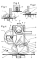
Die Erfindung wird anhand der Zeichnungen beispielsweise näher beschrieben. Die Fig. 1 bis 3 zeigen die starren, mechanisch ortslagebestimmten Halteleisten für magnetisch angepreßte Rollrakeln. Fig.4 zeigt ein Ausführungsbeispiel der Erfindung. Fig.5 zeigt ein anderes Ausführungsbeispiel. Die Fig. 6 und 7 zeigen eine Rakelprofilleiste in zwei verschiedenen Stellungen. Fig.8 und 9 sind Rakelleisten mit einer elastischen Rakelklinge bzw. einem druckelastischen Rakelprofil. Fig.10 zeigt eine abgeänderte Einrichtung gemäß der Erfindung und die Fig. 11 und 12 zeigen weitere Einzelheiten.The invention is described in more detail, for example, with reference to the drawings. 1 to 3 show the rigid, mechanically location-specific holding strips for magnetically pressed doctor blades. 4 shows an embodiment of the invention. 5 shows another embodiment. 6 and 7 show a squeegee profile strip in two different positions. 8 and 9 are doctor blades with an elastic doctor blade or a pressure-elastic doctor profile. 10 shows a modified device according to the invention and FIGS. 11 and 12 show further details.
Drei der bekannten Magnetrakelgeräte mit Hilfsvorrichtungen sind in den Fig.1 bis 3 dargestellt. Fig.1 zeigt eine magnetisch angepreßte Rollrakel 1 mit einer Stützleiste 2, in Bewegungsrichtung 3 gesehen, hinter der Rolle 1 angeordnet, entweder die Rollrakel 1 oder den Farb- bzw. Pastenwulst oder beides abstützend.Three of the known magnetic doctor devices with auxiliary devices are shown in FIGS. 1 to 3. 1 shows a magnetically pressed
Fig.2 zeigt die sogenannte Farbstauleiste 4 bzw. Farbstau- und Dichtleiste, die, in Bewegungsrichtung 3 gesehen, im Bereich vor der Rollrakel 1 und der vor der Rolle befindlichen Farbe 22 bzw. Paste angeordnet ist, und die je nach Dimension und Ortslage (Entfernung zur Auftragungsebene von der Schablone 5 oder Warenbahn 6), den Auftragungsvorgang mitbeeinflußt.2 shows the so-called
Ein weiteres bekanntes Magnetrakelgerät gemäß Fig.3 zeigt eine Doppelrollenanordnung in einem Käfig 23.
Dieser bekannte Stand der Technik gemäß Fig. 1-3 ist mit zwei Nachteilen verbunden:
- 1. sind diese Geräte nur zweiteilig zu handhaben, was im Vergleich mit einteiligen Geräten den doppelten Handhabungsaufwand erfordert,
- 2. sind die Rakelrollen, je kleiner der Durchmesser und je größer die Länge (d.h. Arbeitsbreite), umso verbiegungsgefährdeter und daher umso schwieriger zu handhaben.
This known prior art according to Figures 1-3 is associated with two disadvantages:
- 1. these devices can only be handled in two parts, which requires twice the handling effort in comparison with one-piece devices,
- 2. The smaller the diameter and the greater the length (ie the working width), the more risk of bending and therefore the more difficult to handle.
Dieser Handhabungsnachteil wiegt so schwer, daß in der Praxis die meisten Anwender solcher Geräte keine Rollen geringeren Durchmessers als 10 mm verwenden, obwohl für manche Auftragungserfordernisse Rakelrollen mit 8 mm oder 6 mm Durchmesser - mitunter sogar 4 mm Durchmesser - technologisch richtig wären.
Dies veranlaßt manche Anwender, auf Rakelgeräte anderer Konstruktionen auszuweichen bzw. unterschiedliche Maschinen und Geräte anzuschaffen, was dann mit weiteren wirtschaftlichen und betriebsorganisatorischen Nachteilen verbunden ist.This handling disadvantage weighs so heavily that in practice most users of such devices do not use rolls of smaller diameters than 10 mm, although for some application requirements doctor rolls with 8 mm or 6 mm diameter - sometimes even 4 mm diameter - would be technologically correct.
This causes some users to switch to doctoring devices of other designs or to buy different machines and devices, which is then associated with further economic and organizational disadvantages.
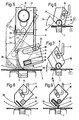
In Fig.4 ist gezeigt, daß die Ortslage der Rakelleiste bzw. der Rakelhalteleiste nur durch Magnetkraft bestimmt und gehalten wird. Das Rakelelement 8 besitzt hier eine Führung 9, in der ein Verschiebezapfen 10 gleitend angeordnet ist. Dieser Verschiebezapfen 10 wird von einem Verbindungselement 11 gehalten, das mit einem Tragholm 12 verbunden ist. Dieser Tragholm 12 hat einen trapezförmigen Querschnitt und trägt an seinen Enden runde Achszapfen 13. Diese Achszapfen 13 ruhen auf gerundeten Haltern 24.Durch Verdrehen des Tragholmes 12 in den Achszapfenlagerungen 24 wird das Verbindungselement 11 und damit der Verschiebezapfen 10 gehoben und gesenkt und entlang einer Kreisbahn 25 bewegt. Dies kippt das Rakelelement 8 um die Auflagekante 26. Eine zweite Stellung des Rakelelementes 8 ist strichliert dargestellt.In Fig. 4 it is shown that the position of the squeegee bar or the squeegee holding bar is determined and held only by magnetic force. The
Man kann leicht erkennen, daß dadurch auch der Winkel des Rakelelementes 8 zur Schablone 5 bzw. Warenbahn 6, die an den Magnettisch 7 angepreßt werden, geändert wird.Anstatt Verdrehen des Tragholmes 12 kann das Verschwenken des Rakelelementes 8 auch durch horizontales Verschieben in Richtung des Pfeiles 27 erfolgen.One can easily see that this also changes the angle of the
Zum Zuführen der aufzutragenden Substanz ist ein Trog 14 vorgesehen, der in eine Schiene 28 eingehängt werden kann, also einschiebbar ist. Der Trog kann um die Achse 15 gekippt werden oder entlang der strichliert gezeichneten Mulde 16 geführt werden. Bei diesem Verschwenken des Troges kann die aufzutragende Substanz 22 vor das Rakelelement 8 gebracht werden. Bei der relativen Lageänderung zwischen Verschiebezapfen 10 und Führung 9 wird, wie bereits erwähnt, das Rakelelement 8 verschwenkt und dadurch kann eine Arbeitsfläche 29 in Aktion treten, die einen Druck auf die aufzutragende Substanz 22 aufbringt.A
In Fig.5 ist eine ähnliche Ausführungsform der Erfindung wie in Fig.4 gezeigt, jedoch ist hier die gegen die Schablone 5 bzw. Warenbahn 6 gerichtete Fläche 29 gewölbt und an der Schwenkkante ist eine Rakelkante 18 angeformt. Das Rakelelement 8 besteht hier aus einem nicht magnetisierbarem Material, jedoch ist in einem Schlitz 21 eine magnetisierbare Leiste 20 eingebracht, so daß durch den Magnettisch 7 die Rakelkante 18 an die Schablone 5 bzw. Warenbahn 6 angepreßt werden kann. Anders als bei der Fig.4 ist hier die Substanzzuführung ausgebildet. Die Schwenkachse ist hier als Rohr 30 ausgebildet und in einen Profilkörper 31 eingeschoben. Im Profilkörper 31 befindet sich ein gegen das Rohr 30 geöffneter Hauptkanal 32, dessen Enden in je einen weiteren Kanal 33 einmünden, aus dem dann die aufzutragende Substanz über Bohrungen 34 austritt. Zusätzlich kann noch eine Prall- oder Umlenkleiste 35 vorhanden sein.5 shows a similar embodiment of the invention as shown in FIG. 4, but here the
In Fig.6 ist in einer Leiste 36 wiederum eine Führung 9 vorgesehen, in der der Verschiebezapfen 10 am Verbindungselement beweglich angeordnet ist. Das eigentliche Rakelelement ist hier eine Rolle 37, die vom Magnet 7 an die Warenbahn angepreßt wird. Die Fläche 29 dient wiederum dazu, einen Druck auf das aufzutragende Medium aufzubringen. Bei großem Winkel 38 zwischen der sogenannten Staufläche 29 der Leiste 36 und der Auftragungsfläche 6 bzw. der Schablone 5 erfolgt eine minimale Auftragung.In FIG. 6, a
In Fig.7 ist eine andere Arbeitsstellung dargestellt. Hier ist jedoch ein kleiner Winkel 39 zwischen der Staufläche 29 der Leiste 36 und der Auftragungsfläche 6 bzw. der Schablone gegeben, wodurch die maximale Auftragsleistung bewirkt wird.Another working position is shown in FIG. Here, however, there is a
In Fig.8 ist eine weitere Ausführungsform dargestellt, jedoch wird das Rakelelement hier durch eine Rakelklinge 40 gebildet und in der Leiste 36 befindet sich eine weitere Leiste 20 aus magnetisierbarem Material.A further embodiment is shown in FIG. 8, but here the doctor element is formed by a
Gemäß Fig.9 wird das Rakelelement durch einen druckelastischen Körper 41 gebildet und die magnetisierbare Masse 42 wird durch einen Rundstab gebildet, der an dem druckelastischen Körper 41 anliegt.According to FIG. 9, the squeegee element is formed by a pressure-
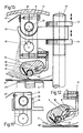
Die Ausbildung der Erfindung gemäß Fig.10 ist ähnlich jener der Fig.4 und 5. Durch Verdrehen der rohrförmigen Achse 30 mit dem Profilkörper 31, der zweiteilig daran angeklemmt ist und z.B. durch Schrauben 43 zusammengehalten ist oder durch Betätigen einer Stellmutter 44 auf einer Gewindestange 45, kann der Halter 24 höhenverstellt werden. Für den Farbaustritt ist eine Nut 46 vorhanden, wobei der Farbaustritt partiell oder durchgehend horizontal oder auch schräg nach unten gerichtet sein kann. Die Höhenverstellung kann auch elektromotorisch mittels der Gewindestange 45 erfolgen. Beim Ausbau der Einrichtung steht diese am Kopf und der Profilkörper 31 liegt auf einer Lagerschale 48 auf und es ist eine Rinne 47 vorgesehen, in die die restliche Farbe läuft und so leicht entfernt werden kann.The design of the invention according to FIG. 10 is similar to that of FIGS. 4 and 5. By rotating the
Fig.11 zeigt eine rechteckig ausgebildete Halterung 24 mit einem ebensolchen Profilkörper 31. Eine derartige Ausführungsform kann verwendet werden, wenn auf die Möglichkeit des Verschwenkens verzichtet wird.11 shows a
Fig.12 zeigt noch einmal den unteren Teil der Fig.10 in unterschiedlichen Winkel lagen (einmal voll ausgezogen, einmal strichliert), die durch die unterschiedliche Höhenposition des Verschiebezapfens 10 am Verbindungselement 11 gegeben ist.FIG. 12 again shows the lower part of FIG. 10 at different angles (once fully extended, once with dashed lines), which is given by the different height position of the
Die erfindungsgemäße Einrichtung kann in den beiden Ausführungsvarianten
- a) Farbzuführung von Hand aus bewerkstelligt oder
- b) Farbzuführung erfolgend mittels Pumpe, Rohrleitung, Verteilungseinrichtung und gegebenenfalls Steuerungsautomatik, wie folgt,in der Praxis angewendet werden.
- a) Color feed done by hand or
- b) Ink supply using a pump, pipeline, distribution device and, if necessary, automatic control, as follows, can be used in practice.
Die Ausführungsvariante (a) ist besonders wirtschaftlich anwendbar in Musterungs- und Kleinproduktionsmaschinen, die Ausführungsvariante (b) ist für Großproduktionsmaschinen zu bevorzugen. Darüberhinaus kann aber die Ausführungsvariante (a) auch bei Großproduktionen Verwendung finden,und zwar vorteilhafterweise in Verbindung mit solchen Schablonen, die nur sehr kleine Musterdetails drucken und, dadurch bedingt, einen sehr geringen Verbrauch an Druckfarbe bzw. Auftragungssubstanz haben.The design variant (a) is particularly economically applicable in sample and small production machines, the design variant (b) is preferred for large production machines. In addition, variant (a) can also be used in large-scale productions, advantageously in connection with stencils that print only very small sample details and, as a result, have a very low consumption of printing ink or application substance.
Es können also z.B. in einer Großproduktionsmaschine mit z.B. zehn Rundschablonenauftragungsstationen fünf mit der Ausführungsvariante (a) und die anderen fünf mit der Auftragungsvariante (b) bestückt werden.So e.g. in a large production machine with e.g. ten circular template application stations, five with the design variant (a) and the other five with the application variant (b).
Einer der wichtigsten Vorteile der erfindungsgemäßen Einrichtung besteht darin, daß die Rakelgeräte der vorbeschriebenen Ausführungsvarianten (a) und (b) die genau gleiche Auftragungscharakteristik haben und auch gleichartig einstellbar sind, so daß nicht nur jede Ausführungsvariante (a) und (b) in sich mit reproduzierbaren Auftragungsergebnissen einstellbar ist, sondern daß es auch möglich ist, Auftragungswerte, die in der Musterung mit Geräten der Ausführungsvariante (a) erzielt wurden, auf die Geräte der Ausführungsvariante (b) zu übertragen und mit dieser produktionsmäßig reproduzieren zu können.One of the most important advantages of the device according to the invention is that the doctor devices of the above-described embodiment variants (a) and (b) have the exact same application characteristics and can also be set in the same way, so that not only each embodiment variant (a) and (b) is in itself reproducible application results can be set, but that it is also possible to transfer application values that were achieved in the sample with devices of the embodiment variant (a) to the devices of the embodiment variant (b) and to be able to reproduce them in terms of production.
Durch vorbeschriebene Vorteile hat die vorliegende Erfindung auch in wirtschaftlicher Hinsicht eine große Bedeutung.Because of the advantages described above, the present invention is also of great economic importance.
Ergänzend sei noch gesagt, daß die Rakelgeräte samt den Winkelverstelleinrichtungen so installiert sind, daß händisch oder elektromechanisch erarbeitete Einstellwerte auch in den Computer einer mit erfindungsgemäßen Rakeleinrichtungen ausgestatteten automatisierten Produktionsanlage eingegeben werden können. Auch dieser Vorteil ist von großer technischer und wirtschaftlicher Bedeutung.In addition, it should also be said that the doctor devices together with the angle adjustment devices are installed in such a way that manually or electromechanically developed setting values can also be entered into the computer of an automated production system equipped with doctor devices according to the invention. This advantage is also of great technical and economic importance.
In der Ausführungsform Rakelleiste bzw. Rakelhalteleiste mit einer Rakelrolle als Rakelelement bestückt, erweist sich als vorteilhaft, die Oberfläche der Rakelrolle mit einer Struktur zu versehen.In the embodiment of the squeegee strip or squeegee holding strip equipped with a squeegee roller as the squeegee element, it has proven advantageous to provide the surface of the squeegee roller with a structure.
Eine in einer gleitlagerähnlichen Führung durchgehend gelagerte Rakelrolle mit einer strukturierten Oberfläche auszubilden, erscheint nahezu widersinnig und gegen die Regeln der Maschinenbautechnik verstoßend.Designing a doctor blade roller with a structured surface that is continuously supported in a slide bearing-like guide seems almost absurd and contravenes the rules of mechanical engineering.
Durch Versuche wurde aber bewiesen, daß bei optimaler Dimensionierung der Durchmesser bzw. der Durchmesserverhältnisse und zueinander passender Materialpaarung, Ausführungsvarianten dieser Art funktionsfähig sind und daß sich mit diesen Ausführungsvarianten überraschenderweise einige vorteilhafte Nutzungseffekte erzielen lassen; so z.B. bessere Haftung der Druckfarbe bzw. der aufzutragenden Substanz an der Rakelrolle und, dadurch bedingt, Mitnahme einer größeren Substanzmenge in das auftragungswirksame Anliegebereich; ebenso bewirkt die Strukturierung der Rollenoberfläche auch die Vergrößerung der Mitnahmefähigkeit der nach erfolgter Auftragung an der Rolle verbleibenden Spuren von Auftragungssubstanz und deren Mitnahme durch das zwischen Rollenoberfläche und gleitlagerähnlicher Führung bestehende Spalt- bzw. Berührungsbereich.However, tests have shown that, with optimal dimensioning, the diameter or the diameter ratio and each other suitable material pairing, design variants of this type are functional and that surprisingly some advantageous usage effects can be achieved with these design variants; for example, better adhesion of the printing ink or the substance to be applied to the doctor roller and, as a result, taking a larger quantity of substance into the application-effective area; Likewise, the structuring of the roller surface also increases the ability to take along the traces of application substance remaining on the roller after application and carry them away through the gap or contact area existing between roller surface and slide bearing-like guide.
Zusammenfassend sei gesagt, daß durch diese an sich ungewöhnliche, zusätzliche erfindungskennzeichnende Maßnahme sowohl eine Verbesserung der Auftragungsleistung als auch eine Vergrößerung der Betriebssicherheit bewirkt wird.In summary, it should be said that this unusual additional measure, which is characteristic of the invention, brings about both an improvement in the application performance and an increase in operational reliability.
Die Erfindung ist auf die dargestellten Beispiele nicht beschränkt, insbesondere ist es möglich, das Rakelelement nicht durch eine Schiebegelenkverbindung zu verstellen,sondern es z.B. getrennt einer Translation bzw. einer Drehung zu unterwerfen oder überhaupt nur eine Änderung der Ortslage vorzunehmen. Der Schutzbereich des Patents wird durch den Inhalt der Patentansprüche bestimmt.The invention is not limited to the examples shown, in particular it is possible not to adjust the squeegee element by means of a sliding joint connection, but rather to e.g. subject separately to a translation or a rotation or to change the location at all. The scope of protection of the patent is determined by the content of the claims.
Claims (23)
- An applicator device for applying patterns or coatings to, or the dyeing of, webs of fabric, for short lengths and/or for large-scale production, comprising a profiled strip (8, 36) which is constructed as or which holds an applicator element (37, 40, 41), the applicator element being pressable magnetically against the fabric web or against a stencil in contact with the fabric web, and comprising a support member connected pivotally to the profiled strip (8, 36) via a connecting element (11), the position of the profiled strip being variable by pivoting of the support member (12) about its longitudinal axis and/or by moving the support member at right angles to its longitudinal axis, characterised in that the pivotal connection between the support member and the profiled strip is a sliding joint connection (9, 10), and as a result of the pivoting and/or movement of the support member the profiled strip is pivoted about the line (18, 26) of contact of the applicator element on the fabric web or stencil or, in the case of a profiled strip movably holding a roller type applicator, the profiled strip is pivoted about the axis of the roller applicator and hence its angular position with respect to the application plane (6) is varied, the position of the contact line remaining unchanged for a given magnetic force.
- A device according to claim 1, characterised in that the applicator element or the profiled strip (8, 36, 40, 41) holding the applicator element is pivotable about the contact line (18, 26) or a pivot axis in the immediate vicinity of said line by a change of location of the sliding joint connection.
- A device according to claim 1 or 2, characterised in that the location of the sliding joint connection is variable with respect to the application plane.
- A device according to any one of the preceding claims, characterised in that the distance between the support member (12) and the application element is variable.
- A device according to claim 3, characterised in that the sliding joint connection is movable parallel to the application plane.
- A device according to claim 4, characterised in that the maximum distance between the support member and the applicator element or the profiled strip holding the applicator element is determined by the length of the connecting element (11).
- A device according to any one of the preceding claims, characterised in that the support member is rotatable about its axis.
- A device according to any one of the preceding claims, characterised in that the support member is movable with respect to the application plane.
- A device according to any one of the preceding claims, characterised in that the applicator element or the profiled strip holding the applicator element is formed at least partially from magnetisable material and by the pressing thereof is also held magnetically in the location, i.e. as considered longitudinally.
- A device according to any one of the preceding claims, characterised in that the applicator element, preferably an applicator roller, is structured on the surface.
- A device according to any one of claims 1 to 9, characterised in that the applicator element consists of a strip having a profiled edge.
- A device according to any one of claims 1 to 9, characterised in that the applicator element consists of a spreader profiled bar, having a circular cross-section if required.
- A device according to any one of claims 1 to 9, characterised in that the applicator element is formed from a flexurally elastic applicator blade of metal or plastic.
- A device according to any one of claims 1 to 9, characterised in that the applicator element is formed by a compression-resilient flexurally elastic applicator strip, e.g. of rubber or plastic.
- A device according to any one of the preceding claims 1 to 9, characterised in that the applicator element is an applicator roller, which is disposed in a recess in the profiled strip holding the applicator element, said recess being similar to a plain bearing.
- A device according to any one of the preceding claims, characterised in that the profiled strip consists at least partially of a flexible material or a material having low inherent rigidity.
- A device according to any one of the preceding claims, characterised in that the applicator element consists of a non-magnetisable material and if required is provided with a bar consisting of magnetisable material, in a fragmentary arrangement if required.
- A device according to any one of the preceding claims, characterised in that the substance supply is provided by a supply device in the form of a bath or trough fixed to the support member preferably so as to be capable of being pushed in or pivoted.
- A device according to claim 18, characterised in that the supply device is pivotable about a spindle.
- A device according to any one of the preceding claims 1 to 17, characterised in that the support member spindle is constructed as a substance supply tube and has exit apertures distributed over the length.
- A device according to any one of claims 18 to 20, characterised in that the supply device projects beyond a cylinder stencil on at least one side and allows refiling during operation.
- A device according to any one of the preceding claims, characterised in that the applicator element and the support member are adjustable at an angle to one another in at least one direction.
- A device according to any one of the preceding claims, characterised in that the applicator element has a flat or curved retaining surface.
Applications Claiming Priority (3)
| Application Number | Priority Date | Filing Date | Title |
|---|---|---|---|
| AT1943/89 | 1989-08-16 | ||
| AT1943/89A AT392745B (en) | 1989-08-16 | 1989-08-16 | DEVICE AND METHOD FOR SAMPLE AND / OR FULL AREA APPLICATION PROCESSES ON SHORT AND ANY LONG TRACKS |
| PCT/AT1990/000077 WO1991002650A1 (en) | 1989-08-16 | 1990-07-31 | Device and process for carrying out application operations |
Publications (2)
| Publication Number | Publication Date |
|---|---|
| EP0438552A1 EP0438552A1 (en) | 1991-07-31 |
| EP0438552B1 true EP0438552B1 (en) | 1995-10-18 |
Family
ID=3524389
Family Applications (1)
| Application Number | Title | Priority Date | Filing Date |
|---|---|---|---|
| EP90910481A Expired - Lifetime EP0438552B1 (en) | 1989-08-16 | 1990-07-31 | Device and process for carrying out application operations |
Country Status (8)
| Country | Link |
|---|---|
| US (1) | US5239922A (en) |
| EP (1) | EP0438552B1 (en) |
| JP (1) | JP2607311B2 (en) |
| AT (2) | AT392745B (en) |
| BR (1) | BR9006883A (en) |
| DE (1) | DE59009798D1 (en) |
| ES (1) | ES2080828T3 (en) |
| WO (1) | WO1991002650A1 (en) |
Families Citing this family (14)
| Publication number | Priority date | Publication date | Assignee | Title |
|---|---|---|---|---|
| DE9112032U1 (en) * | 1991-09-23 | 1993-01-28 | Zimmer, Johannes, Klagenfurt, Kärnten | Squeegee device |
| DE9112033U1 (en) * | 1991-09-23 | 1993-01-28 | Zimmer, Johannes, Klagenfurt, Kärnten | Squeegee device |
| FR2700731B1 (en) * | 1993-01-22 | 1995-04-07 | Dubuit Mach | Scraping head, in particular for a silk screen printing machine. |
| US5510510A (en) * | 1994-05-10 | 1996-04-23 | Bristol-Meyers Squibb Company | Inhibitors of farnesyl protein transferase |
| DE29517098U1 (en) * | 1995-10-17 | 1997-02-13 | Zimmer, Johannes, Klagenfurt | Application device |
| DE29517099U1 (en) * | 1995-10-17 | 1997-02-27 | Zimmer, Johannes, Klagenfurt | Application device |
| US6217707B1 (en) | 1996-12-31 | 2001-04-17 | Kimberly-Clark Worldwide, Inc. | Controlled coverage additive application |
| US6231719B1 (en) | 1996-12-31 | 2001-05-15 | Kimberly-Clark Worldwide, Inc. | Uncreped throughdried tissue with controlled coverage additive |
| JP3798193B2 (en) * | 1999-08-02 | 2006-07-19 | 理想科学工業株式会社 | Stencil printing machine |
| DE10358221A1 (en) * | 2003-12-12 | 2005-07-07 | Voith Paper Patent Gmbh | doctor device |
| DE102015208919A1 (en) * | 2015-05-13 | 2016-11-17 | Koenig & Bauer Ag | Doctor device, printing unit and method for operating a squeegee device |
| CN107366115B (en) * | 2017-06-22 | 2023-10-31 | 杭州三拓科技有限公司 | Dyestuff material device |
| CN112918084A (en) * | 2021-01-22 | 2021-06-08 | 温州旺信贸易有限公司 | Screen printing ink scraping device convenient for adjusting ink scraping angle and ink return amount |
| CN119186921B (en) * | 2024-11-26 | 2025-02-25 | 汕头市庆达机电设备有限公司 | A coating head with multiple coating methods |
Family Cites Families (5)
| Publication number | Priority date | Publication date | Assignee | Title |
|---|---|---|---|---|
| US3974766A (en) * | 1973-09-10 | 1976-08-17 | Peter Zimmer | Process for imprinting spaced-apart web sections with a composite pattern |
| AT376399B (en) * | 1981-12-07 | 1984-11-12 | Zimmer Johannes | Squeegee device |
| EP0126723A3 (en) * | 1983-05-18 | 1986-10-29 | Svecia Silkscreen Maskiner AB | Method and arrangement for positioning a second pattern origination from a pattern formed on a stencil in relation to a material intended for the pattern |
| JPH03501823A (en) * | 1987-10-10 | 1991-04-25 | ツインマー,ヨハネス | Coating device |
| EP0311728B1 (en) * | 1987-10-10 | 1993-03-10 | Johannes Zimmer | Doctoring device |
-
1989
- 1989-08-16 AT AT1943/89A patent/AT392745B/en not_active IP Right Cessation
-
1990
- 1990-07-31 US US07/659,285 patent/US5239922A/en not_active Expired - Fee Related
- 1990-07-31 JP JP2510625A patent/JP2607311B2/en not_active Expired - Lifetime
- 1990-07-31 BR BR909006883A patent/BR9006883A/en not_active IP Right Cessation
- 1990-07-31 WO PCT/AT1990/000077 patent/WO1991002650A1/en not_active Ceased
- 1990-07-31 ES ES90910481T patent/ES2080828T3/en not_active Expired - Lifetime
- 1990-07-31 EP EP90910481A patent/EP0438552B1/en not_active Expired - Lifetime
- 1990-07-31 DE DE59009798T patent/DE59009798D1/en not_active Expired - Fee Related
- 1990-07-31 AT AT90910481T patent/ATE129187T1/en not_active IP Right Cessation
Also Published As
| Publication number | Publication date |
|---|---|
| EP0438552A1 (en) | 1991-07-31 |
| JPH04506940A (en) | 1992-12-03 |
| BR9006883A (en) | 1991-11-05 |
| JP2607311B2 (en) | 1997-05-07 |
| ATE129187T1 (en) | 1995-11-15 |
| ATA194389A (en) | 1990-11-15 |
| WO1991002650A1 (en) | 1991-03-07 |
| US5239922A (en) | 1993-08-31 |
| DE59009798D1 (en) | 1995-11-23 |
| ES2080828T3 (en) | 1996-02-16 |
| AT392745B (en) | 1991-05-27 |
Similar Documents
| Publication | Publication Date | Title |
|---|---|---|
| EP0438552B1 (en) | Device and process for carrying out application operations | |
| DE19718113C2 (en) | Doctor device for screen printing | |
| EP0311728B1 (en) | Doctoring device | |
| DE2950025A1 (en) | WITH WATER OR A MIXTURE OF WATER AND ALCOHOL WET DAMPING UNIT FOR OFFSET PRINTING MACHINES | |
| DE3689176T2 (en) | Doctor blade device for a coating apparatus. | |
| CH652943A5 (en) | DEVICE FOR COATING PAPER FILMS. | |
| EP0408704B1 (en) | Arrangement for applying substances to a web of material | |
| CH668922A5 (en) | METHOD AND DEVICE FOR COATING A MOVING MATERIAL. | |
| EP0602431A1 (en) | Ductor blade arrangement | |
| DE4444779B4 (en) | Device for applying a liquid or pasty medium to a moving material web, in particular of paper or cardboard | |
| EP0149841A2 (en) | Method and means for inking the plate of a forme cilinder of a rotary printing machine | |
| EP0235204B1 (en) | Device for applying and dosing of fluid media to a web or a cylinder | |
| EP0311730B1 (en) | Squeegee | |
| DE69119650T2 (en) | Etching material coating device | |
| DE2804801A1 (en) | Rubber cloth washing equipment for printing press - has washing fluid delivered to porous sintered strip bearing against cloth | |
| EP0135618A2 (en) | Screen printer | |
| DE4213669A1 (en) | Device for positioning a doctor bar on an ink-donating roller of a web-fed rotary printing press | |
| DE2754663A1 (en) | DEVICE FOR APPLYING MEDIA INTO A SUBSTRATE | |
| DE29716541U1 (en) | Device for applying liquids to a substrate | |
| DE102006008002A1 (en) | Inking unit, and method for the sujetspezifischen vote a configuration state of the same | |
| DE69527024T2 (en) | Process and structure for monitoring the coating profile in coating devices based on an order with a short waiting time | |
| AT401480B (en) | SCRAPER FOR APPLICATION OR APPLY AND SCRATCH OR FOR THE DOSED APPLICATION OF FLOWABLE OR FLOWABLE SUBSTANCES | |
| EP0463142B1 (en) | Magnetically pressed doctor blade and doctor blade device, in particular round stencil (sieve cylinder) | |
| DE2903415C2 (en) | ||
| DE69808817T2 (en) | Squeegee with a fixed support |
Legal Events
| Date | Code | Title | Description |
|---|---|---|---|
| PUAI | Public reference made under article 153(3) epc to a published international application that has entered the european phase |
Free format text: ORIGINAL CODE: 0009012 |
|
| 17P | Request for examination filed |
Effective date: 19910409 |
|
| AK | Designated contracting states |
Kind code of ref document: A1 Designated state(s): AT CH DE ES FR GB IT LI NL |
|
| 17Q | First examination report despatched |
Effective date: 19930211 |
|
| GRAA | (expected) grant |
Free format text: ORIGINAL CODE: 0009210 |
|
| AK | Designated contracting states |
Kind code of ref document: B1 Designated state(s): AT CH DE ES FR GB IT LI NL |
|
| PG25 | Lapsed in a contracting state [announced via postgrant information from national office to epo] |
Ref country code: GB Effective date: 19951018 Ref country code: FR Effective date: 19951018 |
|
| REF | Corresponds to: |
Ref document number: 129187 Country of ref document: AT Date of ref document: 19951115 Kind code of ref document: T |
|
| REF | Corresponds to: |
Ref document number: 59009798 Country of ref document: DE Date of ref document: 19951123 |
|
| ITF | It: translation for a ep patent filed | ||
| REG | Reference to a national code |
Ref country code: ES Ref legal event code: FG2A Ref document number: 2080828 Country of ref document: ES Kind code of ref document: T3 |
|
| EN | Fr: translation not filed | ||
| GBV | Gb: ep patent (uk) treated as always having been void in accordance with gb section 77(7)/1977 [no translation filed] |
Effective date: 19951018 |
|
| PLBE | No opposition filed within time limit |
Free format text: ORIGINAL CODE: 0009261 |
|
| STAA | Information on the status of an ep patent application or granted ep patent |
Free format text: STATUS: NO OPPOSITION FILED WITHIN TIME LIMIT |
|
| 26N | No opposition filed | ||
| PGFP | Annual fee paid to national office [announced via postgrant information from national office to epo] |
Ref country code: CH Payment date: 19990709 Year of fee payment: 10 |
|
| PG25 | Lapsed in a contracting state [announced via postgrant information from national office to epo] |
Ref country code: LI Free format text: LAPSE BECAUSE OF NON-PAYMENT OF DUE FEES Effective date: 20000731 Ref country code: CH Free format text: LAPSE BECAUSE OF NON-PAYMENT OF DUE FEES Effective date: 20000731 |
|
| REG | Reference to a national code |
Ref country code: CH Ref legal event code: PL |
|
| PGFP | Annual fee paid to national office [announced via postgrant information from national office to epo] |
Ref country code: AT Payment date: 20040722 Year of fee payment: 15 |
|
| PGFP | Annual fee paid to national office [announced via postgrant information from national office to epo] |
Ref country code: ES Payment date: 20040726 Year of fee payment: 15 |
|
| PGFP | Annual fee paid to national office [announced via postgrant information from national office to epo] |
Ref country code: DE Payment date: 20040729 Year of fee payment: 15 |
|
| PGFP | Annual fee paid to national office [announced via postgrant information from national office to epo] |
Ref country code: NL Payment date: 20040731 Year of fee payment: 15 |
|
| PG25 | Lapsed in a contracting state [announced via postgrant information from national office to epo] |
Ref country code: IT Free format text: LAPSE BECAUSE OF NON-PAYMENT OF DUE FEES;WARNING: LAPSES OF ITALIAN PATENTS WITH EFFECTIVE DATE BEFORE 2007 MAY HAVE OCCURRED AT ANY TIME BEFORE 2007. THE CORRECT EFFECTIVE DATE MAY BE DIFFERENT FROM THE ONE RECORDED. Effective date: 20050731 Ref country code: AT Free format text: LAPSE BECAUSE OF NON-PAYMENT OF DUE FEES Effective date: 20050731 |
|
| PG25 | Lapsed in a contracting state [announced via postgrant information from national office to epo] |
Ref country code: ES Free format text: LAPSE BECAUSE OF NON-PAYMENT OF DUE FEES Effective date: 20050801 |
|
| PG25 | Lapsed in a contracting state [announced via postgrant information from national office to epo] |
Ref country code: NL Free format text: LAPSE BECAUSE OF NON-PAYMENT OF DUE FEES Effective date: 20060201 Ref country code: DE Free format text: LAPSE BECAUSE OF NON-PAYMENT OF DUE FEES Effective date: 20060201 |
|
| NLV4 | Nl: lapsed or anulled due to non-payment of the annual fee |
Effective date: 20060201 |
|
| REG | Reference to a national code |
Ref country code: ES Ref legal event code: FD2A Effective date: 20050801 |