EP0437733B1 - Vorrichtung zum Reinigen und Entleeren von Flüssigkeitsleitungen, insbesondere Getränkeleitungen in Zapfanlagen - Google Patents
Vorrichtung zum Reinigen und Entleeren von Flüssigkeitsleitungen, insbesondere Getränkeleitungen in Zapfanlagen Download PDFInfo
- Publication number
- EP0437733B1 EP0437733B1 EP90123908A EP90123908A EP0437733B1 EP 0437733 B1 EP0437733 B1 EP 0437733B1 EP 90123908 A EP90123908 A EP 90123908A EP 90123908 A EP90123908 A EP 90123908A EP 0437733 B1 EP0437733 B1 EP 0437733B1
- Authority
- EP
- European Patent Office
- Prior art keywords
- valve
- connection
- cleaning
- beverage
- valve housing
- Prior art date
- Legal status (The legal status is an assumption and is not a legal conclusion. Google has not performed a legal analysis and makes no representation as to the accuracy of the status listed.)
- Expired - Lifetime
Links
- 238000004140 cleaning Methods 0.000 title claims abstract description 53
- 235000013361 beverage Nutrition 0.000 title claims abstract description 50
- 238000009434 installation Methods 0.000 title claims abstract 3
- 238000010079 rubber tapping Methods 0.000 title claims description 3
- 239000012530 fluid Substances 0.000 title 1
- XLYOFNOQVPJJNP-UHFFFAOYSA-N water Substances O XLYOFNOQVPJJNP-UHFFFAOYSA-N 0.000 claims abstract description 30
- 239000007788 liquid Substances 0.000 claims abstract description 5
- 238000007789 sealing Methods 0.000 claims description 4
- 230000003213 activating effect Effects 0.000 claims 1
- 235000013405 beer Nutrition 0.000 description 5
- 239000008267 milk Substances 0.000 description 3
- 210000004080 milk Anatomy 0.000 description 3
- 235000013336 milk Nutrition 0.000 description 3
- 238000000034 method Methods 0.000 description 2
- 238000010276 construction Methods 0.000 description 1
- 238000013461 design Methods 0.000 description 1
- 238000006073 displacement reaction Methods 0.000 description 1
- 235000013305 food Nutrition 0.000 description 1
- 230000005484 gravity Effects 0.000 description 1
- 238000012994 industrial processing Methods 0.000 description 1
- 238000009776 industrial production Methods 0.000 description 1
- 235000021056 liquid food Nutrition 0.000 description 1
- 239000002184 metal Substances 0.000 description 1
- 238000012986 modification Methods 0.000 description 1
- 230000004048 modification Effects 0.000 description 1
- 230000000630 rising effect Effects 0.000 description 1
- 238000012549 training Methods 0.000 description 1
- 230000001960 triggered effect Effects 0.000 description 1
Images


Classifications
-
- B—PERFORMING OPERATIONS; TRANSPORTING
- B67—OPENING, CLOSING OR CLEANING BOTTLES, JARS OR SIMILAR CONTAINERS; LIQUID HANDLING
- B67D—DISPENSING, DELIVERING OR TRANSFERRING LIQUIDS, NOT OTHERWISE PROVIDED FOR
- B67D1/00—Apparatus or devices for dispensing beverages on draught
- B67D1/07—Cleaning beverage-dispensing apparatus
-
- B—PERFORMING OPERATIONS; TRANSPORTING
- B08—CLEANING
- B08B—CLEANING IN GENERAL; PREVENTION OF FOULING IN GENERAL
- B08B9/00—Cleaning hollow articles by methods or apparatus specially adapted thereto
- B08B9/02—Cleaning pipes or tubes or systems of pipes or tubes
- B08B9/027—Cleaning the internal surfaces; Removal of blockages
- B08B9/04—Cleaning the internal surfaces; Removal of blockages using cleaning devices introduced into and moved along the pipes
- B08B9/053—Cleaning the internal surfaces; Removal of blockages using cleaning devices introduced into and moved along the pipes moved along the pipes by a fluid, e.g. by fluid pressure or by suction
- B08B9/055—Cleaning the internal surfaces; Removal of blockages using cleaning devices introduced into and moved along the pipes moved along the pipes by a fluid, e.g. by fluid pressure or by suction the cleaning devices conforming to, or being conformable to, substantially the same cross-section of the pipes, e.g. pigs or moles
-
- B—PERFORMING OPERATIONS; TRANSPORTING
- B08—CLEANING
- B08B—CLEANING IN GENERAL; PREVENTION OF FOULING IN GENERAL
- B08B9/00—Cleaning hollow articles by methods or apparatus specially adapted thereto
- B08B9/02—Cleaning pipes or tubes or systems of pipes or tubes
- B08B9/027—Cleaning the internal surfaces; Removal of blockages
- B08B9/04—Cleaning the internal surfaces; Removal of blockages using cleaning devices introduced into and moved along the pipes
- B08B9/053—Cleaning the internal surfaces; Removal of blockages using cleaning devices introduced into and moved along the pipes moved along the pipes by a fluid, e.g. by fluid pressure or by suction
- B08B9/057—Cleaning the internal surfaces; Removal of blockages using cleaning devices introduced into and moved along the pipes moved along the pipes by a fluid, e.g. by fluid pressure or by suction the cleaning devices being entrained discrete elements, e.g. balls, grinding elements, brushes
-
- F—MECHANICAL ENGINEERING; LIGHTING; HEATING; WEAPONS; BLASTING
- F16—ENGINEERING ELEMENTS AND UNITS; GENERAL MEASURES FOR PRODUCING AND MAINTAINING EFFECTIVE FUNCTIONING OF MACHINES OR INSTALLATIONS; THERMAL INSULATION IN GENERAL
- F16D—COUPLINGS FOR TRANSMITTING ROTATION; CLUTCHES; BRAKES
- F16D3/00—Yielding couplings, i.e. with means permitting movement between the connected parts during the drive
- F16D3/02—Yielding couplings, i.e. with means permitting movement between the connected parts during the drive adapted to specific functions
- F16D3/08—Couplings for intersecting shafts, provided with intermediate bars bent in an angle corresponding with the angle of intersection
Definitions
- the invention relates to a device for cleaning and emptying liquid lines, in particular beverage lines in dispensing systems, with a slide or rotary slide valve, in which the valve slide is movable in a recess in a valve housing in such a way that at least one transverse bore in the valve slide in connection with a connecting piece for the Inlet of the beverage can be brought, and with a cylindrical magazine for elastic, spherical cleaning bodies and a connecting piece for the water supply.
- the invention is based on a cleaning device as described in DE-OS 35 04 636.
- a threaded connection is provided for the supply and discharge of the water.
- a magazine for spherical, elastic cleaning bodies is attached to the upper wall of the valve housing.
- the valve slide is constructed in two parts and has a switch body which can be rotated about its longitudinal axis and which is provided with a central central bore extending into an end ball.
- the beverage line leading to the barrel and the tap leading to the tap are to be cleaned alternately, with no disturbance of the beverage being caused in the operating or dispensing position.
- the known device is relatively complicated and can only be actuated on the spot by means of a slide and rotary switch lever.
- the cleaning of the beverage line leading to the barrel and the tap leading to the tap can only be carried out alternately.
- the present invention has for its object to simplify the previously known cleaning device with regard to the structure and the operational sequence between tap operation and cleaning operation.
- the cylindrical magazine for the elastic, spherical cleaning body and the connecting piece leading to a flexible beverage line for serving are arranged directly on the upper side of the valve slide which can be actuated by a suitable drive device and each with a corresponding bore are displaceable, the threaded connection for the cleaning water supply and the connection for the beverage supply in the lower part of the valve housing being arranged at a distance from one another, such that in the one end position of the slide in the operating state the two through-holes cover the two connecting pieces in the lower part of the valve body Be brought valve housing and in the cleaning or emptying state, the connection for the beverage supply closed and the beverage line leading to the bar with the threaded connection for the cleaning water drove is connected.
- the threaded connection and the connection for the beverage supply in the lower part of the valve housing have the same distance from one another as the two through holes in the valve slide.
- the threaded connection and the connection for the beverage supply in the lower part of the valve housing are at a greater distance from one another than the two through holes in the valve slide.
- a space for receiving a spherical, elastic cleaning body is provided in the upper part of the threaded connection for the cleaning water supply, which falls from the tubular magazine in the position of the operating state in this space and in the position of the cleaning state of the water column through the beverage line leading to the bar is pressed.
- the main advantage is achieved that with a compared to the device known from DE-OS 35 04 636 much simpler slide or rotary slide valve, the cleaning and emptying process can be carried out in the beverage line leading to the bar. Due to the particularly simple construction, it is also possible to place the device according to the invention directly on the beverage container, for example a beer keg, so that a special feed line can be omitted between the beer keg and the device according to the invention.
- Another advantage of the device according to the invention is that the cleaning leading to the bar Beverage line can be carried out without loss of beverage, since the beverage in the line is still fully usable when the cleaning process is initiated until the cleaning body appears.
- the drive device for actuating the valve slide consists of an optionally remote-controlled pressure piston, which is acted upon by a CO2 pressure bottle, which is required, for example, when tapping beer.
- the slide for longitudinal movement in the valve housing can have a cross-sectional profile, for example a dovetail profile, in order to ensure guidance in a corresponding groove within the valve housing.
- the connecting pieces in the lower part of the valve housing can be provided with spring-loaded, cylindrical inserts for sealing against the lower surface of the slide.
- the entire device according to the invention according to claim 8 can be provided with a connecting piece for the beverage supply, which has an attachment for direct placement on a beverage keg.
- the device according to the invention consists of a valve housing 1 designed as a block, in which there is a T-shaped groove 2 for receiving a correspondingly designed, T-shaped valve slide 3.
- connection 4 is provided for the beverage supply, which is directly on an extension 5 of a beverage container 6, for example a beer keg, is placed.
- a connection 7 is provided for the CO2, which is supplied by a CO2 bottle, not shown.
- a cylindrical magazine 9 is arranged above a bore 8 in the spool 3, in which there are elastic, spherical cleaning bodies 10, for example small balls or sponges.
- a connecting piece 12 is arranged over a further bore 11 in the valve slide 3, which is connected to a flexible beverage line 13, which leads to the bar.
- a threaded connection 14 for the supply line 15 for the cleaning water is also provided in addition to the connection 4 for the beverage supply.
- the threaded connection 14 for the supply of cleaning water and the connection 4 for the supply of drinks in the lower part of the valve housing 1 have the same distance from one another as the two through holes 8 and 11 in the valve slide.
- a pressure piston arrangement 16 is also arranged in the valve housing 1, the connection 17 of which is connected to the CO2 bottle, not shown.
- the pressure piston can be triggered by a remote control device (not shown), so that the device can be operated from any location within a certain radius.
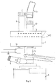
- Fig. 2 is in the upper part of the connecting piece 14 for the cleaning water supply Room 18 for receiving a spherical, elastic cleaning body 10 is provided, which falls from the tubular magazine 9 in the position of the operating state described below in this room.
- the connecting pieces 4 and 14 also have cylindrical inserts 21, 22 loaded by coil springs 19, 20, which press against the lower surface of the slide 3 for sealing.
- the magazine 9 is in correspondence with the water connection 14, so that a cleaning body 10 falls into the upper space 18 by gravity.
- the bore 11 is in line with the connection 4, so that, starting from the beverage container 6, the beverage is guided in the direction of arrow 24 through the flexible line 13 to the dispenser.
- FIGS. 4 and 5 The cleaning or emptying state is shown in FIGS. 4 and 5.
- the slide 3 is moved in the direction of the double arrow 25 to the left, so that the outlet of the magazine 9 is closed by the base of the valve housing 1. Furthermore, the connection 4 for the beverage supply is closed by the base 23 of the slide 3.
- connection piece 12 with the through hole 11 is in this position above the connection 14 for the water supply.
- the pressure of the water column pushes the cleaning body 10 upwards into the flexible line 13 and from there to the dispenser.
- the boundary between the rising column of water and the beverage column located in the line 13 forms the spherical, elastic cleaning body 10.
- the person operating the tap can therefore still use the beverage standing in the beverage line 13 until the cleaning body 10 emerges from the tap at the dispenser. If the remaining amount of beverage is predetermined, the person serving the drink knows exactly how much beverage can still be administered. As a result, the device according to the invention works without loss of drinks.
- FIG. 6 shows a section through another embodiment of the invention corresponding to FIG. 5.
- the slide 3 ' is dovetail-shaped and runs in a corresponding dovetail-shaped recess 2'.
- other forms of training of the slide are also possible. It is only essential that it is clearly guided in the valve housing 1.
- the slide is also possible to design the slide as a rotary slide valve, in which case the valve housing has a circular shape in which the corresponding connecting pieces are located.
- the device according to the invention is not only intended for a beverage dispensing system, for example a beer dispensing system, but rather can also be used in systems for other liquids and liquid foods, such as milk, milk products or the like.
- This application is intended in particular for the industrial production and processing of liquids and food, such as in milk centers, at beverage manufacturers, etc.
- FIGS. 7 to 9 show a modified embodiment the device according to the invention shown using a rotary slide valve.
- the rotary slide valve 26 is located there within a valve housing 28 which has a semicircular region 27.
- the bent connection piece 29 leads to the flexible beverage line for serving.
- the beverage inlet connector 4 and the connector 14 for the cleaning water supply are arranged in the lower part of the valve housing 28, with instead of the longitudinal movement of the slide 26 executing a rotary movement either to connect the connector 4 to the curved connector 29 or after a rotary movement, the connection for the To connect cleaning water supply together with the cleaning body 10 located therein to the connecting piece 29.
- two pressure connections 30, 31 are provided, behind which pressure pistons 32, 33 are arranged in suitable guides.
- the pressure pistons are connected to metal balls 34, which bear against a part 35 of the rotary valve 26. Depending on which pressure piston 32, 33 is pressurized, the part 35 is brought into the corresponding end position by the balls 34. This also triggers the previously described rotary movement of the connecting pieces 4, 14.
- a further change to the device according to the invention can consist in providing a switching valve in the water supply line to the water connection 14, which valve is blocked when the magazine 9 is located above the water connection 14. In this way, the magazine space can be kept free of pressurized water during the fall of the cleaning body 10 into the space 18.
Landscapes
- Engineering & Computer Science (AREA)
- Mechanical Engineering (AREA)
- General Engineering & Computer Science (AREA)
- Physics & Mathematics (AREA)
- Fluid Mechanics (AREA)
- Devices For Dispensing Beverages (AREA)
- Cleaning In General (AREA)
- Medicines That Contain Protein Lipid Enzymes And Other Medicines (AREA)
- Non-Alcoholic Beverages (AREA)
- Apparatus For Making Beverages (AREA)
Priority Applications (1)
| Application Number | Priority Date | Filing Date | Title |
|---|---|---|---|
| AT90123908T ATE92793T1 (de) | 1989-12-23 | 1990-12-12 | Vorrichtung zum reinigen und entleeren von fluessigkeitsleitungen, insbesondere getraenkeleitungen in zapfanlagen. |
Applications Claiming Priority (2)
| Application Number | Priority Date | Filing Date | Title |
|---|---|---|---|
| DE3942788 | 1989-12-23 | ||
| DE3942788A DE3942788A1 (de) | 1989-12-23 | 1989-12-23 | Vorrichtung zum reinigen und entleeren von fluessigkeitsleitungen, insbesondere getraenkeleitungen in zapfanlagen |
Publications (2)
| Publication Number | Publication Date |
|---|---|
| EP0437733A1 EP0437733A1 (de) | 1991-07-24 |
| EP0437733B1 true EP0437733B1 (de) | 1993-08-11 |
Family
ID=6396315
Family Applications (1)
| Application Number | Title | Priority Date | Filing Date |
|---|---|---|---|
| EP90123908A Expired - Lifetime EP0437733B1 (de) | 1989-12-23 | 1990-12-12 | Vorrichtung zum Reinigen und Entleeren von Flüssigkeitsleitungen, insbesondere Getränkeleitungen in Zapfanlagen |
Country Status (10)
| Country | Link |
|---|---|
| EP (1) | EP0437733B1 (cs) |
| JP (1) | JP2571990B2 (cs) |
| AT (1) | ATE92793T1 (cs) |
| AU (1) | AU6917691A (cs) |
| CA (1) | CA2071991A1 (cs) |
| CS (1) | CS656890A3 (cs) |
| DE (2) | DE3942788A1 (cs) |
| ES (1) | ES2045735T3 (cs) |
| PL (1) | PL288417A1 (cs) |
| WO (1) | WO1991009692A1 (cs) |
Families Citing this family (7)
| Publication number | Priority date | Publication date | Assignee | Title |
|---|---|---|---|---|
| DE9110219U1 (de) * | 1991-08-19 | 1991-10-24 | Till, Sascha, 7573 Sinzheim | Vorrichtung zur automatischen Entnahme von Schwammgummikugeln in Flüssigkeitsleitungen, insbesondere Getränkeleitungen in Zapfanlagen |
| DE9113488U1 (de) * | 1991-10-30 | 1992-02-06 | Till, Rudolf, 7573 Sinzheim | Vorrichtung zum Reinigen und Entleeren von Getränkeflüssigkeitsleitungen in Zapfanlagen |
| DE4221577C2 (de) * | 1992-07-01 | 1995-04-13 | Bersch Friedrich | Vorrichtung zur Reinigung von Rohrleitungen |
| AU4038493A (en) * | 1992-11-04 | 1994-05-24 | Kundo Systemtechnik Gmbh | Drink-retailing apparatus |
| US5535923A (en) * | 1993-01-25 | 1996-07-16 | Kirin Beer Kabushiki Kaisha | Washing apparatus for beverage pouring apparatus |
| DE19542840A1 (de) * | 1995-11-17 | 1997-05-22 | Kundo Systemtechnik Gmbh | Einrichtung zur Reinigung der zwischen einem Getränkebehälter und dem Zapfhahn einer Getränkezapfanlage verlaufenden Getränkeleitung |
| NL1032098C2 (nl) | 2006-06-30 | 2008-01-02 | Heineken Supply Chain Bv | Tapinrichting, drankcontainer, koppelingsinrichting en werkwijze met reinigingselement. |
Family Cites Families (7)
| Publication number | Priority date | Publication date | Assignee | Title |
|---|---|---|---|---|
| DE318557C (cs) * | ||||
| FR2030196A1 (cs) * | 1969-01-27 | 1970-10-30 | Ite Imperial Corp | |
| DE2943967A1 (de) * | 1979-10-31 | 1981-05-14 | Friedrich Wilh. Schwing Gmbh, 4690 Herne | Rohrleitungsarmatur mit einem in leitungen, die unter druck stehende dickstoffe, vorzugsweise beton foerdern, einbaubarem gehaeuse zum einwechseln eines wischers |
| DE2927324C3 (de) * | 1979-07-06 | 1994-09-15 | Schwing Gmbh F | Rohrleitungsarmatur mit einem in Leitungen, die unter Druck stehende Dickstoffe, vorzugsweise Beton fördern, einbaubaren Gehäuse zum Einwechseln eines Wischers |
| DE3322908A1 (de) * | 1983-06-25 | 1985-01-10 | Ewald 5403 Mülheim-Kärlich Wagner | Reinigungsvorrichtung fuer zapfanlagen |
| DE3504636A1 (de) * | 1985-02-11 | 1986-08-14 | Ewald 5403 Mülheim-Kärlich Wagner | Reinigungsvorrichtung fuer getraenkezapfanlagen |
| DE8708749U1 (de) * | 1987-06-24 | 1987-08-20 | Bergwerksverband Gmbh, 4300 Essen | Einrichtung zum Ein- und Ausschleusen von Rohrreinigungsmolchen |
-
1989
- 1989-12-23 DE DE3942788A patent/DE3942788A1/de not_active Withdrawn
-
1990
- 1990-12-12 EP EP90123908A patent/EP0437733B1/de not_active Expired - Lifetime
- 1990-12-12 DE DE9090123908T patent/DE59002315D1/de not_active Expired - Fee Related
- 1990-12-12 AT AT90123908T patent/ATE92793T1/de not_active IP Right Cessation
- 1990-12-12 ES ES90123908T patent/ES2045735T3/es not_active Expired - Lifetime
- 1990-12-21 AU AU69176/91A patent/AU6917691A/en not_active Abandoned
- 1990-12-21 WO PCT/DE1990/000993 patent/WO1991009692A1/de not_active Ceased
- 1990-12-21 PL PL28841790A patent/PL288417A1/xx unknown
- 1990-12-21 JP JP3501189A patent/JP2571990B2/ja not_active Expired - Lifetime
- 1990-12-21 CA CA002071991A patent/CA2071991A1/en not_active Abandoned
- 1990-12-21 CS CS906568A patent/CS656890A3/cs unknown
Also Published As
| Publication number | Publication date |
|---|---|
| PL288417A1 (en) | 1991-09-09 |
| EP0437733A1 (de) | 1991-07-24 |
| AU6917691A (en) | 1991-07-24 |
| DE59002315D1 (de) | 1993-09-16 |
| ATE92793T1 (de) | 1993-08-15 |
| CA2071991A1 (en) | 1991-06-24 |
| JP2571990B2 (ja) | 1997-01-16 |
| JPH05504531A (ja) | 1993-07-15 |
| WO1991009692A1 (de) | 1991-07-11 |
| DE3942788A1 (de) | 1991-07-04 |
| CS656890A3 (en) | 1992-05-13 |
| ES2045735T3 (es) | 1994-01-16 |
Similar Documents
| Publication | Publication Date | Title |
|---|---|---|
| EP0132457B1 (de) | Teilesatz für Mehrkomponentenerzeugnisse | |
| DE3916952C1 (cs) | ||
| DE3142785C2 (cs) | ||
| EP0455650B1 (de) | Zapfkopf für keg-armaturen | |
| EP0437733B1 (de) | Vorrichtung zum Reinigen und Entleeren von Flüssigkeitsleitungen, insbesondere Getränkeleitungen in Zapfanlagen | |
| EP0421194A2 (de) | Spritzpistole für ein Hochdruckreinigungsgerät | |
| DE1532664A1 (de) | Vorrichtung zur Mischung und Abgabe mehrerer Fluessigkeiten | |
| DE19841954B4 (de) | Zapfkopf zur Entnahme einer unter Gasdruck stehenden Flüssigkeit, beispielsweise Bier | |
| EP0564626B1 (de) | Vorrichtung zum reinigen und entleeren von getränkeflüssigkeitsleitungen in zapfanlangen | |
| DE1675426B2 (de) | Dreiwegeventil mit selbsttaetiger rueckstellung | |
| DE3114307A1 (de) | Reinigungsvorrichtung fuer den mischraum eines betonmischers | |
| DE2609791A1 (de) | Automatisch reinigbarer, ferngesteuerter doppelsitz-rohrleitungsschalter als vorrichtung zur wahlweisen, ferngesteuerten kopplung von stationaer verlegten rohrleitungen | |
| DE3124125A1 (de) | Hochdruck-spruehpistole | |
| DE2920858A1 (de) | Elektrisches schmiergeraet | |
| DE19754558B4 (de) | Flaschendosierer | |
| DE3134820C2 (de) | Elektromotorischer Stellgliedantrieb für Ventile o.dgl. | |
| DE8915144U1 (de) | Vorrichtung zum Reinigen und Entleeren von Flüssigkeitsleitungen, insbesondere Getränkeleitungen in Zapfanlagen | |
| EP3762154B1 (de) | Mehrwege-flutventil für technische flüssigkeiten mit linearer flutmengenregulierung | |
| DE29920941U1 (de) | Molchbares Dreiwegeventil | |
| DE29617810U1 (de) | Einrichtung zur Reinigung eines Düsenkopfes eines Schweißbrenners | |
| EP1196248A1 (de) | Umschaltdüsenkopf für ein hochdruckreinigungsgerät | |
| DE9300824U1 (de) | Drehschieberventil für Vorrichtungen zum Reinigen von Flüssigkeitsleitungen | |
| DE29612535U1 (de) | Beregnungsvorrichtung für die Anwendung im Viehbestand | |
| DE3102787A1 (de) | Getriebemechanismus fuer einen schnappumschalter zum schalten eines unter druck stehenden mediums in einem zylinder-kolbensystem, insbesondere fuer einen druckuebersetzer | |
| DE4320379A1 (de) | Vorrichtung zur Reinigungskörperentnahme an Kompensationshähnen von Schankanlagen |
Legal Events
| Date | Code | Title | Description |
|---|---|---|---|
| PUAI | Public reference made under article 153(3) epc to a published international application that has entered the european phase |
Free format text: ORIGINAL CODE: 0009012 |
|
| AK | Designated contracting states |
Kind code of ref document: A1 Designated state(s): AT BE CH DE DK ES FR GB GR IT LI LU NL SE |
|
| 17P | Request for examination filed |
Effective date: 19911205 |
|
| 17Q | First examination report despatched |
Effective date: 19920724 |
|
| GRAA | (expected) grant |
Free format text: ORIGINAL CODE: 0009210 |
|
| AK | Designated contracting states |
Kind code of ref document: B1 Designated state(s): AT BE CH DE DK ES FR GB GR IT LI LU NL SE |
|
| PG25 | Lapsed in a contracting state [announced via postgrant information from national office to epo] |
Ref country code: IT Free format text: LAPSE BECAUSE OF FAILURE TO SUBMIT A TRANSLATION OF THE DESCRIPTION OR TO PAY THE FEE WITHIN THE PRE;WARNING: LAPSES OF ITALIAN PATENTS WITH EFFECTIVE DATE BEFORE 2007 MAY HAVE OCCURRED AT ANY TIME BEFORE 2007. THE CORRECT EFFECTIVE DATE MAY BE DIFFERENT FROM THE ONE RECORDED.SCRIBED TIME-LIMIT Effective date: 19930811 Ref country code: GR Free format text: LAPSE BECAUSE OF FAILURE TO SUBMIT A TRANSLATION OF THE DESCRIPTION OR TO PAY THE FEE WITHIN THE PRESCRIBED TIME-LIMIT Effective date: 19930811 Ref country code: SE Effective date: 19930811 Ref country code: DK Effective date: 19930811 |
|
| REF | Corresponds to: |
Ref document number: 92793 Country of ref document: AT Date of ref document: 19930815 Kind code of ref document: T |
|
| REF | Corresponds to: |
Ref document number: 59002315 Country of ref document: DE Date of ref document: 19930916 |
|
| ET | Fr: translation filed | ||
| GBT | Gb: translation of ep patent filed (gb section 77(6)(a)/1977) |
Effective date: 19931104 |
|
| REG | Reference to a national code |
Ref country code: ES Ref legal event code: FG2A Ref document number: 2045735 Country of ref document: ES Kind code of ref document: T3 |
|
| EPTA | Lu: last paid annual fee | ||
| PLBE | No opposition filed within time limit |
Free format text: ORIGINAL CODE: 0009261 |
|
| STAA | Information on the status of an ep patent application or granted ep patent |
Free format text: STATUS: NO OPPOSITION FILED WITHIN TIME LIMIT |
|
| 26N | No opposition filed | ||
| PGFP | Annual fee paid to national office [announced via postgrant information from national office to epo] |
Ref country code: LU Payment date: 20001201 Year of fee payment: 11 |
|
| PGFP | Annual fee paid to national office [announced via postgrant information from national office to epo] |
Ref country code: FR Payment date: 20001207 Year of fee payment: 11 Ref country code: CH Payment date: 20001207 Year of fee payment: 11 Ref country code: GB Payment date: 20001207 Year of fee payment: 11 |
|
| PGFP | Annual fee paid to national office [announced via postgrant information from national office to epo] |
Ref country code: BE Payment date: 20001211 Year of fee payment: 11 |
|
| PGFP | Annual fee paid to national office [announced via postgrant information from national office to epo] |
Ref country code: ES Payment date: 20001219 Year of fee payment: 11 |
|
| PGFP | Annual fee paid to national office [announced via postgrant information from national office to epo] |
Ref country code: AT Payment date: 20001227 Year of fee payment: 11 |
|
| PGFP | Annual fee paid to national office [announced via postgrant information from national office to epo] |
Ref country code: NL Payment date: 20001231 Year of fee payment: 11 |
|
| PG25 | Lapsed in a contracting state [announced via postgrant information from national office to epo] |
Ref country code: GB Free format text: LAPSE BECAUSE OF NON-PAYMENT OF DUE FEES Effective date: 20011212 Ref country code: LU Free format text: LAPSE BECAUSE OF NON-PAYMENT OF DUE FEES Effective date: 20011212 Ref country code: AT Free format text: LAPSE BECAUSE OF NON-PAYMENT OF DUE FEES Effective date: 20011212 |
|
| PG25 | Lapsed in a contracting state [announced via postgrant information from national office to epo] |
Ref country code: BE Free format text: LAPSE BECAUSE OF NON-PAYMENT OF DUE FEES Effective date: 20011231 Ref country code: LI Free format text: LAPSE BECAUSE OF NON-PAYMENT OF DUE FEES Effective date: 20011231 Ref country code: CH Free format text: LAPSE BECAUSE OF NON-PAYMENT OF DUE FEES Effective date: 20011231 |
|
| REG | Reference to a national code |
Ref country code: GB Ref legal event code: IF02 |
|
| BERE | Be: lapsed |
Owner name: TILL RUDOLF Effective date: 20011231 |
|
| PG25 | Lapsed in a contracting state [announced via postgrant information from national office to epo] |
Ref country code: NL Free format text: LAPSE BECAUSE OF NON-PAYMENT OF DUE FEES Effective date: 20020701 |
|
| GBPC | Gb: european patent ceased through non-payment of renewal fee |
Effective date: 20011212 |
|
| REG | Reference to a national code |
Ref country code: CH Ref legal event code: PL |
|
| PG25 | Lapsed in a contracting state [announced via postgrant information from national office to epo] |
Ref country code: FR Free format text: LAPSE BECAUSE OF NON-PAYMENT OF DUE FEES Effective date: 20020830 |
|
| NLV4 | Nl: lapsed or anulled due to non-payment of the annual fee |
Effective date: 20020701 |
|
| REG | Reference to a national code |
Ref country code: FR Ref legal event code: ST |
|
| PGFP | Annual fee paid to national office [announced via postgrant information from national office to epo] |
Ref country code: DE Payment date: 20021111 Year of fee payment: 13 |
|
| PG25 | Lapsed in a contracting state [announced via postgrant information from national office to epo] |
Ref country code: ES Free format text: LAPSE BECAUSE OF NON-PAYMENT OF DUE FEES Effective date: 20021213 |
|
| REG | Reference to a national code |
Ref country code: ES Ref legal event code: FD2A Effective date: 20030113 |
|
| PG25 | Lapsed in a contracting state [announced via postgrant information from national office to epo] |
Ref country code: DE Free format text: LAPSE BECAUSE OF NON-PAYMENT OF DUE FEES Effective date: 20040701 |