EP0437733B1 - Cleaning and emptying system for fluid conduits, especially for beverage conduits in tapping installations - Google Patents
Cleaning and emptying system for fluid conduits, especially for beverage conduits in tapping installations Download PDFInfo
- Publication number
- EP0437733B1 EP0437733B1 EP90123908A EP90123908A EP0437733B1 EP 0437733 B1 EP0437733 B1 EP 0437733B1 EP 90123908 A EP90123908 A EP 90123908A EP 90123908 A EP90123908 A EP 90123908A EP 0437733 B1 EP0437733 B1 EP 0437733B1
- Authority
- EP
- European Patent Office
- Prior art keywords
- valve
- connection
- cleaning
- beverage
- valve housing
- Prior art date
- Legal status (The legal status is an assumption and is not a legal conclusion. Google has not performed a legal analysis and makes no representation as to the accuracy of the status listed.)
- Expired - Lifetime
Links
Images


Classifications
-
- B—PERFORMING OPERATIONS; TRANSPORTING
- B67—OPENING, CLOSING OR CLEANING BOTTLES, JARS OR SIMILAR CONTAINERS; LIQUID HANDLING
- B67D—DISPENSING, DELIVERING OR TRANSFERRING LIQUIDS, NOT OTHERWISE PROVIDED FOR
- B67D1/00—Apparatus or devices for dispensing beverages on draught
- B67D1/07—Cleaning beverage-dispensing apparatus
-
- B—PERFORMING OPERATIONS; TRANSPORTING
- B08—CLEANING
- B08B—CLEANING IN GENERAL; PREVENTION OF FOULING IN GENERAL
- B08B9/00—Cleaning hollow articles by methods or apparatus specially adapted thereto
- B08B9/02—Cleaning pipes or tubes or systems of pipes or tubes
- B08B9/027—Cleaning the internal surfaces; Removal of blockages
- B08B9/04—Cleaning the internal surfaces; Removal of blockages using cleaning devices introduced into and moved along the pipes
- B08B9/053—Cleaning the internal surfaces; Removal of blockages using cleaning devices introduced into and moved along the pipes moved along the pipes by a fluid, e.g. by fluid pressure or by suction
- B08B9/055—Cleaning the internal surfaces; Removal of blockages using cleaning devices introduced into and moved along the pipes moved along the pipes by a fluid, e.g. by fluid pressure or by suction the cleaning devices conforming to, or being conformable to, substantially the same cross-section of the pipes, e.g. pigs or moles
-
- B—PERFORMING OPERATIONS; TRANSPORTING
- B08—CLEANING
- B08B—CLEANING IN GENERAL; PREVENTION OF FOULING IN GENERAL
- B08B9/00—Cleaning hollow articles by methods or apparatus specially adapted thereto
- B08B9/02—Cleaning pipes or tubes or systems of pipes or tubes
- B08B9/027—Cleaning the internal surfaces; Removal of blockages
- B08B9/04—Cleaning the internal surfaces; Removal of blockages using cleaning devices introduced into and moved along the pipes
- B08B9/053—Cleaning the internal surfaces; Removal of blockages using cleaning devices introduced into and moved along the pipes moved along the pipes by a fluid, e.g. by fluid pressure or by suction
- B08B9/057—Cleaning the internal surfaces; Removal of blockages using cleaning devices introduced into and moved along the pipes moved along the pipes by a fluid, e.g. by fluid pressure or by suction the cleaning devices being entrained discrete elements, e.g. balls, grinding elements, brushes
-
- F—MECHANICAL ENGINEERING; LIGHTING; HEATING; WEAPONS; BLASTING
- F16—ENGINEERING ELEMENTS AND UNITS; GENERAL MEASURES FOR PRODUCING AND MAINTAINING EFFECTIVE FUNCTIONING OF MACHINES OR INSTALLATIONS; THERMAL INSULATION IN GENERAL
- F16D—COUPLINGS FOR TRANSMITTING ROTATION; CLUTCHES; BRAKES
- F16D3/00—Yielding couplings, i.e. with means permitting movement between the connected parts during the drive
- F16D3/02—Yielding couplings, i.e. with means permitting movement between the connected parts during the drive adapted to specific functions
- F16D3/08—Couplings for intersecting shafts, provided with intermediate bars bent in an angle corresponding with the angle of intersection
Definitions
- the invention relates to a device for cleaning and emptying liquid lines, in particular beverage lines in dispensing systems, with a slide or rotary slide valve, in which the valve slide is movable in a recess in a valve housing in such a way that at least one transverse bore in the valve slide in connection with a connecting piece for the Inlet of the beverage can be brought, and with a cylindrical magazine for elastic, spherical cleaning bodies and a connecting piece for the water supply.
- the invention is based on a cleaning device as described in DE-OS 35 04 636.
- a threaded connection is provided for the supply and discharge of the water.
- a magazine for spherical, elastic cleaning bodies is attached to the upper wall of the valve housing.
- the valve slide is constructed in two parts and has a switch body which can be rotated about its longitudinal axis and which is provided with a central central bore extending into an end ball.
- the beverage line leading to the barrel and the tap leading to the tap are to be cleaned alternately, with no disturbance of the beverage being caused in the operating or dispensing position.
- the known device is relatively complicated and can only be actuated on the spot by means of a slide and rotary switch lever.
- the cleaning of the beverage line leading to the barrel and the tap leading to the tap can only be carried out alternately.
- the present invention has for its object to simplify the previously known cleaning device with regard to the structure and the operational sequence between tap operation and cleaning operation.
- the cylindrical magazine for the elastic, spherical cleaning body and the connecting piece leading to a flexible beverage line for serving are arranged directly on the upper side of the valve slide which can be actuated by a suitable drive device and each with a corresponding bore are displaceable, the threaded connection for the cleaning water supply and the connection for the beverage supply in the lower part of the valve housing being arranged at a distance from one another, such that in the one end position of the slide in the operating state the two through-holes cover the two connecting pieces in the lower part of the valve body Be brought valve housing and in the cleaning or emptying state, the connection for the beverage supply closed and the beverage line leading to the bar with the threaded connection for the cleaning water drove is connected.
- the threaded connection and the connection for the beverage supply in the lower part of the valve housing have the same distance from one another as the two through holes in the valve slide.
- the threaded connection and the connection for the beverage supply in the lower part of the valve housing are at a greater distance from one another than the two through holes in the valve slide.
- a space for receiving a spherical, elastic cleaning body is provided in the upper part of the threaded connection for the cleaning water supply, which falls from the tubular magazine in the position of the operating state in this space and in the position of the cleaning state of the water column through the beverage line leading to the bar is pressed.
- the main advantage is achieved that with a compared to the device known from DE-OS 35 04 636 much simpler slide or rotary slide valve, the cleaning and emptying process can be carried out in the beverage line leading to the bar. Due to the particularly simple construction, it is also possible to place the device according to the invention directly on the beverage container, for example a beer keg, so that a special feed line can be omitted between the beer keg and the device according to the invention.
- Another advantage of the device according to the invention is that the cleaning leading to the bar Beverage line can be carried out without loss of beverage, since the beverage in the line is still fully usable when the cleaning process is initiated until the cleaning body appears.
- the drive device for actuating the valve slide consists of an optionally remote-controlled pressure piston, which is acted upon by a CO2 pressure bottle, which is required, for example, when tapping beer.
- the slide for longitudinal movement in the valve housing can have a cross-sectional profile, for example a dovetail profile, in order to ensure guidance in a corresponding groove within the valve housing.
- the connecting pieces in the lower part of the valve housing can be provided with spring-loaded, cylindrical inserts for sealing against the lower surface of the slide.
- the entire device according to the invention according to claim 8 can be provided with a connecting piece for the beverage supply, which has an attachment for direct placement on a beverage keg.
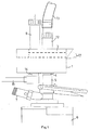
- the device according to the invention consists of a valve housing 1 designed as a block, in which there is a T-shaped groove 2 for receiving a correspondingly designed, T-shaped valve slide 3.
- connection 4 is provided for the beverage supply, which is directly on an extension 5 of a beverage container 6, for example a beer keg, is placed.
- a connection 7 is provided for the CO2, which is supplied by a CO2 bottle, not shown.
- a cylindrical magazine 9 is arranged above a bore 8 in the spool 3, in which there are elastic, spherical cleaning bodies 10, for example small balls or sponges.
- a connecting piece 12 is arranged over a further bore 11 in the valve slide 3, which is connected to a flexible beverage line 13, which leads to the bar.
- a threaded connection 14 for the supply line 15 for the cleaning water is also provided in addition to the connection 4 for the beverage supply.
- the threaded connection 14 for the supply of cleaning water and the connection 4 for the supply of drinks in the lower part of the valve housing 1 have the same distance from one another as the two through holes 8 and 11 in the valve slide.
- a pressure piston arrangement 16 is also arranged in the valve housing 1, the connection 17 of which is connected to the CO2 bottle, not shown.
- the pressure piston can be triggered by a remote control device (not shown), so that the device can be operated from any location within a certain radius.
- Fig. 2 is in the upper part of the connecting piece 14 for the cleaning water supply Room 18 for receiving a spherical, elastic cleaning body 10 is provided, which falls from the tubular magazine 9 in the position of the operating state described below in this room.
- the connecting pieces 4 and 14 also have cylindrical inserts 21, 22 loaded by coil springs 19, 20, which press against the lower surface of the slide 3 for sealing.
- the magazine 9 is in correspondence with the water connection 14, so that a cleaning body 10 falls into the upper space 18 by gravity.
- the bore 11 is in line with the connection 4, so that, starting from the beverage container 6, the beverage is guided in the direction of arrow 24 through the flexible line 13 to the dispenser.
- FIGS. 4 and 5 The cleaning or emptying state is shown in FIGS. 4 and 5.
- the slide 3 is moved in the direction of the double arrow 25 to the left, so that the outlet of the magazine 9 is closed by the base of the valve housing 1. Furthermore, the connection 4 for the beverage supply is closed by the base 23 of the slide 3.
- connection piece 12 with the through hole 11 is in this position above the connection 14 for the water supply.
- the pressure of the water column pushes the cleaning body 10 upwards into the flexible line 13 and from there to the dispenser.
- the boundary between the rising column of water and the beverage column located in the line 13 forms the spherical, elastic cleaning body 10.
- the person operating the tap can therefore still use the beverage standing in the beverage line 13 until the cleaning body 10 emerges from the tap at the dispenser. If the remaining amount of beverage is predetermined, the person serving the drink knows exactly how much beverage can still be administered. As a result, the device according to the invention works without loss of drinks.
- FIG. 6 shows a section through another embodiment of the invention corresponding to FIG. 5.
- the slide 3 ' is dovetail-shaped and runs in a corresponding dovetail-shaped recess 2'.
- other forms of training of the slide are also possible. It is only essential that it is clearly guided in the valve housing 1.
- the slide is also possible to design the slide as a rotary slide valve, in which case the valve housing has a circular shape in which the corresponding connecting pieces are located.
- the device according to the invention is not only intended for a beverage dispensing system, for example a beer dispensing system, but rather can also be used in systems for other liquids and liquid foods, such as milk, milk products or the like.
- This application is intended in particular for the industrial production and processing of liquids and food, such as in milk centers, at beverage manufacturers, etc.
- FIGS. 7 to 9 show a modified embodiment the device according to the invention shown using a rotary slide valve.
- the rotary slide valve 26 is located there within a valve housing 28 which has a semicircular region 27.
- the bent connection piece 29 leads to the flexible beverage line for serving.
- the beverage inlet connector 4 and the connector 14 for the cleaning water supply are arranged in the lower part of the valve housing 28, with instead of the longitudinal movement of the slide 26 executing a rotary movement either to connect the connector 4 to the curved connector 29 or after a rotary movement, the connection for the To connect cleaning water supply together with the cleaning body 10 located therein to the connecting piece 29.
- two pressure connections 30, 31 are provided, behind which pressure pistons 32, 33 are arranged in suitable guides.
- the pressure pistons are connected to metal balls 34, which bear against a part 35 of the rotary valve 26. Depending on which pressure piston 32, 33 is pressurized, the part 35 is brought into the corresponding end position by the balls 34. This also triggers the previously described rotary movement of the connecting pieces 4, 14.
- a further change to the device according to the invention can consist in providing a switching valve in the water supply line to the water connection 14, which valve is blocked when the magazine 9 is located above the water connection 14. In this way, the magazine space can be kept free of pressurized water during the fall of the cleaning body 10 into the space 18.
Landscapes
- Engineering & Computer Science (AREA)
- Mechanical Engineering (AREA)
- General Engineering & Computer Science (AREA)
- Physics & Mathematics (AREA)
- Fluid Mechanics (AREA)
- Devices For Dispensing Beverages (AREA)
- Cleaning In General (AREA)
- Medicines That Contain Protein Lipid Enzymes And Other Medicines (AREA)
- Non-Alcoholic Beverages (AREA)
- Apparatus For Making Beverages (AREA)
Abstract
Description
Die Erfindung betrifft eine Vorrichtung zum Reinigen und Entleeren von Flüssigkeitsleitungen, insbesondere Getränkeleitungen in Zapfanlagen, mit einem Schieber- oder Drehschieberventil, bei dem der Ventilschieber in einer Aussparung eines Ventilgehäuses derart beweglich ist, daß mindestens eine Querbohrung im Ventilschieber in Verbindung mit einem Anschlußstutzen für den Einlauf des Getränkes gebracht werden kann, und mit einem zylinderförmigen Magazin für elastische, kugelförmige Reinigungskörper sowie einem Anschlußstutzen für die Wasserzufuhr.The invention relates to a device for cleaning and emptying liquid lines, in particular beverage lines in dispensing systems, with a slide or rotary slide valve, in which the valve slide is movable in a recess in a valve housing in such a way that at least one transverse bore in the valve slide in connection with a connecting piece for the Inlet of the beverage can be brought, and with a cylindrical magazine for elastic, spherical cleaning bodies and a connecting piece for the water supply.
Die Erfindung geht aus von einer Reinigungsvorrichtung, wie sie in der DE-OS 35 04 636 beschrieben ist. Bei dieser ser Reinigungsvorrichtung sind in der Oberwand und in der Unterwand des Ventilgehäuses ein Anschlußstutzen für die zum Zapfhahn führende Getränkeleitung und ein Anschlußstutzen für die zum Faß führende Getränkeleitung vorgesehen. Ferner ist je ein Gewindeanschluß für die Zu- und Abfuhr des Wassers vorgesehen. Ein Magazin für kugelförmige, elastische Reinigungskörper ist an der Oberwand des Ventilgehäuses befestigt. Der Ventilschieber ist zweiteilig aufgebaut und weist einen um seine Längsachse drehbaren Schaltkörper auf, der mit einer zentralen, bis in eine Endkugel reichende Zentralbohrung versehen ist.The invention is based on a cleaning device as described in DE-OS 35 04 636. At this Water cleaning device are provided in the upper wall and in the lower wall of the valve housing a connection piece for the beverage line leading to the tap and a connection piece for the beverage line leading to the barrel. Furthermore, a threaded connection is provided for the supply and discharge of the water. A magazine for spherical, elastic cleaning bodies is attached to the upper wall of the valve housing. The valve slide is constructed in two parts and has a switch body which can be rotated about its longitudinal axis and which is provided with a central central bore extending into an end ball.
Mit der vorbekannten Vorrichtung soll abwechselnd die zum Faß und die zum Zapfhahn führende Getränkeleitung gereinigt werden, wobei bei Betriebs- oder Zapfstellung keine Beunruhigung des Getränkes verursacht wird.With the known device, the beverage line leading to the barrel and the tap leading to the tap are to be cleaned alternately, with no disturbance of the beverage being caused in the operating or dispensing position.
Die vorbekannte Vorrichtung ist verhältnismäßig kompliziert aufgebaut und kann nur an Ort und Stelle mittels eines Schieb- und Drehschalthebels betätigt werden. Außerdem kann die Reinigung der zum Faß und der zum Zapfhahn führenden Getränkeleitung nur abwechselnd erfolgen.The known device is relatively complicated and can only be actuated on the spot by means of a slide and rotary switch lever. In addition, the cleaning of the beverage line leading to the barrel and the tap leading to the tap can only be carried out alternately.
Der vorliegenden Erfindung liegt die Aufgabe zugrunde, die vorbekannte Reinigungsvorrichtung im Hinblick auf den Aufbau und den Betriebsablauf zwischen Zapfbetrieb und Reinigungsbetrieb wesentlich zu vereinfachen.The present invention has for its object to simplify the previously known cleaning device with regard to the structure and the operational sequence between tap operation and cleaning operation.
Diese Aufgabe wird gemäß der Erfindung dadurch gelöst, daß das zylinderförmige Magazin für die elastischen, kugelförmigen Reinigungskörper und der zu einer flexiblen Getränkeleitung zum Ausschank führende Anschlußstutzen unmittelbar an der Oberseite des durch eine geeignete Antriebseinrichtung betätigbaren Ventilschiebers über je einer entsprechenden Durchbohrung derselben angeordnet und mit diesem verschiebbar sind, wobei der Gewindeanschluß für die Reinigungswasserzufuhr und der Anschluß für die Getränkezufuhr im unteren Teil des Ventilgehäuses im Abstand voneinander angeordnet sind, derart, daß in der einen Endstellung des Schiebers im Betriebszustand die beiden Durchbohrungen zur Deckung mit den beiden Anschlußstutzen im unteren Teil des Ventilgehäuses gebracht werden und im Reinigungs- bzw. Entleerungszustand der Anschluß für die Getränkezufuhr geschlossen und die zum Ausschank führende Getränkeleitung mit dem Gewindeanschluß für die Reinigungswasserzufuhr verbunden ist.This object is achieved according to the invention in that the cylindrical magazine for the elastic, spherical cleaning body and the connecting piece leading to a flexible beverage line for serving are arranged directly on the upper side of the valve slide which can be actuated by a suitable drive device and each with a corresponding bore are displaceable, the threaded connection for the cleaning water supply and the connection for the beverage supply in the lower part of the valve housing being arranged at a distance from one another, such that in the one end position of the slide in the operating state the two through-holes cover the two connecting pieces in the lower part of the valve body Be brought valve housing and in the cleaning or emptying state, the connection for the beverage supply closed and the beverage line leading to the bar with the threaded connection for the cleaning water drove is connected.
Gemäß dem Merkmal des Patentanspruches 2 weisen der Gewindeanschluß und der Anschluß für die Getränkezufuhr im unteren Teil des Ventilgehäuses den gleichen Abstand voneinander wie die beiden Durchgangsbohrungen im Ventilschieber auf.According to the feature of
Gemäß dem Merkmal des Anspruches 3 weisen der Gewindeanschluß und der Anschluß für die Getränkezufuhr im unteren Teil des Ventilgehäuses einen größeren Abstand voneinander wie die beiden Durchgangsbohrungen im Ventilschieber auf.According to the feature of
Gemäß dem Merkmal des Patentanspruches 4 ist im oberen Teil des Gewindeanschlusses für die Reinigungswasserzufuhr ein Raum zur Aufnahme eines kugelförmigen, elastischen Reinigungskörpers vorgesehen, der vom rohrförmigen Magazin bei der Stellung des Betriebszustandes in diesen Raum fällt und in der Stellung des Reinigungszustandes von der Wassersäule durch die zum Ausschank führende Getränkeleitung gedrückt wird.According to the feature of
Mit der Reinigungsvorrichtung gemäß der Erfindung wird der wesentliche Vorteil erreicht, daß mit einem gegenüber der durch die DE-OS 35 04 636 vorbekannten Vorrichtung wesentlich einfacheren Schieber- oder Drehschieberventil der Reinigungs- und Entleerungsvorgang in der zum Ausschank führenden Getränkeleitung durchgeführt werden kann. Durch den besonders einfachen Aufbau ist es auch möglich, die Vorrichtung gemäß der Erfindung unmittelbar auf den Getränkebehälter, beispielsweise ein Bierfaß, aufzusetzen, so daß zwischen dem Bierfaß und der Vorrichtung gemäß der Erfindung eine besondere Zuleitung wegfallen kann.With the cleaning device according to the invention the main advantage is achieved that with a compared to the device known from DE-OS 35 04 636 much simpler slide or rotary slide valve, the cleaning and emptying process can be carried out in the beverage line leading to the bar. Due to the particularly simple construction, it is also possible to place the device according to the invention directly on the beverage container, for example a beer keg, so that a special feed line can be omitted between the beer keg and the device according to the invention.
Ein weiterer Vorteil der erfindungsgemäßen Vorrichtung besteht darin, daß die Reinigung der zum Ausschank führenden Getränkeleitung ohne Getränkeverlust durchgeführt werden kann, da das in der Leitung stehende Getränk bei Einleitung des Reinigungsvorganges bis zum Erscheinen des Reinigungskörpers noch voll verwendbar ist.Another advantage of the device according to the invention is that the cleaning leading to the bar Beverage line can be carried out without loss of beverage, since the beverage in the line is still fully usable when the cleaning process is initiated until the cleaning body appears.
Durch die besondere Anordnung des Magazins für die Reinigungskörper unmittelbar auf dem Schieber des Schieber- oder Drehschieberventils wird das Problem der Dichtung von beweglichen Teilen nur zwischen den Anschlüssen im unteren Teil des Ventilgehäuses und dem Schieber auftreten. Diese Lösung ist deshalb besonders vorteilhaft, weil mit dem Schieber oder Drehschieber unmittelbar eine flexible Getränkeleitung, die zum Ausschank führt, verbunden wird. Selbstverständlich kann diese flexible Leitung auch nur aus einem Teil einer Gesamtleitung bestehen, wobei die Flexibilität dieser Leitung nur in bezug auf den Schieberweg des Schieberventils berücksichtigt werden muß.Due to the special arrangement of the magazine for the cleaning body directly on the slide of the slide or rotary slide valve, the problem of sealing moving parts will only occur between the connections in the lower part of the valve housing and the slide. This solution is particularly advantageous because a flexible beverage line leading to the bar is connected directly to the slide or rotary slide valve. Of course, this flexible line can also consist of only part of an overall line, the flexibility of this line only having to be taken into account with regard to the slide travel of the slide valve.
Gemäß Anspruch 5 besteht die Antriebseinrichtung zur Betätigung des Ventilschiebers aus einem gegebenenfalls fernsteuerbaren Druckkolben, der von einer CO₂-Druckflasche, die beispielsweise beim Zapfen von Bier benötigt wird, beaufschlagt wird.According to
Gemäß Anspruch 6 kann der Schieber zur Längsbewegung im Ventilgehäuse ein Querschnittsprofil, beispielsweise ein Schwalbenschwanzprofil, aufweisen, um eine Führung in einer entsprechenden Nut innerhalb des Ventilgehäuses zu gewährleisten.According to
Die Anschlußstutzen im unteren Teil des Ventilgehäuses können mit federbelasteten, zylindrischen Einsätzen zur Abdichtung gegen die untere Fläche des Schiebers versehen werden.The connecting pieces in the lower part of the valve housing can be provided with spring-loaded, cylindrical inserts for sealing against the lower surface of the slide.
Schließlich kann die gesamte Vorrichtung gemäß der Erfindung gemäß Anspruch 8 mit einem Anschlußstutzen für die Getränkezufuhr versehen werden, der ein Ansatzstück zum direkten Aufsetzen auf ein Getränkefaß aufweist.Finally, the entire device according to the invention according to claim 8 can be provided with a connecting piece for the beverage supply, which has an attachment for direct placement on a beverage keg.
Anhand der Zeichnungen soll am Beispiel bevorzugter Ausführungsformen die Vorrichtung gemäß der Erfindung näher erläutert werden.Using the drawings, the device according to the invention will be explained in more detail using the example of preferred embodiments.
In den Zeichnungen zeigt
- Fig. 1
- eine prizipielle Seitenansicht einer Vorrichtung gemäß der Erfindung.
- Die
Figuren 2 und 3 - zeigen je einen Längs- und einen Querschnitt der Vorrichtung gemäß Fig. 1 im Betriebszustand, d. h. in der Schankstellung.
- Die
Figuren 4 und 5 - zeigen entsprechende Schnitte wie die
Figuren 2 und 3 im Entleerungs- und Reinigungszustand. - Fig. 6
- zeigt einen Querschnitt durch eine Vorrichtung gemäß der Erfindung mit schwalbenschwanzförmigem Ventilschieber.
- Die
Figuren 7 bis 9 - zeigen eine abgewandelte Ausführungsform der Vorrichtung gemäß der Erfindung.
- Fig. 1
- a basic side view of a device according to the invention.
- Figures 2 and 3
- each show a longitudinal and a cross section of the device according to FIG. 1 in the operating state, ie in the dispensing position.
- Figures 4 and 5
- show corresponding sections as Figures 2 and 3 in the emptying and cleaning state.
- Fig. 6
- shows a cross section through a device according to the invention with dovetail valve spool.
- Figures 7 to 9
- show a modified embodiment of the device according to the invention.
Wie sich aus den Figuren der Zeichnung ergibt, besteht die Vorrichtung gemäß der Erfindung aus einem als Block ausgebildeten Ventilgehäuse 1, in dem sich eine T-förmige Nut 2 zur Aufnahme eines entsprechend ausgebildeten, T-förmigen Ventilschiebers 3 befindet.As can be seen from the figures of the drawing, the device according to the invention consists of a
In der Unterseite des Ventilgehäuses 1 ist ein Anschluß 4 für die Getränkezufuhr vorgesehen, der unmittelbar auf ein Ansatzstück 5 eines Getränkebehälters 6, beispielsweise eines Bierfasses, aufgesetzt ist. Unterhalb des Anschlußstückes 5 ist ein Anschluß 7 für das CO₂ vorgesehen, das von einer nicht dargestellten CO₂-Flasche geliefert wird.In the bottom of the
Unmittelbar an der Oberseite des Ventilschiebers 3 ist über einer Durchbohrung 8 im Schieber 3 ein zylinderförmiges Magazin 9 angeordnet, in dem sich elastische, kugelförmige Reinigungskörper 10, beispielsweise kleine Bällchen oder Schwämmchen, befinden. Im Abstand davon ist über einer weiteren Bohrung 11 im Ventilschieber 3 ein Anschlußstutzen 12 angeordnet, der mit einer flexiblen Getränkeleitung 13 verbunden ist, die zum Ausschank führt.Immediately on the top of the
Im unteren Teil des Ventilgehäuses 1 ist ferner neben dem Anschluß 4 für die Getränkezufuhr ein Gewindeanschluß 14 für die Zuleitung 15 für das Reinigungswasser vorgesehen.In the lower part of the
Um die Funktion der Vorrichtung gemäß der Erfindung zu gewährleisten, weisen der Gewindeanschluß 14 für die Reinigungswasserzufuhr und der Anschluß 4 für die Getränkezufuhr im unteren Teil des Ventilgehäuses 1 den gleichen Abstand wie die beiden Durchbohrungen 8 bzw. 11 im Ventilschieber voneinander auf.In order to ensure the function of the device according to the invention, the threaded
Zur Betätigung des Ventilschiebers ist ferner eine Druckkolbenanordnung 16 im Ventilgehäuse 1 angeordnet, deren Anschluß 17 mit der nicht dargestellten CO₂-Flasche in Verbindung steht. Die Auslösung des Druckkolbens kann durch eine nicht dargestellte Fernsteuereinrichtung erfolgen, so daß die Vorrichtung innerhalb eines gewissen Radius von beliebiger Stelle aus bedient werden kann.To actuate the valve slide, a
Wie sich insbesondere aus Fig. 2 ergibt, ist im oberen Teil des Anschlußstutzens 14 für die Reinigungswasserzufuhr ein Raum 18 zur Aufnahme eines kugelförmigen, elastischen Reinigungskörpers 10 vorgesehen, der vom rohrförmigen Magazin 9 in der nachfolgend noch beschriebenen Stellung des Betriebszustandes in diesen Raum fällt.As can be seen in particular from Fig. 2, is in the upper part of the connecting
Die Anschlußstutzen 4 und 14 weisen ferner durch Schraubenfedern 19, 20 belastete, zylindrische Einsätze 21, 22 auf, die zur Abdichtung gegen die untere Fläche des Schiebers 3 drücken.The connecting
Die Funktion der Vorrichtung gemäß der Erfindung soll nun anhand der Figuren 2 bis 5 näher erläutert werden.The function of the device according to the invention will now be explained in more detail with reference to FIGS. 2 to 5.
In den Figuren 2 und 3, welche die Betriebsstellung darstellen, befindet sich das Magazin 9 in Übereinstimmung mit dem Wasseranschluß 14, so daß durch Schwerkraft in den oberen Raum 18 ein Reinigungskörper 10 fällt. Die Bohrung 11 befindet sich in Übereinstimmung mit dem Anschluß 4, so daß, ausgehend vom Getränkebehälter 6, das Getränk in Richtung des Pfeiles 24 durch die flexible Leitung 13 zum Ausschank geführt wird.In Figures 2 and 3, which represent the operating position, the
In den Figuren 4 und 5 ist der Reinigungs- bzw. Entleerungszustand dargestellt. Der Schieber 3 ist in Richtung des Doppelpfeils 25 nach links bewegt, so daß der Austritt des Magazins 9 durch die Grundfläche des Ventilgehäuses 1 geschlossen wird. Ferner wird der Anschluß 4 für die Getränkezufuhr durch die Grundfläche 23 des Schiebers 3 geschlossen.The cleaning or emptying state is shown in FIGS. 4 and 5. The
Der Anschlußstutzen 12 mit der Durchbohrung 11 befindet sich in dieser Stellung über dem Anschluß 14 für die Wasserzufuhr. Durch den Druck der Wassersäule wird der Reinigungskörper 10 nach oben in die flexible Leitung 13 und von da bis zum Ausschank gedrückt. Die Grenze zwischen der aufsteigenden Wassersäule und der sich in der Leitung 13 befindlichen Getränkesäule bildet der kugelförmige, elastische Reinigungskörper 10.The
Die den Schankhahn bedienende Person kann also das in der Getränkeleitung 13 stehende Getränk noch verwenden, und zwar so lange, bis der Reinigungskörper 10 aus dem Getränkehahn am Ausschank austritt. Wenn die noch vorhandene Getränkemenge vorbestimmt ist, weiß die ausschenkende Person genau, wieviel Getränk noch verabreicht werden kann. Dadurch arbeitet die Vorrichtung gemäß der Erfindung ohne Getränkeverlust.The person operating the tap can therefore still use the beverage standing in the
In Fig. 6 ist ein Schnitt durch eine andere Ausführungsform der Erfindung entsprechend Fig. 5 dargestellt. Der Schieber 3' ist dabei schwalbenschwanzförmig ausgebildet und läuft in einer entsprechenden, schwalbenschwanzförmig ausgebildeten Aussparung 2'. Selbstverständlich sind auch andere Ausbildungsformen des Schiebers möglich. Wesentlich ist dabei nur, daß er im Ventilgehäuse 1 eindeutig geführt wird.FIG. 6 shows a section through another embodiment of the invention corresponding to FIG. 5. The slide 3 'is dovetail-shaped and runs in a corresponding dovetail-shaped recess 2'. Of course, other forms of training of the slide are also possible. It is only essential that it is clearly guided in the
Es ist auch möglich, den Schieber als Drehschieber auszubilden, wobei dann das Ventilgehäuse eine kreisrunde Form aufweist, in der sich die entsprechenden Anschlußstutzen befinden.It is also possible to design the slide as a rotary slide valve, in which case the valve housing has a circular shape in which the corresponding connecting pieces are located.
Die Vorrichtung gemäß der Erfindung ist nicht nur für eine Getränkeschankanlage, beispielsweise eine Bierschankanlage, vorgesehen, sondern sie kann vielmehr auch bei Anlagen für andere Flüssigkeiten und flüssige Lebensmittel, wie Milch, Milcherzeugnisse od. dgl., eingesetzt werden. Dieser Einsatz ist insbesondere bei der industriellen Herstellung und Aufbereitung der Flüssigkeiten und Lebensmittel, wie in Milchzentralen, bei Getränkeherstellern usw., gedacht.The device according to the invention is not only intended for a beverage dispensing system, for example a beer dispensing system, but rather can also be used in systems for other liquids and liquid foods, such as milk, milk products or the like. This application is intended in particular for the industrial production and processing of liquids and food, such as in milk centers, at beverage manufacturers, etc.
In den Figuren 7 bis 9 ist eine abgewandelte Ausführungsform der Vorrichtung gemäß der Erfindung unter Anwendung eines Drehschieberventils dargestellt.FIGS. 7 to 9 show a modified embodiment the device according to the invention shown using a rotary slide valve.
Der Drehschieber 26 befindet sich dort innerhalb eines einen halbkreisförmigen Bereich 27 aufweisenden Ventilgehäuses 28. Der gebogene Anschlußstutzen 29 führt zur flexiblen Getränkeleitung zum Ausschank. Der Getränkeeinlaufstutzen 4 und der Stutzen 14 für die Reinigungswasserzufuhr sind im unteren Teil des Ventilgehäuses 28 angeordnet, wobei anstelle der Längsbewegung der Schieber 26 eine Drehbewegung ausführt, um entweder den Anschlußstutzen 4 mit dem gebogenen Anschlußstutzen 29 zu verbinden oder nach einer Drehbewegung den Anschluß für die Reinigungswasserzufuhr zusammen mit dem darin befindlichen Reinigungskörper 10 mit dem Anschlußstutzen 29 zu verbinden. Hierzu sind zwei Druckanschlüsse 30, 31 vorgesehen, hinter denen in geeigneten Führungen Druckkolben 32, 33 angeordnet sind. Die Druckkolben stehen mit Metallkugeln 34 in Verbindung, die gegen ein Teil 35 des Drehschiebers 26 anliegen. Je nachdem, welcher Druckkolben 32, 33 mit Druck beaufschlagt wird, wird das Teil 35 durch die Kugeln 34 in die entsprechende Endstellung gebracht. Damit wird auch die zuvor beschriebene Drehbewegung der Anschlußstutzen 4, 14 ausgelöst.The
Es ist selbstverständlich auch möglich, in Abwandlung der in den Figuren 2 und 4 dargestellten Ausführungsform den Abstand des Gewindeanschlusses 14 für die Reinigungswasserzufuhr und des Anschlusses 4 für die Getränkezufuhr im unteren Teil des Ventilgehäuses größer zu machen als der Abstand der beiden Durchgangsbohrungen 8, 11 im Ventilschieber 3. Hierbei kommt es im wesentlichen darauf an, daß nur zum Einführen des Reinigungskörpers 10 in den Raum 18 das Magazin 9 und der Wasseranschluß 14 übereinander stehen, wobei dann der Verschiebeweg etwas größer wird.It is of course also possible, in a modification of the embodiment shown in FIGS. 2 and 4, to make the distance between the threaded
Eine weitere Änderung der erfindungsgemäßen Vorrichtung kann darin bestehen, in der Wasserzuführungsleitung zum Wasseranschluß 14 ein Schaltventil vorzusehen, das dann gesperrt wird, wenn sich das Magazin 9 über dem Wasseranschluß 14 befindet. Auf diese Weise kann der Magazinraum während des Herunterfallens des Reinigungskörpers 10 in den Raum 18 druckwasserfrei gehalten werden.A further change to the device according to the invention can consist in providing a switching valve in the water supply line to the
Claims (11)
- Device for cleaning and draining conduits containing liquids, in particular beverage conduits in tapping installations, with a sliding or sliding and rotating valve, in which the valve slider is so movable in a recess in the valve housing that at least one transverse bore in the slider can be brought into communication with a connection for the entry of the beverage, and with a cylindrical magazine for elastic, ball-shaped cleaning bodies and a connection for the water supply, characterised in that the cylindrical magazine (9) for the elastic ball-shaped cleaning bodies (10) and the connection leading to a flexible beverage conduit (13) at the dispensing point is arranged directly on the upper side of the valve slider (3, 3'), activated by a suitable drive mechanism, each via a corresponding bore, and is movable with this, wherein the threaded connection (14) for the cleaning water supply and the connection (4) for the beverage supply housing (1) are arranged at a distance from one another in the lower part of the valve housing (1) such that both holes (8, 11) are brought to a position covering both connections (4, 14) in the lower part of the valve housing in one of the final positions of the slide valve, and during the cleaning or draining operation the connection (4) for the drink supply is closed and the beverage conduit (13) leading to the dispensing unit is joined to the threaded connection (14) for the cleaning water supply.
- Device according to Claim 1, characterised in that the threaded connection (14) and the connection (4) are located at the same distance from one another as both holes (8, 11) in the valve slider (3).
- Device according to Claim 3, characterised in that the threaded connection (14) and the connection (4) are located at a greater distance from one another than both holes (8, 11) in the valve slider (3).
- Device according to Claim 1, 2 or 3, characterised in that in the upper part of the threaded connector for the cleaning water supply, a space (18) is provided for a ball-shaped, elastic cleaning body (10), which drops from the tubular magazine (9) into this space in the operating condition and in the cleaning condition is pressed by the water column towards the dispensing unit through the beverage conduit (13) leading to the dispensing unit.
- Device according to Claim 1, 2 or 3 and 4, characterised in that the drive device for activating the valve slider (3, 3') consists of an optionally remotely-controlled pressure piston (16) which is operated by a flask of compressed CO₂.
- Device according to Claim 1, 2 or 3, 4 or 5, characterised in that the valve slider (3, 3') for longitudinal movement in the valve housing (1) has a corresponding cross-sectional profile, example a dovetail profile or a T-profile, and slides in a correspondingly shaped groove (2, 2') in the valve housing (1).
- Device according to one or several of the above claims, characterised in that the connectors (4, 14) on the lower side of the valve housing (1) press for sealing against the lower surface (23) of the sliding unit (3) with cylindrical tops (21, 22) pressed by coil springs (19, 20).
- Device according to one or several of the above claims, characterised in that the connection (4) for the drink supply is provided with an extension piece (5) for placing directly on the drinks barrel (6).
- Device according to Claim 1, 2 or 3 and 4, characterised in that in a semi-circular valve housing (27, 28) a rotary slider (26) is arranged which can be moved to two final positions by means of pistons (32, 33) in conjunction with balls (24) guided through channels, and that these two positions correspond to the operating condition or the draining condition of the individual connections.
- Device according to Claim 1, 2, or 3 up to Claim 7, characterised in that an on-off valve is arranged in the conduit leading to the connection (14) for water supply.
- Device according to one of claims 1, 3 or 6, characterised in that in the valve housing (1) in the region of the connections (12) fitted to the valve slider (3) and of the magazine (9), an opening is provided going from the recess (2) guiding the valve slider (3), in which opening the connection (12) and the magazine (9) project from the valve housing (1) and both parts (9, 12) are adjustable when the valve slider (3) is moved.
Priority Applications (1)
| Application Number | Priority Date | Filing Date | Title |
|---|---|---|---|
| AT90123908T ATE92793T1 (en) | 1989-12-23 | 1990-12-12 | DEVICE FOR CLEANING AND EMPTYING LIQUID LINES, PARTICULARLY BEVERAGE LINES IN DRAFT SYSTEMS. |
Applications Claiming Priority (2)
| Application Number | Priority Date | Filing Date | Title |
|---|---|---|---|
| DE3942788 | 1989-12-23 | ||
| DE3942788A DE3942788A1 (en) | 1989-12-23 | 1989-12-23 | DEVICE FOR CLEANING AND EMPTYING LIQUID LINES, IN PARTICULAR DRINKING LINES IN TAPPING PLANTS |
Publications (2)
| Publication Number | Publication Date |
|---|---|
| EP0437733A1 EP0437733A1 (en) | 1991-07-24 |
| EP0437733B1 true EP0437733B1 (en) | 1993-08-11 |
Family
ID=6396315
Family Applications (1)
| Application Number | Title | Priority Date | Filing Date |
|---|---|---|---|
| EP90123908A Expired - Lifetime EP0437733B1 (en) | 1989-12-23 | 1990-12-12 | Cleaning and emptying system for fluid conduits, especially for beverage conduits in tapping installations |
Country Status (10)
| Country | Link |
|---|---|
| EP (1) | EP0437733B1 (en) |
| JP (1) | JP2571990B2 (en) |
| AT (1) | ATE92793T1 (en) |
| AU (1) | AU6917691A (en) |
| CA (1) | CA2071991A1 (en) |
| CS (1) | CS656890A3 (en) |
| DE (2) | DE3942788A1 (en) |
| ES (1) | ES2045735T3 (en) |
| PL (1) | PL288417A1 (en) |
| WO (1) | WO1991009692A1 (en) |
Families Citing this family (7)
| Publication number | Priority date | Publication date | Assignee | Title |
|---|---|---|---|---|
| DE9110219U1 (en) * | 1991-08-19 | 1991-10-24 | Till, Sascha, 7573 Sinzheim, De | |
| DE9113488U1 (en) * | 1991-10-30 | 1992-02-06 | Till, Rudolf, 7573 Sinzheim, De | |
| DE4221577C2 (en) * | 1992-07-01 | 1995-04-13 | Bersch Friedrich | Device for cleaning pipelines |
| AU4038493A (en) * | 1992-11-04 | 1994-05-24 | Kundo Systemtechnik Gmbh | Drink-retailing apparatus |
| DK0641736T3 (en) * | 1993-01-25 | 2000-07-03 | Kirin Brewery | Beverage drain system cleaning device |
| DE19542840A1 (en) * | 1995-11-17 | 1997-05-22 | Kundo Systemtechnik Gmbh | Cleaning system for drink dispensing tap |
| NL1032098C2 (en) | 2006-06-30 | 2008-01-02 | Heineken Supply Chain Bv | Tapping device, beverage container, coupling device and method with cleaning element. |
Family Cites Families (7)
| Publication number | Priority date | Publication date | Assignee | Title |
|---|---|---|---|---|
| DE318557C (en) * | ||||
| FR2030196A1 (en) * | 1969-01-27 | 1970-10-30 | Ite Imperial Corp | |
| DE2943967A1 (en) * | 1979-10-31 | 1981-05-14 | Friedrich Wilh. Schwing Gmbh, 4690 Herne | Cleaning device for concrete pump - has chamber containing cleaning ball, moved from external disengaged position into injection position |
| DE2927324C3 (en) * | 1979-07-06 | 1994-09-15 | Schwing Gmbh F | Pipe fitting with a housing that can be installed in lines that convey pressurized thick materials, preferably concrete, for changing a wiper |
| DE3322908A1 (en) * | 1983-06-25 | 1985-01-10 | Ewald 5403 Mülheim-Kärlich Wagner | Cleaning device for tapping apparatuses |
| DE3504636A1 (en) * | 1985-02-11 | 1986-08-14 | Ewald 5403 Mülheim-Kärlich Wagner | Cleaning apparatus for drink tapping systems |
| DE8708749U1 (en) * | 1987-06-24 | 1987-08-20 | Bergwerksverband Gmbh, 4300 Essen, De |
-
1989
- 1989-12-23 DE DE3942788A patent/DE3942788A1/en not_active Withdrawn
-
1990
- 1990-12-12 ES ES90123908T patent/ES2045735T3/en not_active Expired - Lifetime
- 1990-12-12 DE DE9090123908T patent/DE59002315D1/en not_active Expired - Fee Related
- 1990-12-12 EP EP90123908A patent/EP0437733B1/en not_active Expired - Lifetime
- 1990-12-12 AT AT90123908T patent/ATE92793T1/en not_active IP Right Cessation
- 1990-12-21 WO PCT/DE1990/000993 patent/WO1991009692A1/en active Application Filing
- 1990-12-21 CA CA002071991A patent/CA2071991A1/en not_active Abandoned
- 1990-12-21 JP JP3501189A patent/JP2571990B2/en not_active Expired - Lifetime
- 1990-12-21 AU AU69176/91A patent/AU6917691A/en not_active Abandoned
- 1990-12-21 CS CS906568A patent/CS656890A3/en unknown
- 1990-12-21 PL PL28841790A patent/PL288417A1/en unknown
Also Published As
| Publication number | Publication date |
|---|---|
| ATE92793T1 (en) | 1993-08-15 |
| DE59002315D1 (en) | 1993-09-16 |
| DE3942788A1 (en) | 1991-07-04 |
| JP2571990B2 (en) | 1997-01-16 |
| EP0437733A1 (en) | 1991-07-24 |
| CS656890A3 (en) | 1992-05-13 |
| PL288417A1 (en) | 1991-09-09 |
| WO1991009692A1 (en) | 1991-07-11 |
| ES2045735T3 (en) | 1994-01-16 |
| AU6917691A (en) | 1991-07-24 |
| CA2071991A1 (en) | 1991-06-24 |
| JPH05504531A (en) | 1993-07-15 |
Similar Documents
| Publication | Publication Date | Title |
|---|---|---|
| EP0132457B1 (en) | Assembly for dispensing multicomponent products | |
| DE3916952C1 (en) | ||
| EP0455650B1 (en) | Tap head for keg fittings | |
| EP0437733B1 (en) | Cleaning and emptying system for fluid conduits, especially for beverage conduits in tapping installations | |
| DE20004615U1 (en) | Flow control device for a gun nozzle | |
| DE1532664A1 (en) | Device for mixing and dispensing several liquids | |
| DE3244019C2 (en) | Industrial robots | |
| EP0421194A2 (en) | Spraygun for a high pressure cleaning device | |
| EP0987214B1 (en) | Tapping head with only one connector for rinsing fluid, beverage and gas | |
| DE3221589C2 (en) | Device for the automatic production of cleaning water | |
| EP0564626B1 (en) | Device for cleaning and emptying liquid beverage ducts in taps | |
| DE3114307A1 (en) | Cleaning device for the mixing chamber of a concrete mixer | |
| DE3124125A1 (en) | High pressure spray gun | |
| DE2920858A1 (en) | ELECTRIC LUBRICATION DEVICE | |
| EP3762154B1 (en) | Multiway flood valve for technical liquids with linear flood flow control | |
| DE2609791A1 (en) | Pipe coupling for food industry - has separate channels to control flow of cleaning liquid from pressure operated valve | |
| DE3339591A1 (en) | Actuating device for servo cylinders for assisting the shifting process in a gearbox | |
| DE3134820C2 (en) | Electromotive actuator drive for valves or the like. | |
| EP0424571A1 (en) | Device for micro-spraying liquids | |
| WO2000076671A1 (en) | Switching nozzle for a high-pressure cleaning device | |
| EP0572836B1 (en) | Self-closing valve | |
| DE3102787A1 (en) | GEARBOX MECHANISM FOR A SNAPSHIFT SWITCH FOR SWITCHING A MEDIUM PRESSURIZED IN A CYLINDER PISTON SYSTEM, ESPECIALLY FOR A PRESSURE TRANSLATOR | |
| DE4320379A1 (en) | Device for the removal of cleaning bodies at compensation stopcocks of dispensing systems | |
| DE1559114C (en) | Pool cleaner | |
| DE3529817A1 (en) | Container with a closable outlet aperture |
Legal Events
| Date | Code | Title | Description |
|---|---|---|---|
| PUAI | Public reference made under article 153(3) epc to a published international application that has entered the european phase |
Free format text: ORIGINAL CODE: 0009012 |
|
| AK | Designated contracting states |
Kind code of ref document: A1 Designated state(s): AT BE CH DE DK ES FR GB GR IT LI LU NL SE |
|
| 17P | Request for examination filed |
Effective date: 19911205 |
|
| 17Q | First examination report despatched |
Effective date: 19920724 |
|
| GRAA | (expected) grant |
Free format text: ORIGINAL CODE: 0009210 |
|
| AK | Designated contracting states |
Kind code of ref document: B1 Designated state(s): AT BE CH DE DK ES FR GB GR IT LI LU NL SE |
|
| PG25 | Lapsed in a contracting state [announced via postgrant information from national office to epo] |
Ref country code: IT Free format text: LAPSE BECAUSE OF FAILURE TO SUBMIT A TRANSLATION OF THE DESCRIPTION OR TO PAY THE FEE WITHIN THE PRE;WARNING: LAPSES OF ITALIAN PATENTS WITH EFFECTIVE DATE BEFORE 2007 MAY HAVE OCCURRED AT ANY TIME BEFORE 2007. THE CORRECT EFFECTIVE DATE MAY BE DIFFERENT FROM THE ONE RECORDED.SCRIBED TIME-LIMIT Effective date: 19930811 Ref country code: GR Free format text: LAPSE BECAUSE OF FAILURE TO SUBMIT A TRANSLATION OF THE DESCRIPTION OR TO PAY THE FEE WITHIN THE PRESCRIBED TIME-LIMIT Effective date: 19930811 Ref country code: SE Effective date: 19930811 Ref country code: DK Effective date: 19930811 |
|
| REF | Corresponds to: |
Ref document number: 92793 Country of ref document: AT Date of ref document: 19930815 Kind code of ref document: T |
|
| REF | Corresponds to: |
Ref document number: 59002315 Country of ref document: DE Date of ref document: 19930916 |
|
| ET | Fr: translation filed | ||
| GBT | Gb: translation of ep patent filed (gb section 77(6)(a)/1977) |
Effective date: 19931104 |
|
| REG | Reference to a national code |
Ref country code: ES Ref legal event code: FG2A Ref document number: 2045735 Country of ref document: ES Kind code of ref document: T3 |
|
| EPTA | Lu: last paid annual fee | ||
| PLBE | No opposition filed within time limit |
Free format text: ORIGINAL CODE: 0009261 |
|
| STAA | Information on the status of an ep patent application or granted ep patent |
Free format text: STATUS: NO OPPOSITION FILED WITHIN TIME LIMIT |
|
| 26N | No opposition filed | ||
| PGFP | Annual fee paid to national office [announced via postgrant information from national office to epo] |
Ref country code: LU Payment date: 20001201 Year of fee payment: 11 |
|
| PGFP | Annual fee paid to national office [announced via postgrant information from national office to epo] |
Ref country code: FR Payment date: 20001207 Year of fee payment: 11 Ref country code: CH Payment date: 20001207 Year of fee payment: 11 Ref country code: GB Payment date: 20001207 Year of fee payment: 11 |
|
| PGFP | Annual fee paid to national office [announced via postgrant information from national office to epo] |
Ref country code: BE Payment date: 20001211 Year of fee payment: 11 |
|
| PGFP | Annual fee paid to national office [announced via postgrant information from national office to epo] |
Ref country code: ES Payment date: 20001219 Year of fee payment: 11 |
|
| PGFP | Annual fee paid to national office [announced via postgrant information from national office to epo] |
Ref country code: AT Payment date: 20001227 Year of fee payment: 11 |
|
| PGFP | Annual fee paid to national office [announced via postgrant information from national office to epo] |
Ref country code: NL Payment date: 20001231 Year of fee payment: 11 |
|
| PG25 | Lapsed in a contracting state [announced via postgrant information from national office to epo] |
Ref country code: GB Free format text: LAPSE BECAUSE OF NON-PAYMENT OF DUE FEES Effective date: 20011212 Ref country code: LU Free format text: LAPSE BECAUSE OF NON-PAYMENT OF DUE FEES Effective date: 20011212 Ref country code: AT Free format text: LAPSE BECAUSE OF NON-PAYMENT OF DUE FEES Effective date: 20011212 |
|
| PG25 | Lapsed in a contracting state [announced via postgrant information from national office to epo] |
Ref country code: BE Free format text: LAPSE BECAUSE OF NON-PAYMENT OF DUE FEES Effective date: 20011231 Ref country code: LI Free format text: LAPSE BECAUSE OF NON-PAYMENT OF DUE FEES Effective date: 20011231 Ref country code: CH Free format text: LAPSE BECAUSE OF NON-PAYMENT OF DUE FEES Effective date: 20011231 |
|
| REG | Reference to a national code |
Ref country code: GB Ref legal event code: IF02 |
|
| BERE | Be: lapsed |
Owner name: TILL RUDOLF Effective date: 20011231 |
|
| PG25 | Lapsed in a contracting state [announced via postgrant information from national office to epo] |
Ref country code: NL Free format text: LAPSE BECAUSE OF NON-PAYMENT OF DUE FEES Effective date: 20020701 |
|
| GBPC | Gb: european patent ceased through non-payment of renewal fee |
Effective date: 20011212 |
|
| REG | Reference to a national code |
Ref country code: CH Ref legal event code: PL |
|
| PG25 | Lapsed in a contracting state [announced via postgrant information from national office to epo] |
Ref country code: FR Free format text: LAPSE BECAUSE OF NON-PAYMENT OF DUE FEES Effective date: 20020830 |
|
| NLV4 | Nl: lapsed or anulled due to non-payment of the annual fee |
Effective date: 20020701 |
|
| REG | Reference to a national code |
Ref country code: FR Ref legal event code: ST |
|
| PGFP | Annual fee paid to national office [announced via postgrant information from national office to epo] |
Ref country code: DE Payment date: 20021111 Year of fee payment: 13 |
|
| PG25 | Lapsed in a contracting state [announced via postgrant information from national office to epo] |
Ref country code: ES Free format text: LAPSE BECAUSE OF NON-PAYMENT OF DUE FEES Effective date: 20021213 |
|
| REG | Reference to a national code |
Ref country code: ES Ref legal event code: FD2A Effective date: 20030113 |
|
| PG25 | Lapsed in a contracting state [announced via postgrant information from national office to epo] |
Ref country code: DE Free format text: LAPSE BECAUSE OF NON-PAYMENT OF DUE FEES Effective date: 20040701 |