EP0431364A2 - Handhabungsvorrichtung - Google Patents
Handhabungsvorrichtung Download PDFInfo
- Publication number
- EP0431364A2 EP0431364A2 EP90121867A EP90121867A EP0431364A2 EP 0431364 A2 EP0431364 A2 EP 0431364A2 EP 90121867 A EP90121867 A EP 90121867A EP 90121867 A EP90121867 A EP 90121867A EP 0431364 A2 EP0431364 A2 EP 0431364A2
- Authority
- EP
- European Patent Office
- Prior art keywords
- arm
- handling device
- handling
- guide
- printing
- Prior art date
- Legal status (The legal status is an assumption and is not a legal conclusion. Google has not performed a legal analysis and makes no representation as to the accuracy of the status listed.)
- Granted
Links
Images
Classifications
-
- B—PERFORMING OPERATIONS; TRANSPORTING
- B41—PRINTING; LINING MACHINES; TYPEWRITERS; STAMPS
- B41F—PRINTING MACHINES OR PRESSES
- B41F27/00—Devices for attaching printing elements or formes to supports
- B41F27/12—Devices for attaching printing elements or formes to supports for attaching flexible printing formes
- B41F27/1206—Feeding to or removing from the forme cylinder
-
- Y—GENERAL TAGGING OF NEW TECHNOLOGICAL DEVELOPMENTS; GENERAL TAGGING OF CROSS-SECTIONAL TECHNOLOGIES SPANNING OVER SEVERAL SECTIONS OF THE IPC; TECHNICAL SUBJECTS COVERED BY FORMER USPC CROSS-REFERENCE ART COLLECTIONS [XRACs] AND DIGESTS
- Y10—TECHNICAL SUBJECTS COVERED BY FORMER USPC
- Y10S—TECHNICAL SUBJECTS COVERED BY FORMER USPC CROSS-REFERENCE ART COLLECTIONS [XRACs] AND DIGESTS
- Y10S101/00—Printing
- Y10S101/36—Means for registering or alignment of print plates on print press structure
Definitions
- the present invention relates to a handling device for loading plate cylinders for printing machines and in particular to such a device for web-fed rotary printing machines.
- a device for the automatic assembly and disassembly of printing plates in a rotary printing press is known from US Pat. No. 4,727,807.
- This device is provided with a plate magazine including a plate removal device and is placed in front of a printing unit. With the arm suspended via a parallelogram guide and the mechanical hand attached to it, the device in its rearward position can grasp a printing plate removed from the plate magazine and apply it to the cylinder in its forward position. Since the device is non-rotatably attached to a main part fastened to the floor or to a printing unit frame, it can only operate a single printing unit. The space required by such an arrangement can thus only be accepted in the case of small rotary printing presses, in particular in those with a single printing unit.
- Japanese patent JP 60-73850 discloses a device for mounting and dismounting printing plates in a rotary printing press, which is movable on rails laid on the floor or attached to a printing unit frame.
- the horizontally extending arm supporting the mechanical hand is movably mounted in the direction of its longitudinal axis, is height-adjustable along a vertically extending spindle and is rotatable about the axis of the spindle.
- This device is therefore suitable for the optional operation of two printing units arranged side by side.
- the space requirement of the device due to the horizontal mobility is disadvantageous.
- the object of the invention is to provide a handling device which can operate the plate cylinders of adjacent printing units without being restricted in terms of mobility by the course of the at least one printing material web guided through the printing units.
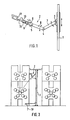
- a robotic arm 2 can be moved back and forth in the direction of the axis of the guide 1 and is pivotable about this axis on a vertical guide 1 and can be pivoted vertically by means of a first joint 3 attached to the guide 1 and which is divided by a second joint 4, a third joint 5 and a fourth joint 6 into a first section 7, a second section 8, a third section 9 and a fourth section 10, the fourth arm section 10 corresponding to the intended handling designed handling head 11.
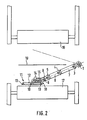
- Fig. 2 it is shown that the device of Fig. 1 is attached to the vertical guide 1 such that it can operate both a plate cylinder 17 of a left printing unit and a plate cylinder 16 of a right printing unit at approximately the same angular deflection.
- the vertical guide is placed so that when the robot arm 2 is in the working position, there can be no contact with a printing material web 19 running between the adjacent printing units.
- the arm 2 In order to move the arm 2 from the left plate cylinder 17 to the right plate cylinder 16, the arm 2 can either be placed vertically as a whole or additionally deflected in a first joint 4 by almost 180 °. Thus, even during the swiveling movement during which the arm 2 turns from one printing unit to the other, there is no danger of contact with the web 19.
- the robot arm 2 is so long that it can reach the plate cylinder furthest away from the vertical guide 1 in the extended position.
- the robot arm 2 has in its fourth arm section 10 a handling head 11, which essentially consists of a suction rod 12 with suction cups 13 for gripping and holding the pressure plate and a rotary guide rod 14 attached to the suction rod 12, which is rotatably mounted in a sleeve-like arm element 15, consists.
- the handling head 11 has a device 18 which is suitably designed for loading the plate cylinders 16, 17 and which can be used to insert and fix the printing plate on the plate cylinder 16 or 17 and to detach the printing plate from the plate cylinder alone or together with one on the plate cylinder 16 or 17 provided device.
- the device 18 can be designed, for example, as a mechanically actuable claw.
- the joint 5 enables the suction rod 12 with the suction cups 13 to be brought into the horizontal independently of the spatial position of the other arm sections.
- the joint 6 it is possible to set up the rotary guide rod 14 parallel to the axis of the plate cylinder 16 or 17. With the rotary guide rod and their storage in the arm element 15 allows the pressure plate to be adapted to the cylinder periphery.
- the movements of the sections 7 to 10 of the robot arm 2 are hydraulically controlled in a manner known per se.
- the actuating cylinders, hydraulic lines and fastening elements required for this, as well as the hydraulic fluid reservoir and the associated control device are not shown in FIGS. 1 to 3 for the sake of clarity.
- a suitable interplay of the movements of the joints 3, 4 and 5 and the rotation of the rotary guide rod 14 enables the arm 2 to be set up in such a way that the plate cylinder facing the vertical guide 1 can be loaded.
- FIG. 3 shows, in a schematic side view, two adjacent printing units with a printing material web guided vertically in sections between the two printing units and a handling device according to the invention arranged between the two printing units.
- the plate cylinders of the two printing units are operated by the handling device without the movements of the robot arm 2 or the loading of the plate cylinders 16 and 17 being restricted by the course of the printing material web.
Landscapes
- Supply, Installation And Extraction Of Printed Sheets Or Plates (AREA)
Abstract
- 1. Handhabungsvorrichtung
- 2.1. Bekannte Handhabungsvorrichtungen zum Beschicken von Plattenzylindern von Rotationsdruckmaschinen können entweder nur ein einziges Druckwerk bedienen oder beanspruchen soviel Platz, daß sie nur bei kleineren Druckmaschinen Verwendung finden.
- 2.2. Die erfindungsgemäße Handhabungsvorrichtung weist einen an einer Führung (1) vertikal bewegbar und schwenkbar angebrachten Roboterarm (2) auf, der durch wenigstens ein Gelenk (3 bis 6) in Armabschnitte (7 bis 10) gegliedert ist und der an dem von der Führung (1) am weitesten entfernten Armabschnitt (10) einen Handhabungskopf (11) aufweist.
- 2.3. Die Erfindung ist auf alle Rollenrotationsdruckmaschinen anwendbar.
Description
- Die vorliegende Erfindung betrifft eine Handhabungsvorrichtung zum Beschicken von Plattenzylindern für Druckmaschinen und insbesondere eine solche Vorrichtung für Rollenrotationsdruckmaschinen.
- Aus der US-Patentschrift 4,727,807 ist eine Vorrichtung zur automatischen Montage und Demontage von Druckplatten in einer Rotationsdruckmaschine bekannt. Diese Vorrichtung ist mit einem Plattenmagazin einschließlich einer Plattenentnahmevorrichtung versehen und wird vor einem Druckwerk plaziert. Mit dem über eine Parallelogrammführung aufgehängten Arm und der daran angebrachten mechanischen Hand kann die Vorrichtung in ihrer rückwärtigen Stellung eine aus dem Plattenmagazin entnommene Druckplatte erfassen und diese in ihrer vorderen Stellung auf den Zylinder aufbringen. Da die Vorrichtung an einem auf dem Boden befestigten Hauptteil oder an einem Druckwerksgestell nichtdrehbar angebracht ist, kann sie nur ein einziges Druckwerk bedienen. Damit kann der von einer solchen Anordnung benötigte Platz nur bei kleinen Rotationsdruckmaschinen, insbesondere bei solchen mit einem einzigen Druckwerk, inkaufgenommen werden.
- Aus der japanischen Patentschrift JP 60-73850 ist eine auf am Boden verlegten Schienen bewegbare oder an einem Druckwerksgestell angebrachte Vorrichtung zum Montieren und Demontieren von Druckplatten in einer Rotationsdruckmaschine bekannt. Bei dieser Vorrichtung ist der die mechanische Hand tragende, horizontal verlaufende Arm in Richtung seiner Längsachse beweglich gelagert, entlang einer senkrecht verlaufenden Spindel höhenverstellbar und um die Achse der Spindel drehbar angebracht. Dadurch eignet sich diese Vorrichtung für eine wahlweise Bedienung zweier nebeneinander angeordneter Druckwerke. Nachteilig ist jedoch der durch die horizontale Beweglichkeit bedingte Platzbedarf der Vorrichtung.
- Aufgabe der Erfindung ist es, eine Handhabungsvorrichtung zu schaffen, welche die Plattenzylinder benachbarter Druckwerke bedienen kann, ohne dabei durch den Verlauf der durch die Druckwerke geführten wenigstens einen Bedruckstoffbahn in der Beweglichkeit eingeschränkt zu sein.
- Diese Aufgabe wird durch eine Handhabungsvorrichtung mit den Merkmalen des Patentanspruchs 1 gelöst.
- Vorteilhafte Weiterbildungen der erfindungsgemäßen Vorrichtung sind Gegenstand von Unteransprüchen.
- Weitere Merkmale und Zweckmäßigkeiten der Erfindung ergeben sich aus der Beschreibung eines Ausführungsbeispiels anhand der Figuren. Von den Figuren zeigen:
- Fig. 1
- eine schematische Darstellung einer Handhabungsvorrichtung in einer erfindungsgemäßen Ausführungsform;
- Fig. 2
- eine schematische Draufsicht auf die in Fig. 1 gezeigte Vorrichtung in Arbeitsstellung zwischen zwei Druckwerken und
- Fig. 3
- eine Seitenansicht zweier benachbarter Druckwerke mit einer dazwischen angeordneten, der in Fig. 1 dargestellten Vorrichtung entsprechenden Vorrichtung.
- Wie in Fig. 1 dargestellt ist, ist an einer vertikalen Führung 1 ein Roboterarm 2 in Richtung der Achse der Führung 1 hin- und herbewegbar und um diese Achse schwenkbar angebracht, der mittels eines an der Führung 1 angebrachten ersten Gelenks 3 vertikal geschwenkt werden kann und der durch ein zweites Gelenk 4, ein drittes Gelenk 5 und ein viertes Gelenk 6 in einen ersten Abschnitt 7, einen zweiten Abschnitt 8, einen dritten Abschnitt 9 und einen vierten Abschnitt 10 gegliedert ist, wobei der vierte Armabschnitt 10 einen der vorgesehenen Handhabung entsprechend ausgelegten Handhabungskopf 11 aufweist.
- In Fig. 2 ist gezeigt, daß die Vorrichtung von Fig. 1 an der vertikalen Führung 1 derart angebracht ist, daß sie bei ungefähr gleichem Winkelausschlag sowohl einen Plattenzylinder 17 eines linken Druckwerks wie einen Plattenzylinder 16 eines rechten Druckwerks bedienen kann. Die vertikale Führung ist dabei so plaziert, daß bei Arbeitsstellung des Roboterarms 2 keine Berührung mit einer zwischen den benachbarten Druckwerken laufenden Bedruckstoffbahn 19 stattfinden kann.
- Um den Arm 2 vom linken Plattenzylinder 17 zum rechten Plattenzylinder 16 zu bewegen, kann der Arm 2 entweder als Ganzes senkrecht gestellt oder dabei zusätzlich in einem ersten Gelenk 4 noch um nahezu 180° umgelenkt werden. Damit ist auch bei der Schwenkbewegung, während der sich der Arm 2 vom einen dem anderen Druckwerk zuwendet, die Gefahr einer Berührung mit der Bahn 19 nicht gegeben. Der Roboterarm 2 ist so lang, daß er den von der vertikalen Führung 1 am weitesten entfernt liegenden Plattenzylinder in ausgestreckter Position erreichen kann.
- Der Roboterarm 2 weist in seinem vierten Armabschnitt 10 einen Handhabungskopf 11 auf, der im wesentlichen aus einer Saugstange 12 mit Saugnäpfen 13 zum Erfassen und Festhalten der Druckplatte und einer an der Saugstange 12 angebrachten Drehführungsstange 14, die in einem hülsenartigen Armelement 15 drehbar gelagert ist, besteht. Weiterhin weist der Handhabungskopf 11 eine für die Beschickung der Plattenzylinder 16, 17 geeignet ausgebildete Vorrichtung 18 auf, die das Einsetzen und Befestigen der Druckplatte auf dem Plattenzylinder 16 bzw. 17 sowie das Lösen der Druckplatte vom Plattenzylinder allein oder zusammen mit einer am Plattenzylinder 16 bzw. 17 vorgesehenen Vorrichtung bewirkt. Die Vorrichtung 18 kann zum Beispiel als mechanisch betätigbare Klaue ausgebildet sein. Das Gelenk 5 ermöglicht, daß die Saugstange 12 mit den Saugnäpfen 13 unabhängig von der räumlichen Stellung der anderen Armabschnitte in die Waagrechte gebracht werden kann. Mit dem Gelenk 6 ist es möglich, die Drehführungsstange 14 zum Plattenzylinder 16 bzw. 17 achsparallel einrichten zu können. Mit der Drehführungsstange und deren Lagerung im Armelement 15 ist eine Anpassung der Druckplatte an die Zylinderperipherie möglich.
- Die Bewegungen der Abschnitte 7 bis 10 des Roboterarms 2 werden in an sich bekannter Weise hydraulisch gesteuert. Die dafür erforderlichen Stellzylinder, Hydraulikleitungen und Befestigungselemente, sowie die Hydraulikflüssigkeitsvorratsbehälter und die zugehörige Steuervorrichtung sind in den Fig. 1 bis 3 der besseren Übersichtlichkeit halber nicht dargestellt. Ein geeignetes Zusammenspiel der Bewegungen der Gelenke 3, 4 und 5 sowie der Drehung der Drehführungsstange 14 ermöglicht, den Arm 2 so einzurichten, daß eine Beschickung der der Vertikalführung 1 zugewandten Plattenzylinder erfolgen kann.
- Mit einer wie vorstehend beschrieben aufgebauten Handhabungsvorrichtung ist es möglich, das Beschicken von Plattenzylindern einer Druckmaschine, wie zum Beispiel einer im Zeitungsdruck verwendeten Rotationsdruckmaschine, das sehr arbeitsintensiv ist und in der Regel unter einem gewissen Zeitdruck erfolgt, da die Druckplatten aus Aktualitätsgründen teilweise erst kurz vor Druckbeginn fertiggestellt werden, derart zu verbessern und insbesondere wenigstens teilweise automatisierbar zu gestalten, daß nicht nur Zeit und Personal eingespart werden können, sondern daß der spätestmögliche Anliefertermin für die Druckplatten noch weiter hinausgezogen werden kann.
- Fig. 3 zeigt in einer schematischen Seitenansicht zwei benachbart angeordnete Druckwerke mit einer streckenweise zwischen den beiden Druckwerken vertikal geführten Bedruckstoffbahn und einer zwischen den beiden Druckwerken angeordneten erfindungsgemäßen Handhabungsvorrichtung. Die Plattenzylinder der beiden Druckwerke werden von der Handhabungsvorrichtung bedient, ohne daß die Bewegungen des Roboterarms 2 oder überhaupt das Beschicken der Plattenzylinder 16 und 17 durch den Verlauf der Bedruckstoffbahn eingeschränkt werden.
Claims (7)
- Handhabungsvorrichtung zum Beschicken von Plattenzylindern für Rotationsdruckmaschinen mit einem an einer vertikalen Führung (1) in Richtung der Achse der Führung (1) hin- und herbewegbar und um diese Achse schwenkbar angebrachten Roboterarm (2) und einem Handhabungskopf (11), wobei die Führung(1) zwischen zu bedienenden Plattenzylindern (16, 17) zweier benachbarter Druckwerke angeordnet ist.
- Handhabungsvorrichtung nach Anspruch 1, dadurch gekennzeichnet, daß der Roboterarm (2) mittels eines an der Führung (1) angebrachten ersten Gelenks (3) vertikal geschwenkt werden kann.
- Handhabungsvorrichtung nach Anspruch 1 oder 2, dadurch gekennzeichnet, daß der Roboterarm (2) durch wenigstens ein Gelenk (3 bis 6) in Armabschnitte (7 bis 10) gegliedert ist.
- Handhabungsvorrichtung nach Anspruch 2, dadurch gekennzeichnet, daß der Roboterarm (2) durch ein zweites Gelenk (4), ein drittes Gelenk (5) und ein viertes Gelenk (6) in einen ersten Armabschnitt (7), einen zweiten Armabschnitt (8), einen dritten Armabschnitt (9) und einen vierten Armabschnitt (10) gegliedert ist.
- Handhabungsvorrichtung nach Anspruch 3 oder 4, dadurch gekennzeichnet, daß der Handhabungskopf (11) an dem von der Führung (1) am weitesten entfernten Armabschnitt (10) angebracht ist.
- Handhabungsvorrichtung nach einem der Ansprüche 1 bis 5, dadurch gekennzeichnet, daß der Handhabungskopf (11) eine Vorrichtung (18) aufweist, die allein oder zusammen mit einer am Plattenzylinder vorgesehenen Vorrichtung das Befestigen der Druckplatte am und das Lösen der Druckplatte vom Plattenzylinder (16, 17) bewirkt.
- Handhabungsvorrichtung nach einem der Ansprüche 1 bis 6, gekennzeichnet durch eine hydraulisch wirkende Vorrichtung zum Betätigen der Armabschnitte (7, 8, 9, 10) des Roboterarms (2).
Applications Claiming Priority (2)
| Application Number | Priority Date | Filing Date | Title |
|---|---|---|---|
| DE3940449 | 1989-12-07 | ||
| DE3940449A DE3940449A1 (de) | 1989-12-07 | 1989-12-07 | Handhabungsvorrichtung |
Publications (3)
| Publication Number | Publication Date |
|---|---|
| EP0431364A2 true EP0431364A2 (de) | 1991-06-12 |
| EP0431364A3 EP0431364A3 (en) | 1991-11-27 |
| EP0431364B1 EP0431364B1 (de) | 1994-07-13 |
Family
ID=6394981
Family Applications (1)
| Application Number | Title | Priority Date | Filing Date |
|---|---|---|---|
| EP90121867A Expired - Lifetime EP0431364B1 (de) | 1989-12-07 | 1990-11-15 | Handhabungsvorrichtung |
Country Status (5)
| Country | Link |
|---|---|
| US (1) | US5127322A (de) |
| EP (1) | EP0431364B1 (de) |
| JP (1) | JPH03184849A (de) |
| CA (1) | CA2027746C (de) |
| DE (2) | DE3940449A1 (de) |
Cited By (7)
| Publication number | Priority date | Publication date | Assignee | Title |
|---|---|---|---|---|
| US5595120A (en) * | 1995-03-31 | 1997-01-21 | Heidelberger Druckmaschinen Ag | Device for feeding printing forms to and changing them on a printing form cylinder |
| EP1652667A2 (de) | 2004-10-26 | 2006-05-03 | Maschinenfabrik Wifag | Druckformmanipulator |
| DE102007028955B3 (de) * | 2007-06-22 | 2008-08-21 | Koenig & Bauer Aktiengesellschaft | Verfahren zum Betreiben einer Druckeinheit mit mindestens einem Druckwerk |
| EP2017081A3 (de) * | 2007-07-14 | 2010-11-03 | manroland AG | Handhabungsvorrichtung einer Druckmaschine |
| EP2266798A1 (de) * | 2004-04-29 | 2010-12-29 | Goss Graphic Systems Limited | Druckplatteneinheit und Druckmaschine |
| US8087356B2 (en) | 2006-11-22 | 2012-01-03 | Man Roland Druckmaschinen Ag | Handling device of a printing press |
| US8505452B2 (en) | 2004-04-29 | 2013-08-13 | Goss Graphic Systems Limited | Printing press including plate support member and plate loading module |
Families Citing this family (17)
| Publication number | Priority date | Publication date | Assignee | Title |
|---|---|---|---|---|
| JP2700364B2 (ja) * | 1991-06-19 | 1998-01-21 | 株式会社小森コーポレーション | 印刷機の刷版交換装置 |
| DE4214047A1 (de) * | 1992-04-29 | 1993-11-04 | Heidelberger Druckmasch Ag | Halteeinrichtung fuer eine zu verschiebende platte |
| DE4214049A1 (de) * | 1992-04-29 | 1993-11-04 | Heidelberger Druckmasch Ag | Vorrichtung zum zufuehren einer druckplatte zu einem plattenzylinder einer druckmaschine |
| DE4309658C1 (de) * | 1993-03-25 | 1994-10-27 | Roland Man Druckmasch | Vorrichtung zum automatischen Wechseln von Druckplatten bei Bogenoffsetdruckmaschinen mit mehreren Druckwerken |
| JP2724668B2 (ja) * | 1993-09-24 | 1998-03-09 | 株式会社東京機械製作所 | 刷版配送装置 |
| DE19549707B4 (de) * | 1994-11-16 | 2005-03-03 | Kabushiki Kaisha Tokyo Kikai Seisakusho | Apparat und Verfahren zum Verriegeln einer Druckplatte einer Rotationsdruckpresse |
| JP2691974B2 (ja) * | 1994-11-16 | 1997-12-17 | 株式会社東京機械製作所 | 刷版支持装置及び刷版着脱装置 |
| DE19531024B4 (de) * | 1994-11-16 | 2005-01-27 | Kabushiki Kaisha Tokyo Kikai Seisakusho | Vorrichtung und Verfahren zum Anbringen einer Druckplatte auf einem Plattenzylinder einer Rotationsdruckpresse |
| DE4442265A1 (de) * | 1994-11-28 | 1996-05-30 | Roland Man Druckmasch | Transportsystem zum Transport von Druckformen |
| US5778779A (en) | 1996-01-04 | 1998-07-14 | Heidelberger Druckmaschinen Ag | Printing unit and register mechanism for mounting a printing sleeve |
| SG104259A1 (en) | 1996-06-28 | 2004-06-21 | Ideas To Market Lp | High density composite material |
| US6772688B2 (en) | 2002-04-05 | 2004-08-10 | Agfa Corporation | Imaging system with automated plate locating mechanism and method for loading printing plate |
| US6729234B2 (en) | 2002-04-05 | 2004-05-04 | Agfa Corporation | Actuation system in an imaging system |
| DE102004052021A1 (de) * | 2004-10-26 | 2006-05-04 | Maschinenfabrik Wifag | Druckformmanipulator |
| DE102004052020B8 (de) * | 2004-10-26 | 2013-07-04 | Wifag Maschinenfabrik Ag | Druckformmanipulator |
| CN102173198B (zh) * | 2011-01-21 | 2014-07-16 | 天津长荣印刷设备股份有限公司 | 一种用于清叼口的连杆开牙装置及其工作方法 |
| JP7118786B2 (ja) * | 2018-07-17 | 2022-08-16 | リョービMhiグラフィックテクノロジー株式会社 | 印刷機 |
Family Cites Families (11)
| Publication number | Priority date | Publication date | Assignee | Title |
|---|---|---|---|---|
| CH610241A5 (de) * | 1977-02-07 | 1979-04-12 | Sisenca Sa | |
| DE3104562A1 (de) * | 1981-02-10 | 1982-09-02 | Koenig & Bauer AG, 8700 Würzburg | "vorrichtung zum fuehren einer papierbahn in einer druckeinheit einer rollenrotationsdruckmaschine" |
| DE3138484A1 (de) * | 1981-09-28 | 1983-04-14 | Deutsche Gesellschaft für Wiederaufarbeitung von Kernbrennstoffen mbH, 3000 Hannover | "verfahren zur instandhaltung von vorrichtungen und bauteilen in heissen zellen, insbesondere von wiederaufarbeitungsanlagen fuer abgebrannte kernbrennstoffe, und vorrichtung zur durchfuehrung des verfahrens |
| EP0100778B1 (de) * | 1982-08-10 | 1986-06-11 | Mitsubishi Jukogyo Kabushiki Kaisha | Vorrichtung zum automatischen Auswechseln von Druckplatten |
| DE3239580A1 (de) * | 1982-10-26 | 1984-04-26 | Rotaprint Gmbh, 1000 Berlin | Folienwechsler fuer offset-druckmaschinen |
| JPS59165659A (ja) * | 1983-03-11 | 1984-09-18 | Mitsubishi Heavy Ind Ltd | 印刷機の刷版自動着脱システム |
| JPS6073850A (ja) * | 1983-09-26 | 1985-04-26 | Tokyo Kikai Seisakusho:Kk | 輪転機における刷版自動着脱装置 |
| JPS6219458A (ja) * | 1985-07-19 | 1987-01-28 | Akiyama Insatsuki Seizo Kk | オフセツト印刷機の版着脱装置 |
| US4727807A (en) * | 1985-09-30 | 1988-03-01 | Tokyo Kikai Seisakusho | Apparatus for automatically mounting and removing printing plates in rotary printing press |
| JPH07115462B2 (ja) * | 1988-01-06 | 1995-12-13 | 三菱重工業株式会社 | 刷版の版胴への着脱ロボット用ハンド |
| JPH0673850A (ja) * | 1992-08-24 | 1994-03-15 | Matsushita Electric Works Ltd | 採光窓装置 |
-
1989
- 1989-12-07 DE DE3940449A patent/DE3940449A1/de active Granted
-
1990
- 1990-10-12 US US07/596,947 patent/US5127322A/en not_active Expired - Fee Related
- 1990-10-16 CA CA002027746A patent/CA2027746C/en not_active Expired - Fee Related
- 1990-11-15 EP EP90121867A patent/EP0431364B1/de not_active Expired - Lifetime
- 1990-11-15 DE DE59006426T patent/DE59006426D1/de not_active Expired - Lifetime
- 1990-11-28 JP JP2323408A patent/JPH03184849A/ja active Pending
Cited By (9)
| Publication number | Priority date | Publication date | Assignee | Title |
|---|---|---|---|---|
| US5595120A (en) * | 1995-03-31 | 1997-01-21 | Heidelberger Druckmaschinen Ag | Device for feeding printing forms to and changing them on a printing form cylinder |
| EP2266798A1 (de) * | 2004-04-29 | 2010-12-29 | Goss Graphic Systems Limited | Druckplatteneinheit und Druckmaschine |
| US8505452B2 (en) | 2004-04-29 | 2013-08-13 | Goss Graphic Systems Limited | Printing press including plate support member and plate loading module |
| EP1652667A2 (de) | 2004-10-26 | 2006-05-03 | Maschinenfabrik Wifag | Druckformmanipulator |
| EP1652667A3 (de) * | 2004-10-26 | 2006-07-12 | Maschinenfabrik Wifag | Druckformmanipulator |
| US8087356B2 (en) | 2006-11-22 | 2012-01-03 | Man Roland Druckmaschinen Ag | Handling device of a printing press |
| DE102007028955B3 (de) * | 2007-06-22 | 2008-08-21 | Koenig & Bauer Aktiengesellschaft | Verfahren zum Betreiben einer Druckeinheit mit mindestens einem Druckwerk |
| EP2017081A3 (de) * | 2007-07-14 | 2010-11-03 | manroland AG | Handhabungsvorrichtung einer Druckmaschine |
| US8434406B2 (en) | 2007-07-14 | 2013-05-07 | Manroland Ag | Handling device of a printing press |
Also Published As
| Publication number | Publication date |
|---|---|
| CA2027746A1 (en) | 1991-06-08 |
| DE3940449A1 (de) | 1991-06-13 |
| DE59006426D1 (de) | 1994-08-18 |
| US5127322A (en) | 1992-07-07 |
| EP0431364A3 (en) | 1991-11-27 |
| CA2027746C (en) | 1994-05-10 |
| JPH03184849A (ja) | 1991-08-12 |
| DE3940449C2 (de) | 1991-10-31 |
| EP0431364B1 (de) | 1994-07-13 |
Similar Documents
| Publication | Publication Date | Title |
|---|---|---|
| EP0431364B1 (de) | Handhabungsvorrichtung | |
| EP0106056B1 (de) | Vorrichtung insbesondere zum Be- und Entladen einer Bearbeitungsmaschine für Blech | |
| EP0238804B1 (de) | Vorrichtung zum Aufspannen von biegsamen Druckplatten auf dem Plattenzylinder von Rotationsdruckmaschinen | |
| EP0279394A2 (de) | Haltevorrichtung für das Aufbringen einer Hülse auf einen Zylinder | |
| DE4442574C2 (de) | Verfahren und Vorrichtung zur Bereitstellung einer Druckplatte | |
| DE2359313C2 (de) | Gerät zum Abbrechen einer Betonwand od.dgl. | |
| DE4424903C2 (de) | Vorrichtung zur Montage, Demontage und Transport von leicht biegbaren, bogenförmigen Gegenständen mit Einhängeabkantungen | |
| DE3515729C2 (de) | ||
| AT403812B (de) | Maschine zum anpressen von schwellenankern | |
| WO1995019262A1 (de) | Vorrichtung zur montage, demontage und transport von leicht biegbaren, bogenförmigen gegenständen mit einhängeabkantungen | |
| DE2633605C2 (de) | Einrichtung zum Verlegen von Querschwellen eines Gleises | |
| DE102015221762A1 (de) | Vorrichtung zum Anstellen einer Stauchwalze eines Stauchgerüsts | |
| DE2213316A1 (de) | Anlegezylinder | |
| EP1927474B1 (de) | Druckmachine mit einer Handhabungsvorrichtung | |
| DE2619261C3 (de) | Fädelvorrichtung für eine Drahterodiermaschine | |
| DE4030864C2 (de) | ||
| EP1530514B1 (de) | Verfahren zum montieren eines aufzugs auf einem zylinder einer druckmaschine | |
| CH651501A5 (en) | Sheet-fed rotary printing machine having at least one printing unit | |
| DE10338374A1 (de) | Vorrichtung zum Zuführen von Druckplatten zu einer Druckplattenwechsel-Einrichtung | |
| DE3719337A1 (de) | Greifer fuer einen roboter | |
| DE19512421C2 (de) | Einrichtung zum Reinigen mehrerer Zylinder | |
| DE3742247C2 (de) | Armaturenträger zur Aufnahme von Walzarmaturen | |
| DE2636718C2 (de) | Vorrichtung zum Pressen und Vulkanisieren von Fördergurten | |
| CH683157A5 (de) | Einrichtung zum Biegen von Metallblechen und Vorrichtung zum Manipulieren von Metallblech. | |
| DE1527943C3 (de) | Anschlageinrichtung an Abkantpressen |
Legal Events
| Date | Code | Title | Description |
|---|---|---|---|
| PUAI | Public reference made under article 153(3) epc to a published international application that has entered the european phase |
Free format text: ORIGINAL CODE: 0009012 |
|
| AK | Designated contracting states |
Kind code of ref document: A2 Designated state(s): CH DE FR GB IT LI SE |
|
| PUAL | Search report despatched |
Free format text: ORIGINAL CODE: 0009013 |
|
| AK | Designated contracting states |
Kind code of ref document: A3 Designated state(s): CH DE FR GB IT LI SE |
|
| 17P | Request for examination filed |
Effective date: 19911107 |
|
| 17Q | First examination report despatched |
Effective date: 19930915 |
|
| ITF | It: translation for a ep patent filed | ||
| GRAA | (expected) grant |
Free format text: ORIGINAL CODE: 0009210 |
|
| AK | Designated contracting states |
Kind code of ref document: B1 Designated state(s): CH DE FR GB IT LI SE |
|
| GBT | Gb: translation of ep patent filed (gb section 77(6)(a)/1977) |
Effective date: 19940715 |
|
| REF | Corresponds to: |
Ref document number: 59006426 Country of ref document: DE Date of ref document: 19940818 |
|
| ET | Fr: translation filed | ||
| EAL | Se: european patent in force in sweden |
Ref document number: 90121867.7 |
|
| PLBE | No opposition filed within time limit |
Free format text: ORIGINAL CODE: 0009261 |
|
| STAA | Information on the status of an ep patent application or granted ep patent |
Free format text: STATUS: NO OPPOSITION FILED WITHIN TIME LIMIT |
|
| 26N | No opposition filed | ||
| PGFP | Annual fee paid to national office [announced via postgrant information from national office to epo] |
Ref country code: GB Payment date: 19961014 Year of fee payment: 7 |
|
| PGFP | Annual fee paid to national office [announced via postgrant information from national office to epo] |
Ref country code: CH Payment date: 19961023 Year of fee payment: 7 |
|
| PGFP | Annual fee paid to national office [announced via postgrant information from national office to epo] |
Ref country code: SE Payment date: 19961024 Year of fee payment: 7 |
|
| PG25 | Lapsed in a contracting state [announced via postgrant information from national office to epo] |
Ref country code: GB Free format text: LAPSE BECAUSE OF NON-PAYMENT OF DUE FEES Effective date: 19971115 |
|
| PG25 | Lapsed in a contracting state [announced via postgrant information from national office to epo] |
Ref country code: SE Free format text: LAPSE BECAUSE OF NON-PAYMENT OF DUE FEES Effective date: 19971116 |
|
| PG25 | Lapsed in a contracting state [announced via postgrant information from national office to epo] |
Ref country code: CH Free format text: LAPSE BECAUSE OF NON-PAYMENT OF DUE FEES Effective date: 19971130 Ref country code: LI Free format text: LAPSE BECAUSE OF NON-PAYMENT OF DUE FEES Effective date: 19971130 |
|
| GBPC | Gb: european patent ceased through non-payment of renewal fee |
Effective date: 19971115 |
|
| REG | Reference to a national code |
Ref country code: CH Ref legal event code: PL |
|
| EUG | Se: european patent has lapsed |
Ref document number: 90121867.7 |
|
| PGFP | Annual fee paid to national office [announced via postgrant information from national office to epo] |
Ref country code: FR Payment date: 20001101 Year of fee payment: 11 |
|
| PG25 | Lapsed in a contracting state [announced via postgrant information from national office to epo] |
Ref country code: FR Free format text: LAPSE BECAUSE OF NON-PAYMENT OF DUE FEES Effective date: 20020730 |
|
| REG | Reference to a national code |
Ref country code: FR Ref legal event code: ST |
|
| REG | Reference to a national code |
Ref country code: FR Ref legal event code: ST |
|
| PG25 | Lapsed in a contracting state [announced via postgrant information from national office to epo] |
Ref country code: IT Free format text: LAPSE BECAUSE OF NON-PAYMENT OF DUE FEES;WARNING: LAPSES OF ITALIAN PATENTS WITH EFFECTIVE DATE BEFORE 2007 MAY HAVE OCCURRED AT ANY TIME BEFORE 2007. THE CORRECT EFFECTIVE DATE MAY BE DIFFERENT FROM THE ONE RECORDED. Effective date: 20051115 |
|
| PGFP | Annual fee paid to national office [announced via postgrant information from national office to epo] |
Ref country code: DE Payment date: 20091120 Year of fee payment: 20 |
|
| PG25 | Lapsed in a contracting state [announced via postgrant information from national office to epo] |
Ref country code: DE Free format text: LAPSE BECAUSE OF EXPIRATION OF PROTECTION Effective date: 20101115 |