EP0430794B1 - Fauteuil roulant démontable et sac pour le transport d'un tel fauteuil après son démontage - Google Patents
Fauteuil roulant démontable et sac pour le transport d'un tel fauteuil après son démontage Download PDFInfo
- Publication number
- EP0430794B1 EP0430794B1 EP90403358A EP90403358A EP0430794B1 EP 0430794 B1 EP0430794 B1 EP 0430794B1 EP 90403358 A EP90403358 A EP 90403358A EP 90403358 A EP90403358 A EP 90403358A EP 0430794 B1 EP0430794 B1 EP 0430794B1
- Authority
- EP
- European Patent Office
- Prior art keywords
- wheelchair according
- wheel
- inner ring
- wheels
- ring
- Prior art date
- Legal status (The legal status is an assumption and is not a legal conclusion. Google has not performed a legal analysis and makes no representation as to the accuracy of the status listed.)
- Expired - Lifetime
Links
- 239000011248 coating agent Substances 0.000 claims description 3
- 238000000576 coating method Methods 0.000 claims description 3
- 230000000717 retained effect Effects 0.000 claims description 2
- 238000005096 rolling process Methods 0.000 claims 1
- 230000005540 biological transmission Effects 0.000 description 4
- 210000000078 claw Anatomy 0.000 description 4
- 230000000295 complement effect Effects 0.000 description 4
- 239000000470 constituent Substances 0.000 description 4
- 241000239290 Araneae Species 0.000 description 2
- 239000004744 fabric Substances 0.000 description 2
- 239000000463 material Substances 0.000 description 2
- 235000008612 Gnetum gnemon Nutrition 0.000 description 1
- 240000000018 Gnetum gnemon Species 0.000 description 1
- 230000000903 blocking effect Effects 0.000 description 1
- 238000010586 diagram Methods 0.000 description 1
- 230000000694 effects Effects 0.000 description 1
- 230000005611 electricity Effects 0.000 description 1
- 239000002828 fuel tank Substances 0.000 description 1
- 238000003780 insertion Methods 0.000 description 1
- 230000037431 insertion Effects 0.000 description 1
- 238000009434 installation Methods 0.000 description 1
- 238000000034 method Methods 0.000 description 1
- 230000000877 morphologic effect Effects 0.000 description 1
- 230000002093 peripheral effect Effects 0.000 description 1
- 230000003014 reinforcing effect Effects 0.000 description 1
- 230000000284 resting effect Effects 0.000 description 1
Images


Classifications
-
- A—HUMAN NECESSITIES
- A61—MEDICAL OR VETERINARY SCIENCE; HYGIENE
- A61G—TRANSPORT, PERSONAL CONVEYANCES, OR ACCOMMODATION SPECIALLY ADAPTED FOR PATIENTS OR DISABLED PERSONS; OPERATING TABLES OR CHAIRS; CHAIRS FOR DENTISTRY; FUNERAL DEVICES
- A61G5/00—Chairs or personal conveyances specially adapted for patients or disabled persons, e.g. wheelchairs
- A61G5/04—Chairs or personal conveyances specially adapted for patients or disabled persons, e.g. wheelchairs motor-driven
- A61G5/041—Chairs or personal conveyances specially adapted for patients or disabled persons, e.g. wheelchairs motor-driven having a specific drive-type
- A61G5/045—Rear wheel drive
-
- A—HUMAN NECESSITIES
- A61—MEDICAL OR VETERINARY SCIENCE; HYGIENE
- A61G—TRANSPORT, PERSONAL CONVEYANCES, OR ACCOMMODATION SPECIALLY ADAPTED FOR PATIENTS OR DISABLED PERSONS; OPERATING TABLES OR CHAIRS; CHAIRS FOR DENTISTRY; FUNERAL DEVICES
- A61G5/00—Chairs or personal conveyances specially adapted for patients or disabled persons, e.g. wheelchairs
- A61G5/02—Chairs or personal conveyances specially adapted for patients or disabled persons, e.g. wheelchairs propelled by the patient or disabled person
- A61G5/028—Special adaptations or provisions on hand rim, e.g. for facilitating gripping
-
- A—HUMAN NECESSITIES
- A61—MEDICAL OR VETERINARY SCIENCE; HYGIENE
- A61G—TRANSPORT, PERSONAL CONVEYANCES, OR ACCOMMODATION SPECIALLY ADAPTED FOR PATIENTS OR DISABLED PERSONS; OPERATING TABLES OR CHAIRS; CHAIRS FOR DENTISTRY; FUNERAL DEVICES
- A61G5/00—Chairs or personal conveyances specially adapted for patients or disabled persons, e.g. wheelchairs
- A61G5/08—Chairs or personal conveyances specially adapted for patients or disabled persons, e.g. wheelchairs foldable
- A61G5/0808—Chairs or personal conveyances specially adapted for patients or disabled persons, e.g. wheelchairs foldable characterised by a particular folding direction
- A61G5/0816—Chairs or personal conveyances specially adapted for patients or disabled persons, e.g. wheelchairs foldable characterised by a particular folding direction folding side to side, e.g. reducing or expanding the overall width of the wheelchair
- A61G5/0825—Chairs or personal conveyances specially adapted for patients or disabled persons, e.g. wheelchairs foldable characterised by a particular folding direction folding side to side, e.g. reducing or expanding the overall width of the wheelchair comprising a scissor-type frame, e.g. having pivoting cross bars for enabling folding
-
- A—HUMAN NECESSITIES
- A61—MEDICAL OR VETERINARY SCIENCE; HYGIENE
- A61G—TRANSPORT, PERSONAL CONVEYANCES, OR ACCOMMODATION SPECIALLY ADAPTED FOR PATIENTS OR DISABLED PERSONS; OPERATING TABLES OR CHAIRS; CHAIRS FOR DENTISTRY; FUNERAL DEVICES
- A61G5/00—Chairs or personal conveyances specially adapted for patients or disabled persons, e.g. wheelchairs
- A61G5/10—Parts, details or accessories
- A61G5/1054—Large wheels, e.g. higher than the seat portion
-
- A—HUMAN NECESSITIES
- A61—MEDICAL OR VETERINARY SCIENCE; HYGIENE
- A61G—TRANSPORT, PERSONAL CONVEYANCES, OR ACCOMMODATION SPECIALLY ADAPTED FOR PATIENTS OR DISABLED PERSONS; OPERATING TABLES OR CHAIRS; CHAIRS FOR DENTISTRY; FUNERAL DEVICES
- A61G5/00—Chairs or personal conveyances specially adapted for patients or disabled persons, e.g. wheelchairs
- A61G5/10—Parts, details or accessories
- A61G5/12—Rests specially adapted therefor, e.g. for the head or the feet
- A61G5/125—Rests specially adapted therefor, e.g. for the head or the feet for arms
-
- A—HUMAN NECESSITIES
- A61—MEDICAL OR VETERINARY SCIENCE; HYGIENE
- A61G—TRANSPORT, PERSONAL CONVEYANCES, OR ACCOMMODATION SPECIALLY ADAPTED FOR PATIENTS OR DISABLED PERSONS; OPERATING TABLES OR CHAIRS; CHAIRS FOR DENTISTRY; FUNERAL DEVICES
- A61G5/00—Chairs or personal conveyances specially adapted for patients or disabled persons, e.g. wheelchairs
- A61G5/10—Parts, details or accessories
- A61G5/12—Rests specially adapted therefor, e.g. for the head or the feet
- A61G5/128—Rests specially adapted therefor, e.g. for the head or the feet for feet
-
- A—HUMAN NECESSITIES
- A61—MEDICAL OR VETERINARY SCIENCE; HYGIENE
- A61G—TRANSPORT, PERSONAL CONVEYANCES, OR ACCOMMODATION SPECIALLY ADAPTED FOR PATIENTS OR DISABLED PERSONS; OPERATING TABLES OR CHAIRS; CHAIRS FOR DENTISTRY; FUNERAL DEVICES
- A61G5/00—Chairs or personal conveyances specially adapted for patients or disabled persons, e.g. wheelchairs
- A61G5/10—Parts, details or accessories
- A61G5/1056—Arrangements for adjusting the seat
- A61G5/1059—Arrangements for adjusting the seat adjusting the height of the seat
Definitions
- the present invention relates to a wheelchair, of the type comprising two large carrying wheels mounted on either side of a central frame, part of which supports a seat and another part constitutes a footrest provided with steered wheels.
- Wheelchairs of this type most often have a folding structure so that they can be stored in tight spaces, and in particular in the boot of a motor vehicle.
- the present invention proposes to remedy this drawback and, to do this, it relates to a wheelchair of the type specified in the introduction, which is characterized in that each of its carrying wheels is formed of a rim which, carrying the pneumatic, directly constitutes the outer ring of a peripheral bearing whose inner ring, of large diameter, devoid of any hub, shaft or radius, carries the frame fixed to it by releasable fixing means.
- the seat of the wheelchair and the part of the frame which supports it form a separate assembly from the footrest, which has a folding structure designed and dimensioned such that once separated from the wheels and folded, said assembly forms a packet whose volume is entirely contained in that delimited by the two superimposed carrying wheels.
- the footrest independent of the rest of the frame, has the shape of a closed arch projecting from the front of the load wheels and held at its rear between them by releasable means of attachment to their inner ring. respective, this hoop advantageously having, in all directions, external dimensions at most equal to those of the space delimited by the two superimposed supporting wheels as well as an internal length and width preferably greater than the corresponding dimensions of the package constituted by the seat and its support disassembled and folded.
- each of the steering wheels of the chair is preferably supported by a pivoting stand mounted on a respective lateral branch of the roll bar by an articulation with an axis perpendicular to the pivot axis of the stand, and comprising a retractable member d immobilization in the deployed position.
- the means for fixing, to the inner rings of the carrying wheels, the footrest arch are formed at each end of the rear branch of this one, by a bolt provided with a notch, which slides in an internal elastic ratchet keeper, integral with the inner ring of the corresponding load wheel, and that on each side of the seat support part of the frame , the means for fixing the latter to the respective inner ring comprise two groups, mutually distant along the periphery of the latter, of two elements assembly snap into each other, one of these elements being integral with the inner side of the inner ring and the other on the opposite side of said seat support portion of the frame.
- one of the assembly elements is a protruding finger ending in a ball joint and the other is a receiving part provided with a housing for inserting this finger and an elastic pawl, the receiving part of at least one of the groups having the shape of a clamp in which the corresponding projecting finger engages laterally.
- the protruding finger prefferably has, over at least part of its length, a polygonal cross section and for the housing provided in the receiving part to have a cross section complementary to that of the finger.
- the position of at least one of the assembly elements of each group is adjustable along the inner side of the corresponding inner ring and or respectively on the opposite side of the seat support part of the frame to allow a easy adjustment of the seat height or its lateral or rear tilt.
- the removable wheelchair according to the invention can also be made self-propelled without losing the aforementioned advantages, namely essentially the possibilities of rapid assembly and disassembly and the storage of its various constituent elements in a minimum volume, facilitating its transport.
- each of the two carrying wheels of the chair is advantageously provided with a motor carried by one of its rings and causing the second ring to rotate by means of a transmission mechanism cooperating with the latter, the motor , and possibly its source, the energy supply, being retained inside the central recess of the wheel considered without encroaching on a space having, in the plane of said wheel, dimensions smaller than the transverse dimensions and longitudinal of the arch.
- the motor and optionally its power supply source, is carried by the inner annular surface of the ring inner of the wheel considered, and the outer ring has a flange of which an annular part, folded in front of the inner ring, cooperates with said motor transmission mechanism.
- said transmission mechanism is constituted by a pinion or a set of pinions, meshing with a crown with internal toothing carried by said annular part folded back from the outer ring. It may alternatively consist of a friction roller or a set of friction rollers cooperating with a coating with a high coefficient of friction of said annular part.
- the motor in a direction parallel to the axis of the wheel, the motor, with its transmission mechanism and possibly its energy supply source, has a dimension less than twice the thickness of the wheel and does not go not beyond a lateral plane of congestion of the latter.
- the two assembly elements of at least one of the groups are advantageously provided respectively with electrically conductive interior parts, in mutual contact, each isolated from the external body forming the mass of the assembly element considered, this to, when reassembling the chair, be able to play the role of automatic electrical connectors which can be used to, in the case of the use of an electric motor, close the electric control circuit of the latter.
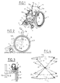
- the wheelchair exemplified in FIG. 1 comprises two carrying wheels 1,2 of large diameter, a seat 3 and a footrest 4 provided, in front of the carrying wheels, with two lateral guide rollers 5.
- each of the carrying wheels 1 or 2 is formed, in the manner of a bearing, of two rings of large diameter 7.8 kept closely in contact, concentrically around one another, by means of rollers 9 interposed between them peripherally and whose axes are perpendicular to the plane of the wheel.
- the annular inner rings 7 of the two carrying wheels 1, 2 thus constitute entirely hollow fixed elements retaining between them the seat support 3 and the independent footrest 4, while the outer ring 8 of each wheel 1 or 2 constitutes the actual rim with a tire 10 disposed around its periphery and a handrail 11 projecting from its outer side.
- the support for the seat 3 is essentially formed of two L-shaped lateral elements 12,13, the vertical branches 12a and 13a of which support the backrest 14 in seat fabric and the horizontal branches 12b and 13b the separate seat 15 also in canvas.
- a double folding arm 16 or 17, forming an armrest is articulated on one side to the vertical branch and, on the other, to the horizontal branch, which are further joined by a hinge 18, self-locking in the deployed position at right angles to the two branches.
- each support element 12, 13 is assembled to the inner edge of the hollowed-out inner ring 7 of a respective load wheel 1 or 2, by two point fastening devices, positioned first on its horizontal branch 12b or 13b and the second on its vertical branch 12a or 13a.
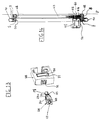
- FIG. 5 shows the first of these identical fixing devices for the two support elements. It consists, on the one hand, of a finger 26 projecting from the inside of the ring 7, perpendicular to its plane and tangentially inside it, and ending in a spherical ball joint 27, and, on the other hand, a part 28, of generally parallelepiped shape, which fits on the horizontal branch 12b or 13b, of rectangular section, of the support element 12 or 13 by a claw 29 of complementary shape, fitted internally with a pawl elastic 30 for blocking the workpiece 28. On the face, opposite the claw 29, of the workpiece 28, there opens an internal housing 31 of the latter into which the ball joint finger is inserted axially.
- the second fixing device visible in FIG. 6 has the same overall structure as the first, except that the parallelepiped part 35 here has the shape of a clamp defined by a fixed part 36 carrying the claw 37 and a movable jaw 38 articulated around a longitudinal axis 39 and urged by a spring or by the own elasticity of the material.
- This clamp is open towards the rear at 55 and the ball joint finger 40 engages there laterally so as to be blocked by the jaw inside the part 35.
- the footrest 4, without connection to the seat 3, is constituted by a closed arch which carries, at each end of its rear branch 4a, a bolt 41 substantially perpendicular to this last, shown in Figure 7,
- This bolt 41 which has a notch 42, is inserted in a keeper 43 secured to the inner ring 7 of the corresponding carrier wheel, in a position slightly recessed inwardly according to its radius by relative to the internal periphery of the latter, the keeper 43 being further provided with an elastic pawl 44 which engages in the notch 42 of the bolt to block it.
- the largest external dimensions in length and in width of the footrest arch 4 are at most equal to the internal diameter of each of the hollowed out inner rings 7 and that the space which it delimits is of a length greater than that of each of the branches 12a, 12b, 13a, 13b of the seat support elements 3.
- the inner annular surface of the hollowed-out inner rings 7 furthermore has a slight conicity open towards the interior of the chair, as shown in 7a in FIG. 3, and, in the exemplified embodiment, the outside length of the hoop 4 is equal to the inside mean diameter of each ring 7.
- each stand 45 consists of a short upper part 46 articulated on the inside of the arch 4 around an axis A parallel to that of the caster 5, and a longer tab 47 pivoting under the part 46 around a second axis B perpendicular to the first A.
- the stands 45 are pivoted successively upwards and laterally around their axes A and B with the rollers 5 to fold the latter flat on the hoop 4 and inside its outline, as shown in dashed lines in FIG. 8.
- the support for the seat 3 is then completely folded around the joints 21 of its braces 19, 20, as shown in dashed lines in FIG. 4, and those 18 of its lateral support elements 12,13, and the fabric quarters 14,15 are rolled around the support of the seat thus folded to form a packet 51.
- After having placed a wheel horizontally, resting on its handrail then installs inside its recess the hoop 4 with its rollers 5 folded.
- the package thus formed, and made rigid by the connections provided by friction between the two wheels, can then be capped around the supporting wheels 1,2 by a circular toric cover 52 with a U-section, provided with handles 53, such as that shown. in Figure 11.
- the package can thus be easily transported in the form of space-saving hand luggage.
- the O-ring cover 52 can of course be replaced by a circular cover which is entirely closed in the center.
- the carrying wheels 1 and 2 can advantageously, according to FIG. 3, receive an external flange 56 situated inside the handrail and occupying its entire surface, being fixed therein in a removable manner or not, such that the volume thus obtained between the two flanges 56 of the two superposed wheels 1 and 2 delimits a receptacle capable of containing all the elements described above.
- the two wheels 1,2 with their flange 56 thus form a rigid and completely closed transport envelope, which can itself be equipped with the cover 52.
- the assembly of the wheelchair will be just as easy as its disassembly, by snap-fastening.
- the wheelchair according to the invention has, once reassembled, a perfect rigidity which is conferred on it by the central frame, namely the seat support 3 and the footrest arch 4, assembled between the inner rings 7, at three mutually distant points along each of them.
- the removable wheelchair according to the invention can also be made self-propelled thanks to a certain number of simple arrangements which do not eliminate any of its aforementioned advantages.
- FIG. 12 illustrates a preferred embodiment of such a self-propelled wheelchair, the large carrying wheels 1, 2 of which are first of all each equipped with a small direct current electric motor 57, of known type.
- this motor 57 is fixed, by its outer carcass 58, on the inner annular surface 59 of the inner ring 7 of this wheel.
- the motor 57, the attachment of which to the inner ring 7, will preferably be reinforced by side props, not shown, is positioned in such a way that its shaft 60 is parallel to the axis of the wheel 1 and is directed towards the outside. of the latter.
- Figure 14 also shows that the outer ring 8 of the wheel 1 is provided, over its entire circumference, with a radial flange 61 which folds in front of the inner ring 7, with a slight spacing from it.
- the folded, annular and continuous branch 62, of this rim 61 carries, on its outer surface, a crown with internal toothing 63, centered on the axis of the wheel 1, with which meshes a pinion 64 mounted free in rotation on the face front of the carcass 58 of the motor 57, this pinion 64 meshing itself with a second pinion 65 wedged on the shaft 60 of the motor.
- Miniature storage batteries 66 are fixed on either side of the engine 57, on its carcass 58, to ensure the electrical supply thereof through a four-position switch , housed in the arm 16 of the seat 3 of the chair, closest to the wheel 1 considered, where it can be actuated by means of a control handle 67 (see FIG. 14).
- each finger as shown in FIG. 13 for that 26 of the first fixing device , has a core 68, conductive of electricity, which carries at its end the ball joint 27 and is enveloped by an insulating sleeve 69, inside the body 70, forming a mass, of the finger 26.
- the pawl 32 is electrically isolated at 71 from the external mass of the part 28.
- the finger 26 of the first fixing device has a polygonal section, here rectangular, and the housing 31, in which it is inserted, has an exactly complementary section, thus a perfect rigidity is guaranteed.
- the end part 26a of the finger 26 is also slightly tapered to facilitate centering of the latter during its introduction into the housing 31 of the part 28.
- any suitable means other than the set of pinions 64, 65 can be used to make the kinematic connection between the shaft 60 of the motor 57 and the ring gear 63 of the outer ring 8 of the wheel 1, by virtue of at which the latter is rotated around the fixed inner ring 7, in one direction or the other, and at a selectable speed, from the control lever 67.
- This set of pinions can be replaced by a friction roller or a set of such rollers in contact with the inner annular surface 62, in this case smooth and provided with a coating with a high coefficient of friction, of the outer ring 8 of the wheel 1.
- the second load wheel 2 is arranged in the same way as the first, with an engine-battery assembly, electrical connections and a control, as described above.
- FIG 15 shows that, thanks to these provisions, the two wheels 1 and 2 of the self-propelled wheelchair of Figure 12 can be superimposed on each other, without leaving any parts protruding, in the same way as those of the wheelchair described above.
- the motor 57 and its batteries 66 are confined inside a housing delimited by the inner ring 7 of the wheel 1 or 2 considered and a cord of this ring, symbolized by the dashed line 72 in FIG. 12.
- This cord 72 which can moreover be embodied by a narrow plate further stiffening the fixing of the motor, is in a position such that after the two disassembled wheels 1,2 are superimposed, as in FIG. 15, the motors 57, with their batteries 66, do not encroach on the space 73 reserved, inside the two wheels, for the installation of the arch 4 at the center of which is then placed the package 51 formed by the seat 3 folded and wound on itself, as shown in Figure 10 for the first non-self-propelled wheelchair.
- the self-propelled wheelchair of FIG. 12 can, after disassembly, be put in the form of a package of minimum volume easily transportable in a bag in the form of a cover. toric such as that of figure 11.
Landscapes
- Life Sciences & Earth Sciences (AREA)
- Animal Behavior & Ethology (AREA)
- General Health & Medical Sciences (AREA)
- Public Health (AREA)
- Veterinary Medicine (AREA)
- Health & Medical Sciences (AREA)
- Handcart (AREA)
- Bag Frames (AREA)
- Packages (AREA)
- Motorcycle And Bicycle Frame (AREA)
- Laminated Bodies (AREA)
- Professional, Industrial, Or Sporting Protective Garments (AREA)
- Purses, Travelling Bags, Baskets, Or Suitcases (AREA)
- Auxiliary Devices For And Details Of Packaging Control (AREA)
- Gloves (AREA)
- Automatic Cycles, And Cycles In General (AREA)
- Tires In General (AREA)
- Chairs Characterized By Structure (AREA)
Applications Claiming Priority (2)
| Application Number | Priority Date | Filing Date | Title |
|---|---|---|---|
| FR8915647A FR2654927B1 (fr) | 1989-11-28 | 1989-11-28 | Fauteuil roulant demontable. |
| FR8915647 | 1989-11-28 |
Publications (2)
| Publication Number | Publication Date |
|---|---|
| EP0430794A1 EP0430794A1 (fr) | 1991-06-05 |
| EP0430794B1 true EP0430794B1 (fr) | 1994-08-24 |
Family
ID=9387870
Family Applications (1)
| Application Number | Title | Priority Date | Filing Date |
|---|---|---|---|
| EP90403358A Expired - Lifetime EP0430794B1 (fr) | 1989-11-28 | 1990-11-27 | Fauteuil roulant démontable et sac pour le transport d'un tel fauteuil après son démontage |
Country Status (13)
| Country | Link |
|---|---|
| US (1) | US5261684A (ru) |
| EP (1) | EP0430794B1 (ru) |
| JP (1) | JP2960161B2 (ru) |
| AT (1) | ATE110253T1 (ru) |
| AU (1) | AU651075B2 (ru) |
| CA (1) | CA2045476C (ru) |
| DE (1) | DE69011822T2 (ru) |
| DK (1) | DK0430794T3 (ru) |
| ES (1) | ES2063943T3 (ru) |
| FR (1) | FR2654927B1 (ru) |
| IL (1) | IL96481A (ru) |
| RU (1) | RU2066165C1 (ru) |
| WO (1) | WO1991007935A1 (ru) |
Cited By (1)
| Publication number | Priority date | Publication date | Assignee | Title |
|---|---|---|---|---|
| DE19811686A1 (de) * | 1998-03-18 | 1999-09-23 | Leibe Klaus | Nabenfreies Laufrad für Fahrzeuge zur Personenbeförderung, insbesondere für Rollstühle |
Families Citing this family (27)
| Publication number | Priority date | Publication date | Assignee | Title |
|---|---|---|---|---|
| WO1994026227A1 (de) * | 1993-05-12 | 1994-11-24 | Elke Stimpfig | Rollstuhl, insbesondere für körperbehinderte personen |
| US5427398A (en) * | 1993-10-29 | 1995-06-27 | Weybrecht; Steven L. | All-terrain wheelchairs and apparatus therefor |
| DE19525719B4 (de) * | 1994-07-14 | 2004-08-26 | Everest & Jennings International Ltd. | Rollstuhl und Rollstuhlrahmen mit Aufhängung |
| US5669619A (en) * | 1995-08-22 | 1997-09-23 | Kim; Il Yoo | Portable wheelchair |
| US5681049A (en) * | 1995-08-22 | 1997-10-28 | Kim; Il Yoo | Portable wheelchair |
| WO1998023239A1 (fr) * | 1996-11-23 | 1998-06-04 | Ichiro Fujioka | Fauteuil roulant assiste par un moteur electrique et mecanisme d'actionnement de ce dernier |
| CA2279216A1 (en) * | 1997-02-06 | 1998-08-13 | Borringia Industrie Ag | A set of releasably interconnectable members for building up a chair for disabled persons |
| US6241321B1 (en) * | 1999-05-13 | 2001-06-05 | Brian Gagnon | All terrain wheel for a wheelchair |
| DE20120619U1 (de) | 2001-12-20 | 2002-03-21 | Alber Antriebstechnik GmbH, 72458 Albstadt | Antriebs- und Bremshilfsvorrichtung für Rollstühle |
| JP4347607B2 (ja) * | 2003-05-20 | 2009-10-21 | 川村義肢株式会社 | 車椅子、及び車椅子用車輪、並びに車椅子用車輪の製造方法 |
| EP1522291A3 (en) * | 2003-10-08 | 2006-01-04 | Pride Mobility Products, Corporation | Modular wheelchair assembly |
| US7425010B2 (en) * | 2004-10-18 | 2008-09-16 | Pride Mobility Products Corporation | Mount for a wheelchair footrest |
| WO2007079346A2 (en) * | 2005-12-30 | 2007-07-12 | Olsen Christopher J | Articulated wheel assemblies and vehicles therewith |
| US20090312118A1 (en) * | 2007-02-23 | 2009-12-17 | Uday Deshmukh | High performance nano-structured metalwood golf club heads and iron heads and components thereof |
| IL200080A0 (en) * | 2009-07-27 | 2010-04-15 | Ruth Reuveni | Singular wheelchair |
| JP5582350B2 (ja) * | 2010-12-21 | 2014-09-03 | ハンマーキャスター株式会社 | 車輪 |
| AU2015232943B2 (en) * | 2014-03-20 | 2020-08-27 | Resqdevices Pty Ltd | A transport and components therefor |
| GB2552650B (en) * | 2016-07-26 | 2019-02-06 | Rallings Alan | Centreless wheel with drive |
| US11370497B2 (en) | 2016-10-18 | 2022-06-28 | Piaggio Fast Forward, Inc. | Vehicle having non-axial drive and stabilization system |
| IT201700007710A1 (it) * | 2017-01-25 | 2018-07-25 | Piaggio Fast Forward Inc | Three-Wheeled Vehicle having Non-Axial Drive |
| US10730586B2 (en) * | 2017-09-15 | 2020-08-04 | Orbis Wheels, Inc. | Energy recovery system and method of power transmission |
| IT201700114497A1 (it) | 2017-10-11 | 2019-04-11 | Piaggio Fast Forward Inc | Veicolo a due ruote con sistema di stabilizzazione lineare |
| CA3098000C (en) | 2018-05-01 | 2021-12-07 | Piaggio Fast Forward, Inc. | Method for determining self-driving vehicle behavior models, a self-driving vehicle, and a method of navigating a self-driving vehicle |
| CN108714076B (zh) * | 2018-08-01 | 2023-10-31 | 江西博致电子技术有限公司 | 一种电动观光轮椅 |
| KR20210078498A (ko) | 2018-10-22 | 2021-06-28 | 피아지오 패스트 포워드 인코포레이티드 | 변위 장치 조립체와 이를 구비하는 모바일 캐리어 |
| EP3656364A1 (en) * | 2018-11-22 | 2020-05-27 | Invacare International GmbH | Motorized wheelchair chassis and motorized wheelchair comprising the same |
| CN112716708B (zh) * | 2021-02-24 | 2023-04-25 | 海南大学 | 一种多功能助起轮椅 |
Family Cites Families (11)
| Publication number | Priority date | Publication date | Assignee | Title |
|---|---|---|---|---|
| US970291A (en) * | 1909-01-22 | 1910-09-13 | Edward James Baisden | Rim-bearing wheel. |
| US3381973A (en) * | 1966-08-25 | 1968-05-07 | Lottie M. Carr | Combination invalid's chair and cot |
| SE420160B (sv) * | 1980-06-13 | 1981-09-21 | Per Gotthold Bergman | Underrede for sittenhet vid rullstol |
| US4462605A (en) * | 1981-05-29 | 1984-07-31 | Georgia Tech Research Institute | Wheelchair having anti-rollback mechanism |
| US4593929A (en) * | 1983-01-12 | 1986-06-10 | Williams Ronald H | Wheelchair |
| US4770432A (en) * | 1986-08-15 | 1988-09-13 | Iatrics | Wheelchair |
| GB2206088A (en) * | 1987-06-09 | 1988-12-29 | Edward Thipthorpe Ruse | Step-negotiating wheelchair; wheelchair seats |
| DD265324A1 (de) * | 1987-10-02 | 1989-03-01 | Medizin Labortechnik Veb K | Rollstuhl fuer koerperbehinderte |
| SU1503807A1 (ru) * | 1987-12-30 | 1989-08-30 | Н. Н. Вир сов | Инвалидна кол ска |
| US4887826A (en) * | 1988-06-10 | 1989-12-19 | Kantner Richard D | Lightweight foldable wheelchair |
| FR2633877B1 (fr) * | 1988-07-11 | 1994-03-25 | Mottas Dominique | Roue pour vehicule motorise ou tracte et vehicule equipe d'une telle roue |
-
1989
- 1989-11-28 FR FR8915647A patent/FR2654927B1/fr not_active Expired - Fee Related
-
1990
- 1990-11-27 DK DK90403358.6T patent/DK0430794T3/da active
- 1990-11-27 US US07/730,824 patent/US5261684A/en not_active Expired - Fee Related
- 1990-11-27 RU SU905001293A patent/RU2066165C1/ru not_active IP Right Cessation
- 1990-11-27 EP EP90403358A patent/EP0430794B1/fr not_active Expired - Lifetime
- 1990-11-27 WO PCT/FR1990/000856 patent/WO1991007935A1/fr active Application Filing
- 1990-11-27 IL IL9648190A patent/IL96481A/en unknown
- 1990-11-27 ES ES90403358T patent/ES2063943T3/es not_active Expired - Lifetime
- 1990-11-27 AT AT90403358T patent/ATE110253T1/de not_active IP Right Cessation
- 1990-11-27 JP JP3500972A patent/JP2960161B2/ja not_active Expired - Lifetime
- 1990-11-27 AU AU69048/91A patent/AU651075B2/en not_active Ceased
- 1990-11-27 CA CA002045476A patent/CA2045476C/en not_active Expired - Fee Related
- 1990-11-27 DE DE69011822T patent/DE69011822T2/de not_active Expired - Fee Related
Cited By (1)
| Publication number | Priority date | Publication date | Assignee | Title |
|---|---|---|---|---|
| DE19811686A1 (de) * | 1998-03-18 | 1999-09-23 | Leibe Klaus | Nabenfreies Laufrad für Fahrzeuge zur Personenbeförderung, insbesondere für Rollstühle |
Also Published As
| Publication number | Publication date |
|---|---|
| ES2063943T3 (es) | 1995-01-16 |
| CA2045476A1 (en) | 1991-05-29 |
| RU2066165C1 (ru) | 1996-09-10 |
| AU6904891A (en) | 1991-06-26 |
| IL96481A0 (en) | 1991-08-16 |
| JP2960161B2 (ja) | 1999-10-06 |
| JPH04503180A (ja) | 1992-06-11 |
| IL96481A (en) | 1994-04-12 |
| US5261684A (en) | 1993-11-16 |
| WO1991007935A1 (fr) | 1991-06-13 |
| EP0430794A1 (fr) | 1991-06-05 |
| DK0430794T3 (da) | 1995-03-20 |
| FR2654927B1 (fr) | 1994-02-11 |
| AU651075B2 (en) | 1994-07-14 |
| CA2045476C (en) | 2001-07-03 |
| ATE110253T1 (de) | 1994-09-15 |
| DE69011822D1 (de) | 1994-09-29 |
| DE69011822T2 (de) | 1995-04-20 |
| FR2654927A1 (fr) | 1991-05-31 |
Similar Documents
| Publication | Publication Date | Title |
|---|---|---|
| EP0430794B1 (fr) | Fauteuil roulant démontable et sac pour le transport d'un tel fauteuil après son démontage | |
| EP0939019B1 (fr) | Véhicule de déplacement pour enfant en bas âge | |
| EP2531393B1 (fr) | Vehicule a deux roues depliable | |
| EP0059141B1 (fr) | Fauteuil roulant permettant le redressement de son utilisateur | |
| EP2244924B1 (fr) | Châssis de poussette, notamment pour transporter un enfant | |
| CA1283670C (fr) | Chariot pliable, destine en particulier au transport d'un sac recevant des clubs de golf | |
| FR2642721A1 (fr) | Vehicule personnel convertible comportant un chassis en plusieurs elements | |
| EP3680146B1 (fr) | Accessoire pour poussette, ainsi qu'ensemble formant poussette double | |
| FR2898489A1 (fr) | Fauteuil roulant adapte aux escaliers | |
| FR3100213A1 (fr) | Vehicule electrique | |
| FR2846570A1 (fr) | Vehicule jouet | |
| FR2573304A1 (fr) | Fauteuil pliable en particulier fauteuil roulant pliable pour handicapes | |
| FR2841462A1 (fr) | Module de transformation pour fauteuil roulant | |
| FR2567472A1 (fr) | Voiture repliable pour enfants | |
| EP1115592B1 (fr) | Siege inclinable pour enfants a cotes lateraux pivotants | |
| EP2181683B1 (fr) | Fauteuil roulant | |
| EP3353038B1 (fr) | Poignée pliante de poussette pour enfant | |
| FR2918654A1 (fr) | Structure roulante repliable de support d'un rouleau rotatif sur lequel peut etre enroulee une bache. | |
| EP0425342A1 (fr) | Chariot de golf motorisé | |
| FR2882007A1 (fr) | Agencement de sieges dans un vehicule automobile et vehicule automobile equipe d'un tel agencement | |
| EP2671555A1 (fr) | Kit de motorisation pour chaises roulantes | |
| WO2010125305A1 (fr) | Poussette pliable ainsi que procédé d'ouverture et de pliage de cette poussette | |
| FR2855112A1 (fr) | Siege pliable et vehicule comportant un seige pliable encastrable sous un autre siege. | |
| FR2987814A1 (fr) | Vehicule a deux roues dont la longueur est reductible par repliage du cadre | |
| WO2022254099A1 (fr) | Bicyclette pliable |
Legal Events
| Date | Code | Title | Description |
|---|---|---|---|
| PUAI | Public reference made under article 153(3) epc to a published international application that has entered the european phase |
Free format text: ORIGINAL CODE: 0009012 |
|
| AK | Designated contracting states |
Kind code of ref document: A1 Designated state(s): AT BE CH DE DK ES FR GB GR IT LI LU NL SE |
|
| 17P | Request for examination filed |
Effective date: 19911025 |
|
| 17Q | First examination report despatched |
Effective date: 19930316 |
|
| GRAA | (expected) grant |
Free format text: ORIGINAL CODE: 0009210 |
|
| AK | Designated contracting states |
Kind code of ref document: B1 Designated state(s): AT BE CH DE DK ES FR GB GR IT LI LU NL SE |
|
| REF | Corresponds to: |
Ref document number: 110253 Country of ref document: AT Date of ref document: 19940915 Kind code of ref document: T |
|
| REF | Corresponds to: |
Ref document number: 69011822 Country of ref document: DE Date of ref document: 19940929 |
|
| ITF | It: translation for a ep patent filed | ||
| PG25 | Lapsed in a contracting state [announced via postgrant information from national office to epo] |
Ref country code: LU Free format text: LAPSE BECAUSE OF NON-PAYMENT OF DUE FEES Effective date: 19941130 |
|
| GBT | Gb: translation of ep patent filed (gb section 77(6)(a)/1977) |
Effective date: 19941129 |
|
| REG | Reference to a national code |
Ref country code: ES Ref legal event code: FG2A Ref document number: 2063943 Country of ref document: ES Kind code of ref document: T3 |
|
| EAL | Se: european patent in force in sweden |
Ref document number: 90403358.6 |
|
| REG | Reference to a national code |
Ref country code: GR Ref legal event code: FG4A Free format text: 3014049 |
|
| REG | Reference to a national code |
Ref country code: DK Ref legal event code: T3 |
|
| PLBE | No opposition filed within time limit |
Free format text: ORIGINAL CODE: 0009261 |
|
| STAA | Information on the status of an ep patent application or granted ep patent |
Free format text: STATUS: NO OPPOSITION FILED WITHIN TIME LIMIT |
|
| 26N | No opposition filed | ||
| REG | Reference to a national code |
Ref country code: CH Ref legal event code: NV Representative=s name: ARDIN & CIE S.A. |
|
| REG | Reference to a national code |
Ref country code: GB Ref legal event code: IF02 |
|
| REG | Reference to a national code |
Ref country code: FR Ref legal event code: ST |
|
| REG | Reference to a national code |
Ref country code: FR Ref legal event code: FC Ref country code: FR Ref legal event code: RN |
|
| PGFP | Annual fee paid to national office [announced via postgrant information from national office to epo] |
Ref country code: ES Payment date: 20041124 Year of fee payment: 15 Ref country code: GB Payment date: 20041124 Year of fee payment: 15 |
|
| PGFP | Annual fee paid to national office [announced via postgrant information from national office to epo] |
Ref country code: SE Payment date: 20041125 Year of fee payment: 15 |
|
| PGFP | Annual fee paid to national office [announced via postgrant information from national office to epo] |
Ref country code: FR Payment date: 20041127 Year of fee payment: 15 |
|
| PGFP | Annual fee paid to national office [announced via postgrant information from national office to epo] |
Ref country code: GR Payment date: 20041129 Year of fee payment: 15 Ref country code: DE Payment date: 20041129 Year of fee payment: 15 |
|
| PGFP | Annual fee paid to national office [announced via postgrant information from national office to epo] |
Ref country code: NL Payment date: 20041130 Year of fee payment: 15 Ref country code: LU Payment date: 20041130 Year of fee payment: 15 Ref country code: AT Payment date: 20041130 Year of fee payment: 15 Ref country code: DK Payment date: 20041130 Year of fee payment: 15 |
|
| PGFP | Annual fee paid to national office [announced via postgrant information from national office to epo] |
Ref country code: CH Payment date: 20041201 Year of fee payment: 15 |
|
| PGFP | Annual fee paid to national office [announced via postgrant information from national office to epo] |
Ref country code: BE Payment date: 20041209 Year of fee payment: 15 |
|
| PG25 | Lapsed in a contracting state [announced via postgrant information from national office to epo] |
Ref country code: AT Free format text: LAPSE BECAUSE OF NON-PAYMENT OF DUE FEES Effective date: 20051127 Ref country code: GB Free format text: LAPSE BECAUSE OF NON-PAYMENT OF DUE FEES Effective date: 20051127 Ref country code: IT Free format text: LAPSE BECAUSE OF NON-PAYMENT OF DUE FEES;WARNING: LAPSES OF ITALIAN PATENTS WITH EFFECTIVE DATE BEFORE 2007 MAY HAVE OCCURRED AT ANY TIME BEFORE 2007. THE CORRECT EFFECTIVE DATE MAY BE DIFFERENT FROM THE ONE RECORDED. Effective date: 20051127 |
|
| PG25 | Lapsed in a contracting state [announced via postgrant information from national office to epo] |
Ref country code: ES Free format text: LAPSE BECAUSE OF NON-PAYMENT OF DUE FEES Effective date: 20051128 Ref country code: SE Free format text: LAPSE BECAUSE OF NON-PAYMENT OF DUE FEES Effective date: 20051128 |
|
| PG25 | Lapsed in a contracting state [announced via postgrant information from national office to epo] |
Ref country code: LI Free format text: LAPSE BECAUSE OF NON-PAYMENT OF DUE FEES Effective date: 20051130 Ref country code: CH Free format text: LAPSE BECAUSE OF NON-PAYMENT OF DUE FEES Effective date: 20051130 Ref country code: DK Free format text: LAPSE BECAUSE OF NON-PAYMENT OF DUE FEES Effective date: 20051130 Ref country code: BE Free format text: LAPSE BECAUSE OF NON-PAYMENT OF DUE FEES Effective date: 20051130 |
|
| PG25 | Lapsed in a contracting state [announced via postgrant information from national office to epo] |
Ref country code: NL Free format text: LAPSE BECAUSE OF NON-PAYMENT OF DUE FEES Effective date: 20060601 Ref country code: DE Free format text: LAPSE BECAUSE OF NON-PAYMENT OF DUE FEES Effective date: 20060601 |
|
| REG | Reference to a national code |
Ref country code: DK Ref legal event code: EBP |
|
| REG | Reference to a national code |
Ref country code: CH Ref legal event code: PL |
|
| EUG | Se: european patent has lapsed | ||
| GBPC | Gb: european patent ceased through non-payment of renewal fee |
Effective date: 20051127 |
|
| PG25 | Lapsed in a contracting state [announced via postgrant information from national office to epo] |
Ref country code: FR Free format text: LAPSE BECAUSE OF NON-PAYMENT OF DUE FEES Effective date: 20060731 |
|
| NLV4 | Nl: lapsed or anulled due to non-payment of the annual fee |
Effective date: 20060601 |
|
| REG | Reference to a national code |
Ref country code: FR Ref legal event code: ST Effective date: 20060731 |
|
| REG | Reference to a national code |
Ref country code: ES Ref legal event code: FD2A Effective date: 20051128 |
|
| BERE | Be: lapsed |
Owner name: *SOTO PIERRE JOSE Effective date: 20051130 |
|
| PG25 | Lapsed in a contracting state [announced via postgrant information from national office to epo] |
Ref country code: GR Free format text: LAPSE BECAUSE OF NON-PAYMENT OF DUE FEES Effective date: 19940824 |