EP0430794B1 - Collapsible wheelchair and bag for transporting such a chair when collapsed - Google Patents
Collapsible wheelchair and bag for transporting such a chair when collapsed Download PDFInfo
- Publication number
- EP0430794B1 EP0430794B1 EP90403358A EP90403358A EP0430794B1 EP 0430794 B1 EP0430794 B1 EP 0430794B1 EP 90403358 A EP90403358 A EP 90403358A EP 90403358 A EP90403358 A EP 90403358A EP 0430794 B1 EP0430794 B1 EP 0430794B1
- Authority
- EP
- European Patent Office
- Prior art keywords
- wheelchair according
- wheel
- inner ring
- wheels
- ring
- Prior art date
- Legal status (The legal status is an assumption and is not a legal conclusion. Google has not performed a legal analysis and makes no representation as to the accuracy of the status listed.)
- Expired - Lifetime
Links
Images


Classifications
-
- A—HUMAN NECESSITIES
- A61—MEDICAL OR VETERINARY SCIENCE; HYGIENE
- A61G—TRANSPORT, PERSONAL CONVEYANCES, OR ACCOMMODATION SPECIALLY ADAPTED FOR PATIENTS OR DISABLED PERSONS; OPERATING TABLES OR CHAIRS; CHAIRS FOR DENTISTRY; FUNERAL DEVICES
- A61G5/00—Chairs or personal conveyances specially adapted for patients or disabled persons, e.g. wheelchairs
- A61G5/04—Chairs or personal conveyances specially adapted for patients or disabled persons, e.g. wheelchairs motor-driven
- A61G5/041—Chairs or personal conveyances specially adapted for patients or disabled persons, e.g. wheelchairs motor-driven having a specific drive-type
- A61G5/045—Rear wheel drive
-
- A—HUMAN NECESSITIES
- A61—MEDICAL OR VETERINARY SCIENCE; HYGIENE
- A61G—TRANSPORT, PERSONAL CONVEYANCES, OR ACCOMMODATION SPECIALLY ADAPTED FOR PATIENTS OR DISABLED PERSONS; OPERATING TABLES OR CHAIRS; CHAIRS FOR DENTISTRY; FUNERAL DEVICES
- A61G5/00—Chairs or personal conveyances specially adapted for patients or disabled persons, e.g. wheelchairs
- A61G5/02—Chairs or personal conveyances specially adapted for patients or disabled persons, e.g. wheelchairs propelled by the patient or disabled person
- A61G5/028—Special adaptations or provisions on hand rim, e.g. for facilitating gripping
-
- A—HUMAN NECESSITIES
- A61—MEDICAL OR VETERINARY SCIENCE; HYGIENE
- A61G—TRANSPORT, PERSONAL CONVEYANCES, OR ACCOMMODATION SPECIALLY ADAPTED FOR PATIENTS OR DISABLED PERSONS; OPERATING TABLES OR CHAIRS; CHAIRS FOR DENTISTRY; FUNERAL DEVICES
- A61G5/00—Chairs or personal conveyances specially adapted for patients or disabled persons, e.g. wheelchairs
- A61G5/08—Chairs or personal conveyances specially adapted for patients or disabled persons, e.g. wheelchairs foldable
- A61G5/0808—Chairs or personal conveyances specially adapted for patients or disabled persons, e.g. wheelchairs foldable characterised by a particular folding direction
- A61G5/0816—Chairs or personal conveyances specially adapted for patients or disabled persons, e.g. wheelchairs foldable characterised by a particular folding direction folding side to side, e.g. reducing or expanding the overall width of the wheelchair
- A61G5/0825—Chairs or personal conveyances specially adapted for patients or disabled persons, e.g. wheelchairs foldable characterised by a particular folding direction folding side to side, e.g. reducing or expanding the overall width of the wheelchair comprising a scissor-type frame, e.g. having pivoting cross bars for enabling folding
-
- A—HUMAN NECESSITIES
- A61—MEDICAL OR VETERINARY SCIENCE; HYGIENE
- A61G—TRANSPORT, PERSONAL CONVEYANCES, OR ACCOMMODATION SPECIALLY ADAPTED FOR PATIENTS OR DISABLED PERSONS; OPERATING TABLES OR CHAIRS; CHAIRS FOR DENTISTRY; FUNERAL DEVICES
- A61G5/00—Chairs or personal conveyances specially adapted for patients or disabled persons, e.g. wheelchairs
- A61G5/10—Parts, details or accessories
- A61G5/1054—Large wheels, e.g. higher than the seat portion
-
- A—HUMAN NECESSITIES
- A61—MEDICAL OR VETERINARY SCIENCE; HYGIENE
- A61G—TRANSPORT, PERSONAL CONVEYANCES, OR ACCOMMODATION SPECIALLY ADAPTED FOR PATIENTS OR DISABLED PERSONS; OPERATING TABLES OR CHAIRS; CHAIRS FOR DENTISTRY; FUNERAL DEVICES
- A61G5/00—Chairs or personal conveyances specially adapted for patients or disabled persons, e.g. wheelchairs
- A61G5/10—Parts, details or accessories
- A61G5/12—Rests specially adapted therefor, e.g. for the head or the feet
- A61G5/125—Rests specially adapted therefor, e.g. for the head or the feet for arms
-
- A—HUMAN NECESSITIES
- A61—MEDICAL OR VETERINARY SCIENCE; HYGIENE
- A61G—TRANSPORT, PERSONAL CONVEYANCES, OR ACCOMMODATION SPECIALLY ADAPTED FOR PATIENTS OR DISABLED PERSONS; OPERATING TABLES OR CHAIRS; CHAIRS FOR DENTISTRY; FUNERAL DEVICES
- A61G5/00—Chairs or personal conveyances specially adapted for patients or disabled persons, e.g. wheelchairs
- A61G5/10—Parts, details or accessories
- A61G5/12—Rests specially adapted therefor, e.g. for the head or the feet
- A61G5/128—Rests specially adapted therefor, e.g. for the head or the feet for feet
-
- A—HUMAN NECESSITIES
- A61—MEDICAL OR VETERINARY SCIENCE; HYGIENE
- A61G—TRANSPORT, PERSONAL CONVEYANCES, OR ACCOMMODATION SPECIALLY ADAPTED FOR PATIENTS OR DISABLED PERSONS; OPERATING TABLES OR CHAIRS; CHAIRS FOR DENTISTRY; FUNERAL DEVICES
- A61G5/00—Chairs or personal conveyances specially adapted for patients or disabled persons, e.g. wheelchairs
- A61G5/10—Parts, details or accessories
- A61G5/1056—Arrangements for adjusting the seat
- A61G5/1059—Arrangements for adjusting the seat adjusting the height of the seat
Definitions
- the present invention relates to a wheelchair, of the type comprising two large carrying wheels mounted on either side of a central frame, part of which supports a seat and another part constitutes a footrest provided with steered wheels.
- Wheelchairs of this type most often have a folding structure so that they can be stored in tight spaces, and in particular in the boot of a motor vehicle.
- the present invention proposes to remedy this drawback and, to do this, it relates to a wheelchair of the type specified in the introduction, which is characterized in that each of its carrying wheels is formed of a rim which, carrying the pneumatic, directly constitutes the outer ring of a peripheral bearing whose inner ring, of large diameter, devoid of any hub, shaft or radius, carries the frame fixed to it by releasable fixing means.
- the seat of the wheelchair and the part of the frame which supports it form a separate assembly from the footrest, which has a folding structure designed and dimensioned such that once separated from the wheels and folded, said assembly forms a packet whose volume is entirely contained in that delimited by the two superimposed carrying wheels.
- the footrest independent of the rest of the frame, has the shape of a closed arch projecting from the front of the load wheels and held at its rear between them by releasable means of attachment to their inner ring. respective, this hoop advantageously having, in all directions, external dimensions at most equal to those of the space delimited by the two superimposed supporting wheels as well as an internal length and width preferably greater than the corresponding dimensions of the package constituted by the seat and its support disassembled and folded.
- each of the steering wheels of the chair is preferably supported by a pivoting stand mounted on a respective lateral branch of the roll bar by an articulation with an axis perpendicular to the pivot axis of the stand, and comprising a retractable member d immobilization in the deployed position.
- the means for fixing, to the inner rings of the carrying wheels, the footrest arch are formed at each end of the rear branch of this one, by a bolt provided with a notch, which slides in an internal elastic ratchet keeper, integral with the inner ring of the corresponding load wheel, and that on each side of the seat support part of the frame , the means for fixing the latter to the respective inner ring comprise two groups, mutually distant along the periphery of the latter, of two elements assembly snap into each other, one of these elements being integral with the inner side of the inner ring and the other on the opposite side of said seat support portion of the frame.
- one of the assembly elements is a protruding finger ending in a ball joint and the other is a receiving part provided with a housing for inserting this finger and an elastic pawl, the receiving part of at least one of the groups having the shape of a clamp in which the corresponding projecting finger engages laterally.
- the protruding finger prefferably has, over at least part of its length, a polygonal cross section and for the housing provided in the receiving part to have a cross section complementary to that of the finger.
- the position of at least one of the assembly elements of each group is adjustable along the inner side of the corresponding inner ring and or respectively on the opposite side of the seat support part of the frame to allow a easy adjustment of the seat height or its lateral or rear tilt.
- the removable wheelchair according to the invention can also be made self-propelled without losing the aforementioned advantages, namely essentially the possibilities of rapid assembly and disassembly and the storage of its various constituent elements in a minimum volume, facilitating its transport.
- each of the two carrying wheels of the chair is advantageously provided with a motor carried by one of its rings and causing the second ring to rotate by means of a transmission mechanism cooperating with the latter, the motor , and possibly its source, the energy supply, being retained inside the central recess of the wheel considered without encroaching on a space having, in the plane of said wheel, dimensions smaller than the transverse dimensions and longitudinal of the arch.
- the motor and optionally its power supply source, is carried by the inner annular surface of the ring inner of the wheel considered, and the outer ring has a flange of which an annular part, folded in front of the inner ring, cooperates with said motor transmission mechanism.
- said transmission mechanism is constituted by a pinion or a set of pinions, meshing with a crown with internal toothing carried by said annular part folded back from the outer ring. It may alternatively consist of a friction roller or a set of friction rollers cooperating with a coating with a high coefficient of friction of said annular part.
- the motor in a direction parallel to the axis of the wheel, the motor, with its transmission mechanism and possibly its energy supply source, has a dimension less than twice the thickness of the wheel and does not go not beyond a lateral plane of congestion of the latter.
- the two assembly elements of at least one of the groups are advantageously provided respectively with electrically conductive interior parts, in mutual contact, each isolated from the external body forming the mass of the assembly element considered, this to, when reassembling the chair, be able to play the role of automatic electrical connectors which can be used to, in the case of the use of an electric motor, close the electric control circuit of the latter.
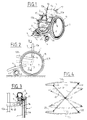
- the wheelchair exemplified in FIG. 1 comprises two carrying wheels 1,2 of large diameter, a seat 3 and a footrest 4 provided, in front of the carrying wheels, with two lateral guide rollers 5.
- each of the carrying wheels 1 or 2 is formed, in the manner of a bearing, of two rings of large diameter 7.8 kept closely in contact, concentrically around one another, by means of rollers 9 interposed between them peripherally and whose axes are perpendicular to the plane of the wheel.
- the annular inner rings 7 of the two carrying wheels 1, 2 thus constitute entirely hollow fixed elements retaining between them the seat support 3 and the independent footrest 4, while the outer ring 8 of each wheel 1 or 2 constitutes the actual rim with a tire 10 disposed around its periphery and a handrail 11 projecting from its outer side.
- the support for the seat 3 is essentially formed of two L-shaped lateral elements 12,13, the vertical branches 12a and 13a of which support the backrest 14 in seat fabric and the horizontal branches 12b and 13b the separate seat 15 also in canvas.
- a double folding arm 16 or 17, forming an armrest is articulated on one side to the vertical branch and, on the other, to the horizontal branch, which are further joined by a hinge 18, self-locking in the deployed position at right angles to the two branches.
- each support element 12, 13 is assembled to the inner edge of the hollowed-out inner ring 7 of a respective load wheel 1 or 2, by two point fastening devices, positioned first on its horizontal branch 12b or 13b and the second on its vertical branch 12a or 13a.
- FIG. 5 shows the first of these identical fixing devices for the two support elements. It consists, on the one hand, of a finger 26 projecting from the inside of the ring 7, perpendicular to its plane and tangentially inside it, and ending in a spherical ball joint 27, and, on the other hand, a part 28, of generally parallelepiped shape, which fits on the horizontal branch 12b or 13b, of rectangular section, of the support element 12 or 13 by a claw 29 of complementary shape, fitted internally with a pawl elastic 30 for blocking the workpiece 28. On the face, opposite the claw 29, of the workpiece 28, there opens an internal housing 31 of the latter into which the ball joint finger is inserted axially.
- the second fixing device visible in FIG. 6 has the same overall structure as the first, except that the parallelepiped part 35 here has the shape of a clamp defined by a fixed part 36 carrying the claw 37 and a movable jaw 38 articulated around a longitudinal axis 39 and urged by a spring or by the own elasticity of the material.
- This clamp is open towards the rear at 55 and the ball joint finger 40 engages there laterally so as to be blocked by the jaw inside the part 35.
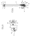
- the footrest 4, without connection to the seat 3, is constituted by a closed arch which carries, at each end of its rear branch 4a, a bolt 41 substantially perpendicular to this last, shown in Figure 7,
- This bolt 41 which has a notch 42, is inserted in a keeper 43 secured to the inner ring 7 of the corresponding carrier wheel, in a position slightly recessed inwardly according to its radius by relative to the internal periphery of the latter, the keeper 43 being further provided with an elastic pawl 44 which engages in the notch 42 of the bolt to block it.
- the largest external dimensions in length and in width of the footrest arch 4 are at most equal to the internal diameter of each of the hollowed out inner rings 7 and that the space which it delimits is of a length greater than that of each of the branches 12a, 12b, 13a, 13b of the seat support elements 3.
- the inner annular surface of the hollowed-out inner rings 7 furthermore has a slight conicity open towards the interior of the chair, as shown in 7a in FIG. 3, and, in the exemplified embodiment, the outside length of the hoop 4 is equal to the inside mean diameter of each ring 7.
- each stand 45 consists of a short upper part 46 articulated on the inside of the arch 4 around an axis A parallel to that of the caster 5, and a longer tab 47 pivoting under the part 46 around a second axis B perpendicular to the first A.
- the stands 45 are pivoted successively upwards and laterally around their axes A and B with the rollers 5 to fold the latter flat on the hoop 4 and inside its outline, as shown in dashed lines in FIG. 8.
- the support for the seat 3 is then completely folded around the joints 21 of its braces 19, 20, as shown in dashed lines in FIG. 4, and those 18 of its lateral support elements 12,13, and the fabric quarters 14,15 are rolled around the support of the seat thus folded to form a packet 51.
- After having placed a wheel horizontally, resting on its handrail then installs inside its recess the hoop 4 with its rollers 5 folded.
- the package thus formed, and made rigid by the connections provided by friction between the two wheels, can then be capped around the supporting wheels 1,2 by a circular toric cover 52 with a U-section, provided with handles 53, such as that shown. in Figure 11.
- the package can thus be easily transported in the form of space-saving hand luggage.
- the O-ring cover 52 can of course be replaced by a circular cover which is entirely closed in the center.
- the carrying wheels 1 and 2 can advantageously, according to FIG. 3, receive an external flange 56 situated inside the handrail and occupying its entire surface, being fixed therein in a removable manner or not, such that the volume thus obtained between the two flanges 56 of the two superposed wheels 1 and 2 delimits a receptacle capable of containing all the elements described above.
- the two wheels 1,2 with their flange 56 thus form a rigid and completely closed transport envelope, which can itself be equipped with the cover 52.
- the assembly of the wheelchair will be just as easy as its disassembly, by snap-fastening.
- the wheelchair according to the invention has, once reassembled, a perfect rigidity which is conferred on it by the central frame, namely the seat support 3 and the footrest arch 4, assembled between the inner rings 7, at three mutually distant points along each of them.
- the removable wheelchair according to the invention can also be made self-propelled thanks to a certain number of simple arrangements which do not eliminate any of its aforementioned advantages.
- FIG. 12 illustrates a preferred embodiment of such a self-propelled wheelchair, the large carrying wheels 1, 2 of which are first of all each equipped with a small direct current electric motor 57, of known type.
- this motor 57 is fixed, by its outer carcass 58, on the inner annular surface 59 of the inner ring 7 of this wheel.
- the motor 57, the attachment of which to the inner ring 7, will preferably be reinforced by side props, not shown, is positioned in such a way that its shaft 60 is parallel to the axis of the wheel 1 and is directed towards the outside. of the latter.
- Figure 14 also shows that the outer ring 8 of the wheel 1 is provided, over its entire circumference, with a radial flange 61 which folds in front of the inner ring 7, with a slight spacing from it.
- the folded, annular and continuous branch 62, of this rim 61 carries, on its outer surface, a crown with internal toothing 63, centered on the axis of the wheel 1, with which meshes a pinion 64 mounted free in rotation on the face front of the carcass 58 of the motor 57, this pinion 64 meshing itself with a second pinion 65 wedged on the shaft 60 of the motor.
- Miniature storage batteries 66 are fixed on either side of the engine 57, on its carcass 58, to ensure the electrical supply thereof through a four-position switch , housed in the arm 16 of the seat 3 of the chair, closest to the wheel 1 considered, where it can be actuated by means of a control handle 67 (see FIG. 14).
- each finger as shown in FIG. 13 for that 26 of the first fixing device , has a core 68, conductive of electricity, which carries at its end the ball joint 27 and is enveloped by an insulating sleeve 69, inside the body 70, forming a mass, of the finger 26.
- the pawl 32 is electrically isolated at 71 from the external mass of the part 28.
- the finger 26 of the first fixing device has a polygonal section, here rectangular, and the housing 31, in which it is inserted, has an exactly complementary section, thus a perfect rigidity is guaranteed.
- the end part 26a of the finger 26 is also slightly tapered to facilitate centering of the latter during its introduction into the housing 31 of the part 28.
- any suitable means other than the set of pinions 64, 65 can be used to make the kinematic connection between the shaft 60 of the motor 57 and the ring gear 63 of the outer ring 8 of the wheel 1, by virtue of at which the latter is rotated around the fixed inner ring 7, in one direction or the other, and at a selectable speed, from the control lever 67.
- This set of pinions can be replaced by a friction roller or a set of such rollers in contact with the inner annular surface 62, in this case smooth and provided with a coating with a high coefficient of friction, of the outer ring 8 of the wheel 1.
- the second load wheel 2 is arranged in the same way as the first, with an engine-battery assembly, electrical connections and a control, as described above.
- FIG 15 shows that, thanks to these provisions, the two wheels 1 and 2 of the self-propelled wheelchair of Figure 12 can be superimposed on each other, without leaving any parts protruding, in the same way as those of the wheelchair described above.
- the motor 57 and its batteries 66 are confined inside a housing delimited by the inner ring 7 of the wheel 1 or 2 considered and a cord of this ring, symbolized by the dashed line 72 in FIG. 12.
- This cord 72 which can moreover be embodied by a narrow plate further stiffening the fixing of the motor, is in a position such that after the two disassembled wheels 1,2 are superimposed, as in FIG. 15, the motors 57, with their batteries 66, do not encroach on the space 73 reserved, inside the two wheels, for the installation of the arch 4 at the center of which is then placed the package 51 formed by the seat 3 folded and wound on itself, as shown in Figure 10 for the first non-self-propelled wheelchair.
- the self-propelled wheelchair of FIG. 12 can, after disassembly, be put in the form of a package of minimum volume easily transportable in a bag in the form of a cover. toric such as that of figure 11.
Abstract
Description
La présente invention concerne un fauteuil roulant, du type comprenant deux grandes roues porteuses montées de part et d'autre d'une armature centrale dont une partie supporte un siège et une autre partie constitue un repose-pieds muni de roues directrices.The present invention relates to a wheelchair, of the type comprising two large carrying wheels mounted on either side of a central frame, part of which supports a seat and another part constitutes a footrest provided with steered wheels.
Les fauteuils roulants de ce type présentent le plus souvent une structure repliable pour pouvoir être rangés dans des espaces restreints, et en particulier dans le coffre d'un véhicule automobile.Wheelchairs of this type most often have a folding structure so that they can be stored in tight spaces, and in particular in the boot of a motor vehicle.
En raison de leur mode de repliage, généralement à la manière d'un pantographe, les fauteuils roulants actuellement connus conservent cependant, une fois repliés, un encombrement important qui, ajouté au fait que certaines parties restent saillantes, rend particulièrement malaisé leur transport à la main (voir en particulier les documents DE-A-3819925 et US-A-4593929).Due to their folding mode, generally in the manner of a pantograph, the wheelchairs currently known, however, retain, once folded, a significant bulk which, added to the fact that certain parts remain protruding, makes them particularly difficult to transport to the main (see in particular documents DE-A-3819925 and US-A-4593929).
La présente invention se propose de remédier à cet inconvénient et, pour ce faire, elle a pour objet un fauteuil roulant du type spécifié en introduction, qui se caractérise en ce que chacune de ses roues porteuses est formée d'une jante qui, portant le pneumatique, constitue directement la bague extérieure d'un roulement périphérique dont la bague intérieure, de grand diamètre, dépourvue de tout moyeu, arbre ou rayon, porte l'armature fixée à elle par des moyens de fixation libérables.The present invention proposes to remedy this drawback and, to do this, it relates to a wheelchair of the type specified in the introduction, which is characterized in that each of its carrying wheels is formed of a rim which, carrying the pneumatic, directly constitutes the outer ring of a peripheral bearing whose inner ring, of large diameter, devoid of any hub, shaft or radius, carries the frame fixed to it by releasable fixing means.
On dispose ainsi d'un fauteuil roulant dont on peut démonter tous les éléments parmi lesquels les roues porteuses, complètement évidées intérieurement, peuvent en étant superposées, délimiter un logement susceptible de recevoir tout ou partie des autres éléments constitutifs du fauteuil, réduisant ainsi dans une mesure appréciable l'encombrement du fauteuil démonté. Pour rendre minimum cet encombrement un certain nombre de dispositions complémentaires sont par ailleurs prévues.There is thus a wheelchair from which one can dismantle all the elements among which the carrying wheels, completely hollowed out internally, can by being superimposed, delimit a housing capable of receiving all or part of the other constituent elements of the wheelchair, thus reducing in a appreciable measure of the size of the disassembled chair. To make this space a minimum a certain number of additional provisions are also provided.
C'est ainsi que selon une caractéristique additionnelle de l'invention, le siège du fauteuil roulant et la partie de l'armature qui le supporte forment un ensemble distinct du repose-pieds, qui présente une structure repliable conçue et dimensionnée de telle façon qu'une fois séparé des roues et replié, ledit ensemble forme un paquet dont le volume est tout entier contenu dans celui délimité par les deux roues porteuses superposées.Thus, according to an additional characteristic of the invention, the seat of the wheelchair and the part of the frame which supports it form a separate assembly from the footrest, which has a folding structure designed and dimensioned such that once separated from the wheels and folded, said assembly forms a packet whose volume is entirely contained in that delimited by the two superimposed carrying wheels.
En outre, le repose-pieds indépendant du reste de l'armature, présente la forme d'un arceau fermé saillant à l'avant des roues porteuses et maintenu à son arrière entre celles-ci par des moyens libérables de fixation à leur bague intérieure respective, cet arceau possédant avantageusement, dans toutes les directions, des dimensions extérieures au plus égales à celles de l'espace délimité par les deux roues porteuses superposées ainsi qu'une longueur et une largeur intérieures de préférence supérieures aux dimensions correspondantes du paquet constitué par le siège et son support démontés et pliés.In addition, the footrest independent of the rest of the frame, has the shape of a closed arch projecting from the front of the load wheels and held at its rear between them by releasable means of attachment to their inner ring. respective, this hoop advantageously having, in all directions, external dimensions at most equal to those of the space delimited by the two superimposed supporting wheels as well as an internal length and width preferably greater than the corresponding dimensions of the package constituted by the seat and its support disassembled and folded.
En complément, chacune des roues directrices du fauteuil est de préférence supportée par une béquille pivotante montée sur une branche latérale respective de l'arceau par une articulation d'axe perpendiculaire à l'axe de pivotement de la béquille, et comportant un organe escamotable d'immobilisation en position déployée.In addition, each of the steering wheels of the chair is preferably supported by a pivoting stand mounted on a respective lateral branch of the roll bar by an articulation with an axis perpendicular to the pivot axis of the stand, and comprising a retractable member d immobilization in the deployed position.
Grâce à ces dispositions, on peut en effet, après démontage complet du fauteuil, ranger l'ensemble des éléments constitutifs de la partie centrale de ce dernier à l'intérieur des deux grandes roues porteuses superposées pour constituer ainsi un paquetage dont les dimensions extérieures sont limitées à celles de ces dernières et qui pourra dès lors être aisément transporté comme bagage à main plat et peu encombrant.Thanks to these provisions, it is indeed possible, after complete disassembly of the chair, to store all of the constituent elements of the central part of the latter inside the two large superimposed load wheels to thus constitute a package whose external dimensions are limited to those of the latter and which can therefore be easily transported as flat hand luggage and space-saving.
Pour faciliter le démontage du fauteuil roulant, il est en outre prévu selon une autre caractéristique de l'invention que les moyens pour fixer, aux bagues intérieures des roues porteuses, l'arceau repose-pieds soient constitués à chaque extrémité de la branche arrière de celui-ci, par un pêne muni d'une encoche, qui se glisse dans une gâche à cliquet élastique intérieur, solidaire de la bague intérieure de la roue porteuse correspondante, et que de chaque côté de la partie support de siège de l'armature, les moyens de fixation de celle-ci à la bague intérieure respective comprennent deux groupes, mutuellement distants le long du pourtour de cette dernière, de deux éléments d'assemblage encliquetables l'un dans l'autre, l'un de ces éléments étant solidaire du côté intérieur de la bague intérieure et l'autre du côté en regard de ladite partie support de siège de l'armature.To facilitate disassembly of the wheelchair, it is further provided according to another characteristic of the invention that the means for fixing, to the inner rings of the carrying wheels, the footrest arch are formed at each end of the rear branch of this one, by a bolt provided with a notch, which slides in an internal elastic ratchet keeper, integral with the inner ring of the corresponding load wheel, and that on each side of the seat support part of the frame , the means for fixing the latter to the respective inner ring comprise two groups, mutually distant along the periphery of the latter, of two elements assembly snap into each other, one of these elements being integral with the inner side of the inner ring and the other on the opposite side of said seat support portion of the frame.
Le remontage du fauteuil sera en outre facilité si, dans chacun desdits groupes, l'un des éléments d'assemblage est un doigt saillant se terminant par une rotule et l'autre une pièce réceptrice munie d'un logement d'insertion de ce doigt et d'un cliquet élastique, la pièce réceptrice de l'un au moins des groupes ayant la forme d'une pince dans laquelle le doigt saillant correspondant s'engage latéralement.The reassembly of the chair will also be facilitated if, in each of said groups, one of the assembly elements is a protruding finger ending in a ball joint and the other is a receiving part provided with a housing for inserting this finger and an elastic pawl, the receiving part of at least one of the groups having the shape of a clamp in which the corresponding projecting finger engages laterally.
Pour garantir une parfaite rigidité du fauteuil assemblé, il sera par ailleurs préférable que le doigt saillant présente, sur une partie au moins de sa longueur, une section transversale polygonale et que le logement ménagé dans la pièce réceptrice possède une section transversale complémentaire de celle du doigt.To guarantee perfect rigidity of the assembled chair, it will also be preferable for the protruding finger to have, over at least part of its length, a polygonal cross section and for the housing provided in the receiving part to have a cross section complementary to that of the finger.
Enfin, la position de l'un au moins des éléments d'assemblage de chaque groupe est réglable le long du côté intérieur de la bague intérieure correspondante et ou respectivement du côté en regard de la partie support de siège de l'armature pour permettre un réglage aisé de la hauteur du siège ou de son inclinaison latérale ou arrière.Finally, the position of at least one of the assembly elements of each group is adjustable along the inner side of the corresponding inner ring and or respectively on the opposite side of the seat support part of the frame to allow a easy adjustment of the seat height or its lateral or rear tilt.
Le fauteuil roulant démontable selon l'invention peut en outre être rendu auto-moteur sans pour autant perdre les avantages précités, à savoir essentiellement les possibilités de montage et de démontage rapides et le rangement de ses différents éléments constitutifs sous un volume minimum, facilitant son transport.The removable wheelchair according to the invention can also be made self-propelled without losing the aforementioned advantages, namely essentially the possibilities of rapid assembly and disassembly and the storage of its various constituent elements in a minimum volume, facilitating its transport.
A cet effet, chacune des deux roues porteuses du fauteuil est avantageusement munie d'un moteur porté par l'une de ses bagues et entraînant en rotation la seconde bague par l'intermédiaire d'un mécanisme de transmission coopérant avec cette dernière, le moteur, et éventuellement sa source l'alimentation en énergie, étant retenu(s) à l'intérieur de l'évidement central de la roue considérée sans empiéter dans un espace présentant, dans le plan de ladite roue, des dimensions inférieures aux dimensions transversales et longitudinales de l'arceau.To this end, each of the two carrying wheels of the chair is advantageously provided with a motor carried by one of its rings and causing the second ring to rotate by means of a transmission mechanism cooperating with the latter, the motor , and possibly its source, the energy supply, being retained inside the central recess of the wheel considered without encroaching on a space having, in the plane of said wheel, dimensions smaller than the transverse dimensions and longitudinal of the arch.
Selon un mode de réalisation préféré de ce fauteuil automoteur, le moteur, et éventuellement sa source d'alimentation en énergie, est porté par la surface annulaire intérieure de la bague intérieure de la roue considérée, et la bague extérieure présente un rebord dont une partie annulaire, repliée devant la bague intérieure, coopère avec ledit mécanisme de transmission du moteur.According to a preferred embodiment of this self-propelled chair, the motor, and optionally its power supply source, is carried by the inner annular surface of the ring inner of the wheel considered, and the outer ring has a flange of which an annular part, folded in front of the inner ring, cooperates with said motor transmission mechanism.
De préférence, ledit mécanisme de transmission est constitué par un pignon ou un jeu de pignons, engrenant avec une couronne à denture intérieure portée par ladite partie annulaire repliée de la bague extérieure. Il peut en variante consister en un galet de friction ou un jeu de galets de friction coopérant avec un revêtement à fort coefficient de frottement de ladite partie annulaire.Preferably, said transmission mechanism is constituted by a pinion or a set of pinions, meshing with a crown with internal toothing carried by said annular part folded back from the outer ring. It may alternatively consist of a friction roller or a set of friction rollers cooperating with a coating with a high coefficient of friction of said annular part.
Selon une autre caractéristique, dans une direction parallèle à l'axe de la roue, le moteur, avec son mécanisme de transmission et éventuellement sa source d'alimentation en énergie présente une dimension inférieure au double de l'épaisseur de la roue et ne va pas au-delà d'un plan latéral d'encombrement de cette dernière.According to another characteristic, in a direction parallel to the axis of the wheel, the motor, with its transmission mechanism and possibly its energy supply source, has a dimension less than twice the thickness of the wheel and does not go not beyond a lateral plane of congestion of the latter.
Enfin, les deux éléments d'assemblage de l'un au moins des groupes sont avantageusement pourvus respectivement de parties intérieures conductrices de l'électricité, en contact mutuel, isolées chacune du corps extérieur formant masse de l'élément d'assemblage considéré, ceci pour, lors du remontage du fauteuil, pouvoir jouer le rôle de connecteurs électriques automatiques utilisables pour, dans le cas de l'emploi d'un moteur électrique, fermer le circuit électrique de commande de ce dernier.Finally, the two assembly elements of at least one of the groups are advantageously provided respectively with electrically conductive interior parts, in mutual contact, each isolated from the external body forming the mass of the assembly element considered, this to, when reassembling the chair, be able to play the role of automatic electrical connectors which can be used to, in the case of the use of an electric motor, close the electric control circuit of the latter.
Un mode d'exécution préféré du fauteuil roulant conforme à l'invention, va maintenant être décrit plus en détails, mais uniquement à titre d'exemple non limitatif, en référence aux dessins annexés dans lesquels :
- la figure 1 est une vue en perspective de ce fauteuil roulant ;
- la figure 2 le représente, vu de côté, sous forme schématique ;
- la figure 3 est une vue en coupe partielle dans le plan III-III de la figure 2 ;
- la figure 4 est une vue agrandie de la base repliable du siège du fauteuil ;
- les figures 5 à 7 sont des vues en perspective agrandies des dispositifs de fixation des différents éléments d'armature aux bagues intérieures des roulements des routes porteuses ;
- les figures 8 et 9 illustrent le mode de montage des béquilles de support des roues directrices, la figure 9 étant une vue en coupe effectuée dans le plan IX-IX de la figure 8 ;
- les figures 10 et 11 représentent le fauteuil complètement démonté et rangé dans une housse de transport à main ;
- la figure 12 est une vue latérale schématique, à grande échelle, d'un fauteuil roulant perfectionné selon l'invention ;
- la figure 13 est une vue en perspective éclatée et agrandie d'un dispositif de fixation, analogue à celui de la figure 5, dont est muni le fauteuil roulant de la figure 12 ;
- la figure 14 est une vue en coupe agrandie faite dans le plan XIV-XIV de la figure 12 ; et
- la figure 15 est une vue en coupe, faite dans le même plan, des deux grandes roues, agencées l'une dans l'autre après démontage, du fauteuil roulant de la figure 12.
- Figure 1 is a perspective view of this wheelchair;
- Figure 2 shows it, seen from the side, in schematic form;
- Figure 3 is a partial sectional view in the plane III-III of Figure 2;
- Figure 4 is an enlarged view of the foldable base of the chair seat;
- Figures 5 to 7 are enlarged perspective views of devices for fixing the various reinforcing elements to the inner rings of the bearings of the bearing roads;
- Figures 8 and 9 illustrate the mounting method of the support legs of the steering wheels, Figure 9 being a sectional view taken in the plane IX-IX of Figure 8;
- Figures 10 and 11 show the chair completely disassembled and stored in a carrying case by hand;
- Figure 12 is a schematic side view, on a large scale, of an improved wheelchair according to the invention;
- Figure 13 is an exploded and enlarged perspective view of a fixing device, similar to that of Figure 5, which is provided with the wheelchair of Figure 12;
- Figure 14 is an enlarged sectional view taken in the plane XIV-XIV of Figure 12; and
- FIG. 15 is a sectional view, made in the same plane, of the two large wheels, arranged one inside the other after dismantling, of the wheelchair of FIG. 12.
D'une manière connue en soi, le fauteuil roulant exemplifié en figure 1 comprend deux roues porteuses 1,2 de grand diamètre, un siège 3 et un repose-pieds 4 muni, en avant des roues porteuses, de deux roulettes latérales directrices 5.In a manner known per se, the wheelchair exemplified in FIG. 1 comprises two carrying
Selon la caractéristique première de l'invention, illustrée conjointement par les figures 2 et 3, chacune des roues porteuses 1 ou 2 est formée, à la manière d'un roulement, de deux bagues de grand diamètre 7,8 maintenues étroitement en contact, concentriquement l'une autour de l'autre, par l'intermédiaire de rouleaux 9 interposés entre elles périphériquement et dont les axes sont perpendiculaires au plan de la roue. Les bagues intérieures annulaires 7 des deux roues porteuses 1,2 constituent ainsi des éléments fixes entièrement évidés retenant entre eux le support du siège 3 et le repose-pieds indépendant 4, tandis que la bague extérieure 8 de chaque roue 1 ou 2 en constitue la jante proprement dite avec un pneumatique 10 disposé sur son pourtour et une main-courante 11 formée en saillie sur son côté extérieur.According to the primary characteristic of the invention, illustrated jointly by FIGS. 2 and 3, each of the
Le support du siège 3 est quant à lui formé essentiellement de deux éléments latéraux 12,13 en forme de L dont les branches verticales 12a et 13a soutiennent le dossier 14 en toile du siège et les branches horizontales 12b et 13b l'assise séparée 15 également en toile. Dans chaque élément latéral 12 ou 13 du support, un double bras repliable 16 ou 17, formant un accoudoir, est articulé d'un côté à la branche verticale et, de l'autre, à la branche horizontale, lesquelles sont en outre réunies par une articulation 18, auto-bloquante dans la position déployée en équerre des deux branches. Il est encore à noter, en référence à la figure 4, que les deux branches horizontales 12b et 13b, des éléments de support 12,13 sont reliées par un croisillon formé de deux tringles 19,20 articulées l'une sur l'autre en leur milieu 21 et respectivement aux extrémités arrière des branches 12b,13b, comme indiqué en 22 et 23. Par leur extrémité avant, les deux tringles 19,20 coulissent chacune dans une pièce rainurée 24 ou 25 soudée sur l'intérieur de la branche horizontale respective. La même structure en croisillon repliable est présente entre les deux branches verticales 12a,13a des éléments de support 12,13 du siège 3.The support for the
Selon une autre caractéristique de l'invention, chaque élément de support 12,13 est assemblé à la tranche intérieure de la bague intérieure évidée 7 d'une roue porteuse respective 1 ou 2, par deux dispositifs de fixation ponctuelle, positionnés le premier sur sa branche horizontale 12b ou 13b et le second sur sa branche verticale 12a ou 13a.According to another characteristic of the invention, each
La figure 5 représente le premier de ces dispositifs de fixation identique pour les deux éléments de support. Il se compose, d'une part, d'un doigt 26 saillant sur le côté intérieur de la bague 7, perpendiculairement à son plan et tangentiellement intérieurement à elle, et se terminant par une rotule sphérique 27, et, d'autre part, d'une pièce 28, de forme générale parallélépipèdique, qui s'adapte sur la branche horizontale 12b ou 13b, de section rectangulaire, de l'élément de support 12 ou 13 par une griffe 29 de forme complémentaire, munie intérieurement d'un cliquet élastique 30 de blocage de la pièce 28. Sur la face, opposée à la griffe 29, de la pièce 28, débouche un logement intérieur 31 de cette dernière dans lequel s'insère axialement le doigt à rotule 26. Un cliquet 32 pivotant sur un axe 33 et chargé par un ressort non représenté ou par l'élasticité propre de la matière, fait légèrement saillie à l'intérieur du logement 31 pour, après insertion du doigt 26, le bloquer en pénétrant dans une gorge 34 ménagée entre celui-ci et sa rotule 27.FIG. 5 shows the first of these identical fixing devices for the two support elements. It consists, on the one hand, of a
Le second dispositif de fixation visible sur la figure 6 présente la même structure d'ensemble que le premier, si ce n'est que la pièce parallélépipèdique 35 présente ici la forme d'une pince définie par une partie fixe 36 portant la griffe 37 et une mâchoire mobile 38 articulée autour d'un axe longitudinal 39 et sollicitée par un ressort ou par l'élasticité propre de la matière. Cette pince est ouverte vers l'arrière en 55 et le doigt à rotule 40 s'y engage latéralement pour être bloqué par la mâchoire à l'intérieur de la pièce 35.The second fixing device visible in FIG. 6 has the same overall structure as the first, except that the
En revenant à la figure 1, on peut encore voir que le repose-pieds 4, sans liaison avec le siège 3, est constitué par un arceau fermé qui porte, à chaque extrémité de sa branche arrière 4a, un pêne 41 sensiblement perpendiculaire à cette dernière, représenté sur la figure 7, Ce pêne 41 qui présente une encoche 42, s'insère dans une gâche 43 solidaire de la bague intérieure 7 de la roue porteuse correspondante, dans une position légèrement en retrait vers l'intérieur selon son rayon par rapport à la périphérie interne de cette dernière, la gâche 43 étant en outre dotée d'un cliquet élastique 44 qui s'engage dans l'encoche 42 du pêne pour le bloquer.Returning to FIG. 1, it can still be seen that the
Il est à noter ici que les plus grandes dimensions extérieures en longueur et en largeur de l'arceau repose-pieds 4 sont au plus égales au diamètre intérieur de chacune des bagues intérieures évidées 7 et que l'espace qu'il délimite est d'une longueur supérieure à celle de chacune des branches 12a,12b, 13a, 13b des éléments de support du siège 3. La surface annulaire intérieure des bagues intérieures évidées 7 présentent en outre une légère conicité ouverte vers l'intérieur du fauteuil, comme représenté en 7a sur la figure 3, et, dans le mode de réalisation exemplifié, la longueur extérieure de l'arceau 4 est égale au diamètre moyen intérieur de chaque bague 7.It should be noted here that the largest external dimensions in length and in width of the
Sur chacune des branches latérales 4b,4c de l'arceau 4, est en outre articulée une béquille 45 inclinée vers l'arrière, qui supporte une roulette directrice respective 5. Comme le montrent les figures 8 et 9, chaque béquille 45 se compose d'une courte pièce supérieure 46 articulée sur l'intérieur de l'arceau 4 autour d'un axe A parallèle à celui de la roulette 5, et d'une patte plus longue 47 pivotant sous la pièce 46 autour d'un second axe B perpendiculaire au premier A. Un ergot mobile 48 chargé par un ressort 49, s'engage dans un perçage 50 de la branche latérale 4b de l'arceau pour bloquer la béquille, par rapport à son axe A, dans sa position fonctionnelle représentée en traits pleins sur la figure 8.On each of the
Tous les éléments constitutifs du fauteuil roulant qui vient d'être décrit, à savoir les deux roues porteuses 1,2, le siège 3 et l'arceau repose-pieds 4, peuvent être aisément séparés les uns des autres par une légère traction exercée au niveau de leurs dispositifs de fixation mutuelle par encliquetage, représentés sur les figures 5 à 7. Une fois ainsi démonté, le fauteuil peut être mis sous la forme d'un paquetage d'encombrement minimum de la manière suivante :All the constituent elements of the wheelchair which has just been described, namely the two carrying
Dans un premier temps, après avoir rétracté à la main leur ergot 48, on fait pivoter successivement vers le haut et latéralement, autour de leurs axes A et B, les béquilles 45 avec les roulettes 5 pour rabattre ces dernières à plat sur l'arceau 4 et à l'intérieur de son contour, comme représenté en traits mixtes sur la figure 8. On replie ensuite complètement le support du siège 3 autour des articulations 21 de ses croisillons 19,20, comme représenté en traits mixtes sur la figure 4, et celles 18 de ses éléments de support latéraux 12,13, et on roule les quartiers de toile 14,15 autour du support du siège ainsi replié pour former un paquet 51. Après avoir posé une roue horizontalement, en appui sur sa main-courante, on installe alors à l'intérieur de son évidement l'arceau 4 avec ses roulettes 5 repliées. Celui-ci se situe ainsi dans la bague intérieure 7 de la roue par friction sur sa surface 7a qui présente une conicité suffisante pour le retenir. Puis à l'intérieur de l'arceau et sur les roulettes rabattues 5, le paquet 51 est placé, comme représenté sur la figure 10 sur laquelle la roue porteuse supérieure a été retirée pour la clarté du dessin, étant précisé que lors de la mise en place de cette dernière, les deux roues 1 et 2 accolées s'immobilisent mutuellement grâce aux doigts 26 et 40 qui tangentent à frottement doux chacune des surfaces coniques 7a de leurs bagues intérieures 7.Firstly, after having retracted their
Le paquetage ainsi formé, et rendu rigide par les liaisons assurées par frottement entre les deux roues, peut alors être coiffé autour des roues porteuses 1,2 par une housse circulaire torique 52 à section en U, munie de poignées 53, telle que celle représentée sur la figure 11. Le paquetage peut être ainsi facilement transporté sous la forme d'un bagage à main peu encombrant. La housse torique 52 peut bien entendu être remplacée par une housse circulaire entièrement fermée au centre.The package thus formed, and made rigid by the connections provided by friction between the two wheels, can then be capped around the supporting
Il est ici spécifié que les roues porteuses 1 et 2 peuvent avantageusement, selon la figure 3, recevoir un flasque extérieur 56 se situant à l'intérieur de la main courante et occupant toute sa surface, y étant fixé de manière amovible ou non, de telle façon que le volume ainsi obtenu entre les deux flasques 56 des deux roues 1 et 2 superposées délimite un réceptacle capable de contenir tous les éléments ci-dessus décrits. Les deux roues 1,2 avec leur flasque 56 forment ainsi une enveloppe de transport rigide et complètement fermée, pouvant elle-même être équipée de la housse 52.It is specified here that the carrying
L'assemblage du fauteuil roulant se fera tout aussi aisément que son démontage, par encliquetage.The assembly of the wheelchair will be just as easy as its disassembly, by snap-fastening.
On commencera par assembler les deux roues porteuses 1,2 aux éléments latéraux 12,13 du support du siège 3 préalablement déployé. Pour ce faire, on encliquetera tout d'abord axialement les doigts saillants 26 de leur bague intérieure 7 dans les pièces complémentaires respectives 28 des branches horizontales des éléments latéraux 12,13, puis en utilisant l'axe formé par les deux doigts 26, on fera basculer vers l'arrière l'ensemble du siège pour qu'il s'encliquète automatiquement, par les pièces à mâchoires 35 des branches verticales de ses éléments latéraux de support, sur les doigts correspondants 40 des bagues intérieures 7. La dernière opération consistera à encliqueter par l'avant sur les bagues intérieures 7 des roues 1,2, l'arceau sur lequel les roulettes 5 auront été auparavant replacées dans leur position fonctionnelle.We will start by assembling the two carrying
Bien que ses roues porteuses 1,2 soient complètement dépourvues de noyau central (rayons, moyeu et axe), le fauteuil roulant selon l'invention présente, une fois remonté, une parfaite rigidité qui lui est conférée par l'armature centrale, à savoir le support du siège 3 et l'arceau repose-pieds 4, assemblée entre les bagues intérieures 7, en trois points mutuellement distants le long de chacune d'elles.Although its carrying
En revenant à la figure 2, on appréciera aussi la possibilité de réglage simple de la position en hauteur du siège 3 par rapport au repose-pieds 4, ainsi que de son inclinaison vers l'arrière, obtenue grâce aux griffes 29 et 37 des pièces d'encliquetage 28 et 35, qui permettent de modifier facilement la position de ces dernières le long des branches respectives des éléments de support 12,13 du siège 3. En complément, il faut aussi que les doigts correspondants 26 et 40 soient déplaçables le long de chaque jante 7 ou augmentés en nombre. Sur la figure 2, le siège 3 est représenté simplement abaissé et incliné vers l'arrière, en traits interrompus, mais il est également envisageable, grâce à la possibilité de réglage offerte, de l'incliner vers la gauche ou la droite pour compenser des caractéristiques morphologiques particulières du patient et améliorer ainsi son confort.Returning to FIG. 2, we will also appreciate the possibility of simple adjustment of the height position of the
Le fauteuil roulant démontable selon l'invention peut en outre être rendu auto-moteur grâce à un certain nombre d'aménagements simples ne supprimant aucun de ses avantages précités.The removable wheelchair according to the invention can also be made self-propelled thanks to a certain number of simple arrangements which do not eliminate any of its aforementioned advantages.
La figure 12 illustre un mode de réalisation préféré d'un tel fauteuil roulant auto-moteur dont les grandes roues porteuses 1,2 sont tout d'abord chacune équipée d'un petit moteur électrique à courant continu 57, de type connu. Comme on le voit mieux sur la figure 14 pour la roue 1, ce moteur 57 est fixé, par sa carcasse extérieure 58, sur la surface annulaire intérieure 59 de la bague intérieure 7 de cette roue. Le moteur 57, dont la fixation à la bague intérieure 7, sera de préférence renforcée par des étais latéraux non représentés, est positionné de telle façon que son arbre 60 soit parallèle à l'axe de la roue 1 et soit dirigé vers l'extérieur de cette dernière.FIG. 12 illustrates a preferred embodiment of such a self-propelled wheelchair, the
La figure 14 montre encore que la bague extérieure 8 de la roue 1 est dotée, sur la totalité de sa circonférence, d'un rebord radial 61 qui se replie devant la bague intérieure 7, avec un léger écartement vis-à-vis de celle-ci. La branche repliée, annulaire et continue 62, de ce rebord 61 porte, sur sa surface extérieure, une couronne à denture intérieure 63, centrée sur l'axe de la roue 1, avec laquelle engrène un pignon 64 monté libre en rotation sur la face frontale de la carcasse 58 du moteur 57, ce pignon 64 engrenant lui-même avec un second pignon 65 calé sur l'arbre 60 du moteur.Figure 14 also shows that the
Des batteries d'accumulateurs miniatures 66, d'un type disponible dans le commerce, sont fixées de part et d'autre du moteur 57, sur sa carcasse 58, pour en assurer l'alimentation électrique au travers d'un commutateur à quatre positions, logé dans le bras 16 du siège 3 du fauteuil, le plus proche de la roue 1 considérée, où il est actionnable au moyen d'une manette de commande 67 (voir figure 14).
La connexion électrique, réalisée selon un schéma classique entre les batteries 66, le moteur 57 et le commutateur à manette 67, se fait à l'aide de fils conducteurs qui, entre la roue 1 et le siège 3, se raccordent par l'intermédiaire des doigts à rotules 26 ou 40 et des pièces réceptrices associées 28,35 des dispositifs de fixation du siège 3 sur la roue 1. A cet effet, chaque doigt, comme cela est représenté sur la figure 13 pour celui 26 du premier dispositif de fixation, présente un noyau 68, conducteur de l'électricité, qui porte à son extrémité la rotule 27 et est enveloppé d'un manchon isolant 69, à l'intérieur du corps 70, formant masse, du doigt 26. De même, le cliquet 32 est isolé électriquement, en 71, par rapport à la masse extérieure de la pièce 28.The electrical connection, made according to a conventional diagram between the
Ainsi, la connexion électrique entre une batterie 66 et le moteur 57, au travers du commutateur à manette 67, s'établit automatiquement, lors de l'assemblage du siège 3 aux roues 1 et 2 du fauteuil, et n'impose aucune opération supplémentaire lors du démontage quasi-instantané du fauteuil.Thus, the electrical connection between a
On notera encore sur la figure 13, que le doigt 26 du premier dispositif de fixation présente une section polygonale, ici rectangulaire, et le logement 31, dans lequel il s'insère, possède une section exactement complémentaire, Ainsi est garantie une parfaite rigidité de l'assemblage réalisé entre le support du siège 3 et la roue 1, qui par ces dispositions, résiste en effet aux efforts de torsion mutuelle entre les deux éléments 26 et 28 encliquetés l'un dans l'autre. La partie d'extrémité 26a du doigt 26 est en outre légèrement effilée pour faciliter le centrage de ce dernier lors de son introduction dans le logement 31 de la pièce 28.It will also be noted in FIG. 13, that the
On notera ici que l'on peut utiliser tout moyen adéquat autre que le jeu de pignons 64,65 pour réaliser la liaison cinématique entre l'arbre 60 du moteur 57 et la couronne dentée 63 de la bague extérieure 8 de la roue 1, grâce à laquelle celle-ci est entraînée en rotation autour de la bague intérieure fixe 7, dans un sens ou dans l'autre, et à une vitesse sélectionnable, depuis la manette de commande 67. C'est ainsi que ce jeu de pignons peut être remplacé par un galet de friction ou un jeu de tels galets en contact avec la surface annulaire intérieure 62, dans ce cas lisse et dotée d'un revêtement à fort coefficient de frottement, de la bague extérieure 8 de la roue 1.It will be noted here that any suitable means other than the set of
Bien entendu la deuxième roue porteuse 2 est aménagée de la même façon que la première, avec un ensemble moteur-batterie, des connexions électriques et une commande, tels que décrits ci-dessus.Of course the second load wheel 2 is arranged in the same way as the first, with an engine-battery assembly, electrical connections and a control, as described above.
Il va de soi par ailleurs que sur l'une et l'autre roues 1,2, on peut, à la place du moteur électrique exemplifié 57, utiliser un moteur d'un autre type, et notamment un petit moteur thermique associé à des réservoirs de carburant qui occuperaient alors la place des batteries 66.It goes without saying, moreover, that on one and the
On observera également, en se référant à la figure 14, que sur chaque roue 1 ou 2, l'arbre 60 du moteur 57 ne va pas au-delà du plan latéral extérieur P de la roue, et que, de l'autre côté, le corps du moteur fait saillie au-delà de la bague intérieure 7 de cette dernière, mais sur une distance inférieure à l'épaisseur d'une roue. Par ailleurs, la carcasse 58 du moteur 57 est très lègèrement décollée de la surface 7a de la bague intérieure 7 de la roue, sur laquelle elle est soudée.It will also be observed, with reference to FIG. 14, that on each
La figure 15 montre que, grâce à ces dispositions, les deux roues 1 et 2 du fauteuil roulant auto-moteur de la figure 12 peuvent être superposées l'une à l'autre, sans laisser subsister de parties saillantes, de la même façon que celles du fauteuil roulant décrit précédemment.Figure 15 shows that, thanks to these provisions, the two
En outre, dans chacune des roues 1 et 2, le moteur 57 et ses batteries 66 sont confinés à l'intérieur d'un logement délimité par la bague intérieure 7 de la roue 1 ou 2 considérée et une corde de cette bague, symbolisée par la ligne en traits interrompus 72 sur la figure 12. Cette corde 72, qui peut d'ailleurs être matérialisée par une étroite plaquette rigidifiant davantage la fixation du moteur, est dans une position telle qu'après superposition des deux roues démontées 1,2, comme sur la figure 15, les moteurs 57, avec leurs batteries 66, n'empiètent pas dans l'espace 73 réservé, à l'intérieur des deux roues, pour la mise en place de l'arceau 4 au centre duquel est ensuite placé le paquet 51 formé par le siège 3 replié et enroulé sur lui-même, comme représenté sur la figure 10 pour le premier fauteuil roulant non auto-moteur. Dès lors, tout comme ce dernier, le fauteuil roulant auto-moteur de la figure 12, malgré ses aménagements additionnels, peut, après démontage, être mis sous la forme d'un paquetage de volume minimum aisément transportable dans un sac en forme de housse torique telle que celui de la figure 11.In addition, in each of the
Claims (19)
- A wheelchair of the type comprising two large carrying wheels (1,2) mounted on either side of a central frame having a collapsible portion (12, 13) supporting a seat (3) and a further portion (4) forming a footrest provided with steering wheels (5), each carrying wheel being in the form of a large diameter rolling bearing with an inner ring (7) supporting the frame and an outer ring (8) defining the rim of said wheel, the inner ring (7) of each of said carrying wheels (1, 2) being completely hollow and the frame (4, 12, 13) being on each side secured directly to said inner ring (7) of a respective carrying wheel at several points of the inner side thereof by releasable fixing means, characterized in that, after disassembly of the carrying wheels, the different frame portions have, after being collapsed, dimensions that are smaller than the dimensions of a housing delimited by the two carrying wheels placed in superposed relation with their inner sides being juxtaposed.
- A wheelchair according to claim 1, characterized in that the footrest is independent of the remaining portion of the frame and has the shape of a closed hoop (4) projecting forwardly of the carrying wheels (1, 2) and being maintained at the rear, between the inner rings thereof by a portion (41, 43) of said releasable fixing means.
- A wheelchair according to claim 2, characterized in that the hoop (4) comprises, at least in a lengthwise direction, an outside dimension equal to the average inside diameter of the inner rings (7), with an inner annular surface (7a) thereof having a slightly cone-shaped configuration opening towards the inside of the wheelchair.
- A wheelchair according to claim 2 or 3, characterized in that said fixing means of the hoop comprises at each end of a rear wing (40) thereof a lock bolt (41) provided with a slot (42), said lock bolt (41) slidingly engaging a stricking plate (43) having an inner elastic catch (44) formed integrally with the inner ring (7) of the respective carrying wheel.
- A wheelchair according to any of claims 2 to 4, characterized in that each of the steering wheels (5) is supported by a pivoting prop (45) mounted on a respective lateral wing (4b, 4c) of the hoop via an articulation having an axis (A) perpendicular to the pivotal axis (B) of the prop, and comprising a retractable member (48) for immobilising said prop in extended position.
- A wheelchair according to any of claims 2 to 5, characterized in that at least one (1) of said carrying wheels comprises a motor (57) carried by one (7) of its rings and rotating the other ring (8) through a drive mechanism (64, 65), which cooperates with the latter, said motor (57), possibly with its power supply source (66), being retained inside the central hollow part of said at least one carrying wheel without encroaching upon a space (73) having, in the plane of said wheel, dimensions that are less than the transverse and longitudinal dimensions of the hoop (4).
- A wheelchair according to claim 6, characterized in that said motor (57), possibly with its power supply source (66), is carried by the inner annular surface (7a) of the inner ring (7) of said at least one carrying wheel (1), and the outer ring (8) defines a rim (61) including an annular portion (62) that is bent back in front of the inner ring (7) and cooperates with said motor drive mechanism (64, 65).
- A wheelchair according to claim 7, characterized in that said drive mechanism comprises a pinion or a set of pinions (64, 65) engagingly coupled to a gear ring having inner teeth (63), said gear ring being carried by said bent back annular portion (62) of the outer ring (8).
- A wheelchair according to claim 7, characterized in that said drive mechanism comprises a friction roller or a set of friction rollers applying on a high friction coefficient coating of said bent back annular portion (62) of the outer ring (8).
- A wheelchair according to any of claims 6 to 9, characterized in that, in a direction parallel to the axis of wheel (1), the motor (57) with its drive mechanism (64, 65), and possibly its power supply source, has a dimension of less than twice the thickness of said wheel (1) and does not extend beyond a lateral outer plane (P) of the latter.
- A wheelchair according to any of claims 2 to 10, characterized in that the seat (3) and the frame portion (12, 13) supporting said seat form a collapsible structure, separate from the footrest hoop (4) which is so designed and dimensioned that, after being separated from the wheels and collapsed, it forms a packet having longitudinal and transverse dimensions that are smaller than those of the space delimited by the inside of said hoop.
- A wheelchair according to claim 11, characterized in that on each side of the seat supporting portion (12, 13) of the frame, the fixing means for securing said frame to the respective inner ring (7) comprises two groups spaced from each other along the periphery of the latter, comprising two assembly elements snap fastenable into one another, one of said elements (26 or 40) being formed integrally with an inner side of the inner ring (7), and the other one of said elements being formed integrally with the confronting side (12 or 13) of said seat supporting portion.
- A wheelchair according to claim 12, characterized in that, in each of said groups, one of said assembly elements is a projecting finger (26 or 40) ending in a ball joint (27) and the other of said assembly elements is a receiving part (28 or 35) provided with a housing (31) for inserting said finger and with an elastic catch (32, 38), said receiving part of at least one of said groups being in the form of a clamp (35, 38) into which the corresponding projecting finger (40) engages laterally.
- A wheelchair according to claim 13, characterized in that said projecting finger (26 or 40) presents, along at least a part of its length, a polygonal cross-section and said housing (31) provided in the receiving part (28 or 35) has a cross-section substantially matching said polygonal cross-section of the finger.
- A wheelchair according to claim 13 or 14, wherein the inner annular surface (7a) of the inner rings (7) of said carrying wheels has a slightly cone-shaped configuration opening towards the inside of the wheelchair, characterized in that the projecting fingers (26, 40) extend perpendicularly to the plane of the corresponding carrying wheel (1 or 2) and tangentially to said annular surface of its inner ring (7).
- A wheelchair according to any of claims 12 to 15, characterized in that the position of at least one of the assembly elements of each group is adjustable along the inner side of the corresponding inner ring (7) and/or respectively along the side confronting the seat support portion (12, 13) of said frame.
- A wheelchair according to any of claims 12 to 16, characterized in that said two assembly elements (26, 28 or 40, 35) of at least one of said groups are respectively provided with electrically conductive inner parts in contact with each other which are each insulated (at 69 and 71) in relation to external body (70, 28), forming ground, of the corresponding assembly element.
- A wheelchair according to any of claims 1 to 17, characterized in that the outer ring (8) of each said carrying wheel is closed centrally by an outer flange (56).
- A bag for transporting a wheelchair according to any of claims 1 to 18, after disassembly of the frame portions and placing of said frame portions inside the two superposed carrying wheels (1, 2), characterized in that it is generally in the form of a toroidal, circular cover having a U-shaped section and fitted with handles (53).
Applications Claiming Priority (2)
| Application Number | Priority Date | Filing Date | Title |
|---|---|---|---|
| FR8915647A FR2654927B1 (en) | 1989-11-28 | 1989-11-28 | REMOVABLE WHEELCHAIR. |
| FR8915647 | 1989-11-28 |
Publications (2)
| Publication Number | Publication Date |
|---|---|
| EP0430794A1 EP0430794A1 (en) | 1991-06-05 |
| EP0430794B1 true EP0430794B1 (en) | 1994-08-24 |
Family
ID=9387870
Family Applications (1)
| Application Number | Title | Priority Date | Filing Date |
|---|---|---|---|
| EP90403358A Expired - Lifetime EP0430794B1 (en) | 1989-11-28 | 1990-11-27 | Collapsible wheelchair and bag for transporting such a chair when collapsed |
Country Status (13)
| Country | Link |
|---|---|
| US (1) | US5261684A (en) |
| EP (1) | EP0430794B1 (en) |
| JP (1) | JP2960161B2 (en) |
| AT (1) | ATE110253T1 (en) |
| AU (1) | AU651075B2 (en) |
| CA (1) | CA2045476C (en) |
| DE (1) | DE69011822T2 (en) |
| DK (1) | DK0430794T3 (en) |
| ES (1) | ES2063943T3 (en) |
| FR (1) | FR2654927B1 (en) |
| IL (1) | IL96481A (en) |
| RU (1) | RU2066165C1 (en) |
| WO (1) | WO1991007935A1 (en) |
Cited By (1)
| Publication number | Priority date | Publication date | Assignee | Title |
|---|---|---|---|---|
| DE19811686A1 (en) * | 1998-03-18 | 1999-09-23 | Leibe Klaus | Hubless running wheel for vehicle, and especially for wheelchair |
Families Citing this family (27)
| Publication number | Priority date | Publication date | Assignee | Title |
|---|---|---|---|---|
| DE4416754A1 (en) * | 1993-05-13 | 1994-12-08 | Elke Stimpfig | Wheelchair, in particular for the disabled |
| US5427398A (en) * | 1993-10-29 | 1995-06-27 | Weybrecht; Steven L. | All-terrain wheelchairs and apparatus therefor |
| DE19525719B4 (en) * | 1994-07-14 | 2004-08-26 | Everest & Jennings International Ltd. | Wheelchair and wheelchair frame with suspension |
| US5681049A (en) * | 1995-08-22 | 1997-10-28 | Kim; Il Yoo | Portable wheelchair |
| US5669619A (en) * | 1995-08-22 | 1997-09-23 | Kim; Il Yoo | Portable wheelchair |
| CN1209737A (en) * | 1996-11-23 | 1999-03-03 | 藤冈一路 | Motor-assisted wheel chair and driving mechanism therefor |
| DE69830797T2 (en) * | 1997-02-06 | 2006-04-20 | Borringia Industrie Ag | SET OF SOLDERABLE COMPONENTS FOR CONSTRUCTION OF A CHAIR FOR THE DISABLED |
| US6241321B1 (en) * | 1999-05-13 | 2001-06-05 | Brian Gagnon | All terrain wheel for a wheelchair |
| DE20120619U1 (en) * | 2001-12-20 | 2002-03-21 | Alber Antriebstechnik Gmbh | Drive and brake assist device for wheelchairs |
| JP4347607B2 (en) * | 2003-05-20 | 2009-10-21 | 川村義肢株式会社 | Wheelchair, wheelchair wheel, and wheelchair wheel manufacturing method |
| EP1522291A3 (en) * | 2003-10-08 | 2006-01-04 | Pride Mobility Products, Corporation | Modular wheelchair assembly |
| US7425010B2 (en) * | 2004-10-18 | 2008-09-16 | Pride Mobility Products Corporation | Mount for a wheelchair footrest |
| WO2007079346A2 (en) * | 2005-12-30 | 2007-07-12 | Olsen Christopher J | Articulated wheel assemblies and vehicles therewith |
| US20090312118A1 (en) * | 2007-02-23 | 2009-12-17 | Uday Deshmukh | High performance nano-structured metalwood golf club heads and iron heads and components thereof |
| IL200080A0 (en) * | 2009-07-27 | 2010-04-15 | Ruth Reuveni | Singular wheelchair |
| JP5582350B2 (en) * | 2010-12-21 | 2014-09-03 | ハンマーキャスター株式会社 | Wheel |
| WO2015140767A1 (en) * | 2014-03-20 | 2015-09-24 | Resqdevices Pty Ltd | A transport and components therefor |
| GB2552650B (en) * | 2016-07-26 | 2019-02-06 | Rallings Alan | Centreless wheel with drive |
| CA3040928A1 (en) | 2016-10-18 | 2018-04-26 | Piaggio Fast Forward, Inc. | Vehicle having non-axial drive and stabilization system |
| IT201700007710A1 (en) * | 2017-01-25 | 2018-07-25 | Piaggio Fast Forward Inc | Three-Wheeled Vehicle having Non-Axial Drive |
| US10730586B2 (en) * | 2017-09-15 | 2020-08-04 | Orbis Wheels, Inc. | Energy recovery system and method of power transmission |
| IT201700114497A1 (en) | 2017-10-11 | 2019-04-11 | Piaggio Fast Forward Inc | TWO-WHEEL VEHICLE WITH LINEAR STABILIZATION SYSTEM |
| WO2019213264A1 (en) | 2018-05-01 | 2019-11-07 | Piaggio Fast Forward, Inc. | Method for determining self-driving vehicle behavior models, a self-driving vehicle, and a method of navigating a self-driving vehicle |
| CN108714076B (en) * | 2018-08-01 | 2023-10-31 | 江西博致电子技术有限公司 | Electric sightseeing wheelchair |
| JP7466557B2 (en) | 2018-10-22 | 2024-04-12 | ピアジオ ファスト フォワード インク | SHIFT ASSEMBLY AND MOBILE CARRIER COMPRISING THE SAME |
| EP3656364A1 (en) * | 2018-11-22 | 2020-05-27 | Invacare International GmbH | Motorized wheelchair chassis and motorized wheelchair comprising the same |
| CN112716708B (en) * | 2021-02-24 | 2023-04-25 | 海南大学 | Multifunctional lifting-assisting wheelchair |
Family Cites Families (11)
| Publication number | Priority date | Publication date | Assignee | Title |
|---|---|---|---|---|
| US970291A (en) * | 1909-01-22 | 1910-09-13 | Edward James Baisden | Rim-bearing wheel. |
| US3381973A (en) * | 1966-08-25 | 1968-05-07 | Lottie M. Carr | Combination invalid's chair and cot |
| SE420160B (en) * | 1980-06-13 | 1981-09-21 | Per Gotthold Bergman | SUBSTANCES FOR SEATING IN A WHEELCHAIR |
| US4462605A (en) * | 1981-05-29 | 1984-07-31 | Georgia Tech Research Institute | Wheelchair having anti-rollback mechanism |
| US4593929A (en) * | 1983-01-12 | 1986-06-10 | Williams Ronald H | Wheelchair |
| US4770432A (en) * | 1986-08-15 | 1988-09-13 | Iatrics | Wheelchair |
| GB2206088A (en) * | 1987-06-09 | 1988-12-29 | Edward Thipthorpe Ruse | Step-negotiating wheelchair; wheelchair seats |
| DD265324A1 (en) * | 1987-10-02 | 1989-03-01 | Medizin Labortechnik Veb K | WHEELCHAIR FOR KOERPERBEHINDERTE |
| SU1503807A1 (en) * | 1987-12-30 | 1989-08-30 | Н. Н. Вир сов | Invalid wheel-chair |
| US4887826A (en) * | 1988-06-10 | 1989-12-19 | Kantner Richard D | Lightweight foldable wheelchair |
| FR2633877B1 (en) * | 1988-07-11 | 1994-03-25 | Mottas Dominique | WHEEL FOR MOTORIZED OR TRACT VEHICLE AND VEHICLE EQUIPPED WITH SUCH A WHEEL |
-
1989
- 1989-11-28 FR FR8915647A patent/FR2654927B1/en not_active Expired - Fee Related
-
1990
- 1990-11-27 WO PCT/FR1990/000856 patent/WO1991007935A1/en active Application Filing
- 1990-11-27 DE DE69011822T patent/DE69011822T2/en not_active Expired - Fee Related
- 1990-11-27 EP EP90403358A patent/EP0430794B1/en not_active Expired - Lifetime
- 1990-11-27 AT AT90403358T patent/ATE110253T1/en not_active IP Right Cessation
- 1990-11-27 CA CA002045476A patent/CA2045476C/en not_active Expired - Fee Related
- 1990-11-27 JP JP3500972A patent/JP2960161B2/en not_active Expired - Lifetime
- 1990-11-27 ES ES90403358T patent/ES2063943T3/en not_active Expired - Lifetime
- 1990-11-27 US US07/730,824 patent/US5261684A/en not_active Expired - Fee Related
- 1990-11-27 AU AU69048/91A patent/AU651075B2/en not_active Ceased
- 1990-11-27 RU SU905001293A patent/RU2066165C1/en not_active IP Right Cessation
- 1990-11-27 IL IL9648190A patent/IL96481A/en unknown
- 1990-11-27 DK DK90403358.6T patent/DK0430794T3/en active
Cited By (1)
| Publication number | Priority date | Publication date | Assignee | Title |
|---|---|---|---|---|
| DE19811686A1 (en) * | 1998-03-18 | 1999-09-23 | Leibe Klaus | Hubless running wheel for vehicle, and especially for wheelchair |
Also Published As
| Publication number | Publication date |
|---|---|
| IL96481A (en) | 1994-04-12 |
| RU2066165C1 (en) | 1996-09-10 |
| ATE110253T1 (en) | 1994-09-15 |
| FR2654927A1 (en) | 1991-05-31 |
| FR2654927B1 (en) | 1994-02-11 |
| CA2045476C (en) | 2001-07-03 |
| AU6904891A (en) | 1991-06-26 |
| DE69011822T2 (en) | 1995-04-20 |
| JPH04503180A (en) | 1992-06-11 |
| DE69011822D1 (en) | 1994-09-29 |
| AU651075B2 (en) | 1994-07-14 |
| DK0430794T3 (en) | 1995-03-20 |
| CA2045476A1 (en) | 1991-05-29 |
| US5261684A (en) | 1993-11-16 |
| WO1991007935A1 (en) | 1991-06-13 |
| ES2063943T3 (en) | 1995-01-16 |
| JP2960161B2 (en) | 1999-10-06 |
| IL96481A0 (en) | 1991-08-16 |
| EP0430794A1 (en) | 1991-06-05 |
Similar Documents
| Publication | Publication Date | Title |
|---|---|---|
| EP0430794B1 (en) | Collapsible wheelchair and bag for transporting such a chair when collapsed | |
| EP0939019B1 (en) | Baby transporter | |
| EP2531393B1 (en) | Extensible two-wheeled vehicle | |
| EP0059141B1 (en) | Wheel chair with means for aiding a patient to stand up | |
| EP2244924B1 (en) | Stroller frame, particularly for transporting a child | |
| CA1283670C (en) | Folding cart, particularly for holding a golf bag | |
| FR2717377A1 (en) | Lifting device for stand-up wheelchair and wheelchair by application. | |
| FR2642721A1 (en) | CONVERTIBLE PERSONAL VEHICLE COMPRISING A CHASSIS IN SEVERAL ELEMENTS | |
| FR2898489A1 (en) | WHEELCHAIR ADAPTED TO STAIRS | |
| FR3100213A1 (en) | ELECTRIC VEHICLE | |
| EP3680146B1 (en) | Accessory for pushchair, and assembly forming a double pushchair | |
| FR2846570A1 (en) | Toy car driven by electric motor has articulated front body section that folds back towards rear wheels for variable configuration | |
| FR2573304A1 (en) | FOLDING ARMCHAIR ESPECIALLY FOLDING WHEELCHAIR FOR HANDICAPS | |
| FR2841462A1 (en) | Lightweight wheelchair has attachable module with single steerable wheel and two arms for converting it to all-terrain use | |
| FR2567472A1 (en) | Folding pram | |
| FR2936773A1 (en) | Foldable cycle, has roller placed at side of plate, distance from ground when frame is in unfolded state and preventing contact between plate and ground when frame is in folded state, where another roller is adjacent to former roller | |
| EP1115592B1 (en) | Reclinable child seat with pivoting lateral sides | |
| EP2181683B1 (en) | Wheelchair | |
| FR2918654A1 (en) | Foldable rolling structure for e.g. winter tarpaulin roller in swimming pool, has operating mechanism to block wheel at pivoted position such that wheel occupies rolling position perpendicular/parallel to longitudinal direction of roller | |
| EP0425342A1 (en) | Motorized golf cart | |
| WO2017050964A1 (en) | Folding handle for a child's pushchair | |
| EP2671555A1 (en) | Wheelchair-motorization kit | |
| FR2882007A1 (en) | Motor vehicle seat arrangement, has two seats on floor pan with single housing to position one seat in retracted horizontal position, and to position seats in horizontal position retracted on each other with backrest of seats folded on base | |
| WO2010125305A1 (en) | Foldable stroller and method for opening and folding said stroller | |
| FR2855112A1 (en) | Motor vehicle rear seat, has articulation unit of backrest to allow displacement of backrest between usage configuration and folded configuration and including arm that articulates backrest to seat |
Legal Events
| Date | Code | Title | Description |
|---|---|---|---|
| PUAI | Public reference made under article 153(3) epc to a published international application that has entered the european phase |
Free format text: ORIGINAL CODE: 0009012 |
|
| AK | Designated contracting states |
Kind code of ref document: A1 Designated state(s): AT BE CH DE DK ES FR GB GR IT LI LU NL SE |
|
| 17P | Request for examination filed |
Effective date: 19911025 |
|
| 17Q | First examination report despatched |
Effective date: 19930316 |
|
| GRAA | (expected) grant |
Free format text: ORIGINAL CODE: 0009210 |
|
| AK | Designated contracting states |
Kind code of ref document: B1 Designated state(s): AT BE CH DE DK ES FR GB GR IT LI LU NL SE |
|
| REF | Corresponds to: |
Ref document number: 110253 Country of ref document: AT Date of ref document: 19940915 Kind code of ref document: T |
|
| REF | Corresponds to: |
Ref document number: 69011822 Country of ref document: DE Date of ref document: 19940929 |
|
| ITF | It: translation for a ep patent filed |
Owner name: STUDIO CONS. BREVETTUALE S.R.L. |
|
| PG25 | Lapsed in a contracting state [announced via postgrant information from national office to epo] |
Ref country code: LU Free format text: LAPSE BECAUSE OF NON-PAYMENT OF DUE FEES Effective date: 19941130 |
|
| GBT | Gb: translation of ep patent filed (gb section 77(6)(a)/1977) |
Effective date: 19941129 |
|
| REG | Reference to a national code |
Ref country code: ES Ref legal event code: FG2A Ref document number: 2063943 Country of ref document: ES Kind code of ref document: T3 |
|
| EAL | Se: european patent in force in sweden |
Ref document number: 90403358.6 |
|
| REG | Reference to a national code |
Ref country code: GR Ref legal event code: FG4A Free format text: 3014049 |
|
| REG | Reference to a national code |
Ref country code: DK Ref legal event code: T3 |
|
| PLBE | No opposition filed within time limit |
Free format text: ORIGINAL CODE: 0009261 |
|
| STAA | Information on the status of an ep patent application or granted ep patent |
Free format text: STATUS: NO OPPOSITION FILED WITHIN TIME LIMIT |
|
| 26N | No opposition filed | ||
| REG | Reference to a national code |
Ref country code: CH Ref legal event code: NV Representative=s name: ARDIN & CIE S.A. |
|
| REG | Reference to a national code |
Ref country code: GB Ref legal event code: IF02 |
|
| REG | Reference to a national code |
Ref country code: FR Ref legal event code: ST |
|
| REG | Reference to a national code |
Ref country code: FR Ref legal event code: FC Ref country code: FR Ref legal event code: RN |
|
| PGFP | Annual fee paid to national office [announced via postgrant information from national office to epo] |
Ref country code: ES Payment date: 20041124 Year of fee payment: 15 Ref country code: GB Payment date: 20041124 Year of fee payment: 15 |
|
| PGFP | Annual fee paid to national office [announced via postgrant information from national office to epo] |
Ref country code: SE Payment date: 20041125 Year of fee payment: 15 |
|
| PGFP | Annual fee paid to national office [announced via postgrant information from national office to epo] |
Ref country code: FR Payment date: 20041127 Year of fee payment: 15 |
|
| PGFP | Annual fee paid to national office [announced via postgrant information from national office to epo] |
Ref country code: GR Payment date: 20041129 Year of fee payment: 15 Ref country code: DE Payment date: 20041129 Year of fee payment: 15 |
|
| PGFP | Annual fee paid to national office [announced via postgrant information from national office to epo] |
Ref country code: NL Payment date: 20041130 Year of fee payment: 15 Ref country code: LU Payment date: 20041130 Year of fee payment: 15 Ref country code: AT Payment date: 20041130 Year of fee payment: 15 Ref country code: DK Payment date: 20041130 Year of fee payment: 15 |
|
| PGFP | Annual fee paid to national office [announced via postgrant information from national office to epo] |
Ref country code: CH Payment date: 20041201 Year of fee payment: 15 |
|
| PGFP | Annual fee paid to national office [announced via postgrant information from national office to epo] |
Ref country code: BE Payment date: 20041209 Year of fee payment: 15 |
|
| PG25 | Lapsed in a contracting state [announced via postgrant information from national office to epo] |
Ref country code: AT Free format text: LAPSE BECAUSE OF NON-PAYMENT OF DUE FEES Effective date: 20051127 Ref country code: GB Free format text: LAPSE BECAUSE OF NON-PAYMENT OF DUE FEES Effective date: 20051127 Ref country code: IT Free format text: LAPSE BECAUSE OF NON-PAYMENT OF DUE FEES;WARNING: LAPSES OF ITALIAN PATENTS WITH EFFECTIVE DATE BEFORE 2007 MAY HAVE OCCURRED AT ANY TIME BEFORE 2007. THE CORRECT EFFECTIVE DATE MAY BE DIFFERENT FROM THE ONE RECORDED. Effective date: 20051127 |
|
| PG25 | Lapsed in a contracting state [announced via postgrant information from national office to epo] |
Ref country code: ES Free format text: LAPSE BECAUSE OF NON-PAYMENT OF DUE FEES Effective date: 20051128 Ref country code: SE Free format text: LAPSE BECAUSE OF NON-PAYMENT OF DUE FEES Effective date: 20051128 |
|
| PG25 | Lapsed in a contracting state [announced via postgrant information from national office to epo] |
Ref country code: LI Free format text: LAPSE BECAUSE OF NON-PAYMENT OF DUE FEES Effective date: 20051130 Ref country code: CH Free format text: LAPSE BECAUSE OF NON-PAYMENT OF DUE FEES Effective date: 20051130 Ref country code: DK Free format text: LAPSE BECAUSE OF NON-PAYMENT OF DUE FEES Effective date: 20051130 Ref country code: BE Free format text: LAPSE BECAUSE OF NON-PAYMENT OF DUE FEES Effective date: 20051130 |
|
| PG25 | Lapsed in a contracting state [announced via postgrant information from national office to epo] |
Ref country code: NL Free format text: LAPSE BECAUSE OF NON-PAYMENT OF DUE FEES Effective date: 20060601 Ref country code: DE Free format text: LAPSE BECAUSE OF NON-PAYMENT OF DUE FEES Effective date: 20060601 |
|
| REG | Reference to a national code |
Ref country code: DK Ref legal event code: EBP |
|
| REG | Reference to a national code |
Ref country code: CH Ref legal event code: PL |
|
| EUG | Se: european patent has lapsed | ||
| GBPC | Gb: european patent ceased through non-payment of renewal fee |
Effective date: 20051127 |
|
| PG25 | Lapsed in a contracting state [announced via postgrant information from national office to epo] |
Ref country code: FR Free format text: LAPSE BECAUSE OF NON-PAYMENT OF DUE FEES Effective date: 20060731 |
|
| NLV4 | Nl: lapsed or anulled due to non-payment of the annual fee |
Effective date: 20060601 |
|
| REG | Reference to a national code |
Ref country code: FR Ref legal event code: ST Effective date: 20060731 |
|
| REG | Reference to a national code |
Ref country code: ES Ref legal event code: FD2A Effective date: 20051128 |
|
| BERE | Be: lapsed |
Owner name: *SOTO PIERRE JOSE Effective date: 20051130 |
|
| PG25 | Lapsed in a contracting state [announced via postgrant information from national office to epo] |
Ref country code: GR Free format text: LAPSE BECAUSE OF NON-PAYMENT OF DUE FEES Effective date: 19940824 |