EP0430218A2 - Automatische Dokumententransportvorrichtung - Google Patents
Automatische Dokumententransportvorrichtung Download PDFInfo
- Publication number
- EP0430218A2 EP0430218A2 EP90122778A EP90122778A EP0430218A2 EP 0430218 A2 EP0430218 A2 EP 0430218A2 EP 90122778 A EP90122778 A EP 90122778A EP 90122778 A EP90122778 A EP 90122778A EP 0430218 A2 EP0430218 A2 EP 0430218A2
- Authority
- EP
- European Patent Office
- Prior art keywords
- document
- main portion
- frame member
- side support
- transparent plate
- Prior art date
- Legal status (The legal status is an assumption and is not a legal conclusion. Google has not performed a legal analysis and makes no representation as to the accuracy of the status listed.)
- Granted
Links
Images


Classifications
-
- G—PHYSICS
- G03—PHOTOGRAPHY; CINEMATOGRAPHY; ANALOGOUS TECHNIQUES USING WAVES OTHER THAN OPTICAL WAVES; ELECTROGRAPHY; HOLOGRAPHY
- G03G—ELECTROGRAPHY; ELECTROPHOTOGRAPHY; MAGNETOGRAPHY
- G03G15/00—Apparatus for electrographic processes using a charge pattern
-
- G—PHYSICS
- G03—PHOTOGRAPHY; CINEMATOGRAPHY; ANALOGOUS TECHNIQUES USING WAVES OTHER THAN OPTICAL WAVES; ELECTROGRAPHY; HOLOGRAPHY
- G03G—ELECTROGRAPHY; ELECTROPHOTOGRAPHY; MAGNETOGRAPHY
- G03G15/00—Apparatus for electrographic processes using a charge pattern
- G03G15/60—Apparatus which relate to the handling of originals
- G03G15/605—Holders for originals or exposure platens
-
- G—PHYSICS
- G03—PHOTOGRAPHY; CINEMATOGRAPHY; ANALOGOUS TECHNIQUES USING WAVES OTHER THAN OPTICAL WAVES; ELECTROGRAPHY; HOLOGRAPHY
- G03B—APPARATUS OR ARRANGEMENTS FOR TAKING PHOTOGRAPHS OR FOR PROJECTING OR VIEWING THEM; APPARATUS OR ARRANGEMENTS EMPLOYING ANALOGOUS TECHNIQUES USING WAVES OTHER THAN OPTICAL WAVES; ACCESSORIES THEREFOR
- G03B27/00—Photographic printing apparatus
- G03B27/32—Projection printing apparatus, e.g. enlarger, copying camera
- G03B27/52—Details
- G03B27/62—Holders for the original
- G03B27/6207—Holders for the original in copying cameras
- G03B27/625—Apparatus which relate to the handling of originals, e.g. presence detectors, inverters
- G03B27/6264—Arrangements for moving several originals one after the other to or through an exposure station
-
- G—PHYSICS
- G03—PHOTOGRAPHY; CINEMATOGRAPHY; ANALOGOUS TECHNIQUES USING WAVES OTHER THAN OPTICAL WAVES; ELECTROGRAPHY; HOLOGRAPHY
- G03G—ELECTROGRAPHY; ELECTROPHOTOGRAPHY; MAGNETOGRAPHY
- G03G15/00—Apparatus for electrographic processes using a charge pattern
- G03G15/60—Apparatus which relate to the handling of originals
-
- G—PHYSICS
- G03—PHOTOGRAPHY; CINEMATOGRAPHY; ANALOGOUS TECHNIQUES USING WAVES OTHER THAN OPTICAL WAVES; ELECTROGRAPHY; HOLOGRAPHY
- G03G—ELECTROGRAPHY; ELECTROPHOTOGRAPHY; MAGNETOGRAPHY
- G03G2215/00—Apparatus for electrophotographic processes
- G03G2215/00172—Apparatus for electrophotographic processes relative to the original handling
- G03G2215/00177—Apparatus for electrophotographic processes relative to the original handling for scanning
- G03G2215/00181—Apparatus for electrophotographic processes relative to the original handling for scanning concerning the original's state of motion
- G03G2215/00185—Apparatus for electrophotographic processes relative to the original handling for scanning concerning the original's state of motion original at rest
Definitions
- the present invention relates to an automatic document conveying device adapted to an image processor such as an electrostatic copying machine or an image reader.
- the image processing machine such as the electrostatic copying machine or the image reader has a housing, and on the upper surface of the housing is disposed a transparent plate on which will be placed a document that is to be processed.
- the automatic document conveying device is usually equipped with a document introduction portion, a main portion and a document delivery portion.
- the document introduction portion includes an introduction portion frame member disposed on the upstream side of the transparent plate and a document table that extends toward the upstream side from the introduction portion frame member.
- a document introduction passage that extends from the document table toward the transparent plate.
- the main portion of the automatic document conveying device includes a movable main portion frame member that is mounted to pivot between a closed position to cover the transparent plate and an open position to bring the transparent plate exposed to view, and document conveying means which conveyes the document along the transparent plate when the movable main portion frame member is at the closed position.
- the document conveying means is usually constituted by a conveyer belt mechanism mounted on the movable main portion frame member.
- the document delivery portion includes a delivery portion frame member disposed on the downstream side of the transparent plate. In the delivery portion frame member is formed a document delivery passage.
- a document re-introduction passage is often formed therein branched from the document delivery passage and extending toward the downstream end of the transparent plate.
- the document on the transparent plate is sent onto the document delivery passage, delivered through the document delivery passage by the operation of the document delivery means, and is discharged onto a document receiving tray, or is introduced into the document re-introduction passage from the document delivery passage and is re-introduced onto the transparent plate.
- the document receiving tray is disposed on the main portion or on the delivery portion.
- the conventional automatic document conveying devices have the following problems that must be solved.
- the document delivery means mounted on the movable main portion frame member in order for the document delivery means mounted on the movable main portion frame member to deliver the document as desired along the transparent plate when the movable main portion frame member in the main portion of the document conveying device is located at the closed position, it is important that the document delivery means is always positioned maintaining a required relationship and sufficient precision with respect to the transparent plate when the movable main portion frame member is located at the closed position.
- the conventional automatic document conveying devices however, such a requirement is not satisfied fully stably.
- the document delivery means is not often positioned maintaining a required relationship and sufficiently high precision with respect to the trnsparent plate.
- the document introduction means that introduces document onto the transparent plate through the document introduction passage is constituted by an upper roller and a lower roller that cooperate together, the upper roller is mounted on the movable main portion frame member of the main portion and the lower roller is mounted on the introduction frame member of the document introduction portion.
- the mutually pressing relationship between the upper roller and the lower roller becomes nonuniform in the axial direction of the rollers due to the opening and closing motions of the movable main portion frame member, and the document delivery means is often not positioned maintaining a predetermined relationship with respect to the transparent plate.
- the document conveying means in the main, portion of the automatic document conveying device is constituted by a conveyer belt mechanism that includes a driven roller and a follower roller disposed in the document conveying direction maintaining a distance, and an endless belt wound around these rollers.
- a conveyer belt mechanism that includes a driven roller and a follower roller disposed in the document conveying direction maintaining a distance, and an endless belt wound around these rollers.
- the endless belt must be renewed when it is fouled or is damaged.
- the operation for replacing the endless belt (operation for removing and mounting the belt) of the coneyer belt mechanism is not easy but is relatively complex.
- the movable main portion frame member is equipped with a grip member, which will be gripped by the fingers of hand of the operator when it is to be opened or closed, and with a permanent magnet.
- the permanent magnet is magnetically attracted by the magnetic member in the housing of the image processor, so that the movable main portion frame member is held at the closed position.
- the movable main portion frame member when the movable main portion frame member is to be pivoted from the closed position to the open position, the movable main portion frame member must be moved relatively easily from the closed position overcoming the magnetic attracting force of the permanent magnet. For this purpose, therefore, when the grip member is slightly moved by the fingers of hand, the permanent magnet is slightly tilted before the movable main portion frame member is moved such that the magnetic attracting force of the permanent magnet decreasees.
- the conventional automatic document conveying devices are employing a relatively complex and expensive mounting mechanism (mounting mechanism having a short pivot shaft that is pivotably mounted) that enables the permanent magnet to be tilted.
- the main portion of the automatic document conveying device includes the movable main portion frame member and the document conveying means, the movable main portion frame member is constituted by a support base member and a cover member, the document conveying means is mounted on the support base member, and the document conveying means is covered by a cover member.
- the conventional automatic document conveying devices do not fully satisfy such a requirement.
- the movable main portion frame member in the main portion of the automatic document conveying device is usually mounted on the housing of the image processor via a hinge mechanism which includes a stationary member mounted on the upper surface of the housing and a pivoting member pivotably coupled to the stationary member.
- the movable main portion frame member is pivotably coupled to the pivoting member of the hinge mechanism so as to be stably positioned maintaining a required relationship relative to the transparent plate. It is desired that the pivoting member of the hinge mechanism is formed relatively short from the standpoint of decreasing the weight and reducing the cost.
- the position where the pivoting member and the movable main portion frame member are coupled together is located considerably at back (i.e., on the side of the stationary member of the hinge mechanism) of the center of gravity of the movable main portion frame member and the constitutional element (e.g., conveyer belt mechanism) mounted thereon.
- the movable main portion frame member is at the closed position, therefore, a force is exerted on the movable main portion frame member so as to pivot it in a particular direction relative to the pivoting member of the hinge mechanism due to the weight of the movable main portion frame member and of the constitutional element mounted thereon.
- Such a force spils the required positioning of the movable main portion frame member and the constitutional elements mounted thereon with respect to the transparent plate.
- the pivoting member of the hinge mechanism In order to solve such a problem, it can be contrived to sufficiently extend the pivoting member of the hinge mechanism forward in order to bring the coupling position of the pivoting member and the movable main portion frame member into agreement with the center of gravitry of the movable main portion frame member and of the constitutional elements mounted thereon.
- the pivoting member of the hinge mechanism must be lengthened to a considerable degree, resulting in an increase in the weight and in the manufacturing cost to a considerable degree.
- the movable main portion frame member in the main portion of the automatic document conveying device is constituted by a support base member and a cover member, and the document conveying means is constituted by the conveyer belt mechanism mounted on the support base member.
- the conveyer belt mechanism is constituted by a driven roller and a follower roller disposed in a document delivery direction maintaining a distance, an endless belt wound around the driven roller and the follower roller, and a plurality of pressing rollers that are disposed between the driven roller and the follower roller and that press the lower running portion of the endless belt onto the transparent plate.
- the support base member of the movable main portion frame member extends between the lower running portion and the upper running portion of the endless belt.
- the document receiving tray that receives the documents discharged from the transparent plate is usually provided with a document stop piece that is mounted to move in the document conveying direction and that is positioned at any place depending upon the size in the conveying direction of the document discharged onto the document receiving tray.
- the leading edge of the document discharged onto the document receiving tray comes in contact with the document stop piece and the document is stopped on the document receiving tray.
- the width of the document stop piece is usually considerably smaller than the width of the document that comes into contact therewith.
- the document is conveyed on the transparent plate and is discharged onto the document receiving tray with its one edge located at a predetermined position irrespective of its size in the direction of width thereof.
- the document stop piece moves in the conveying direction only while the document is discharged with its one edge located at the predetermined position irrespective of its size in the direction of width. Therefore, the document that has a considerably large size or a considerably small size in the direction of width comes in contact with the document stop piece not at its central portion in the direction of width but at its one side portion only, whereby the document tends to be turned from the condition in which it is nearly at right angles with the conveying direction.
- the first object of the present invention is to provide an improved automatic document conveying device in which the movable main portion frame member and the document conveying means mounted thereon are stably positioned maintaining a required relationship and sufficiently high precision with respect to the transparent plate even after the operation for opening and closing of the movable main portion frame member in the main portion of the document conveying device is carried out repetitively.
- the second object of the present invention is to provide an improved automatic document conveying device which greatly facilitates the operation for renewing the endless belt of the conveyer belt mechanism that constitutes the document conveying means in the main portion of the automatic document conveying device.
- the third object of the present invention is to provide an improved automatic document conveying device in which a grip member and a permanent magnet are tiltably mounted on the movable main portion frame member in the main portion of the automatic document conveying device in a very simple and inexpensive way.
- the fourth object of the present invention is to provide an improved automatic document conveying device which enables the weight of the movable main portion frame member and particularly the weight of hte support base member to be minimized in the main portion of the automatic document conveying device.
- the fifth object of the present invention is to provide an improved automatic document conveying device in which although the movable main portion frame member in the main portion of the automatic document conveying device is coupled to a pivoting member of a hinge mechanism at a portion considerably at the back of the center of gravity of the main portion and hence, the pivoting member of the hinge mechanism is not unnecessarily extended, the positioning of the movable main portion frame member and of the document conveying means relative to the transparent plate is not affected by the weight of the main portion.
- the sixth object of the present invention is to provide an improved automatic document conveying device in which the upper running portion of an endless belt is sufficiently reliably prevented from coming into contact with a stationary member such as the support base member that extends under the endless belt even when the conveyer belt mechanism is rotatably driven in a direction in which the upper running portion of the endless belt is slackened in the conveyer belt mechanism that constitutes the document conveying means in the main portion of the automatic document conveying device.
- the seventh object of the present invention is to provide an improved automatic document conveying device having a document conveying system of a so-called one-edge reference type, in which a central portion in the direction of width of the leading edge of the discharged document comes in contact with a document stop piece disposed on the document receiving tray, and the discharged document is reliably prevented from turning irrespective of the conveying direction of the document that is discharged onto the document receiving tray and irrespective of the size of the document in the direction of width.
- a drive-related constitution in the document introduction portion (and in the document delivery portion) is cmpletely separated from the drive-related constitution of the main portion that includes the movable main portion frame member and the document conveying means mounted thereon, so that the drive force and the pressing force will not interact between the document introduction portion (and/or document delivery portion) and the main portion.
- At least the former one or, preferably, both of front-side support means and rear-side support means constituting the means for supporting the conveyer belt mechanism are constituted by a driven-side support member and a follower-side drive member that are combined together so as to move relatively in the conveying direction, resiliently urging means which resiliently urges the driven-side support member and the follower-side support member in a direction to extend the overall length thereof, and locking means that releasably locks the driven-side support member and the follower-side support member under the condition in which they are relatively moved by a predetermined amount in a direction in which the overall length thereof is shortened overcoming the resiliently urging action of the resiliently urging means.
- a grip member and a permanent magnet are mounted via a leaf spring on the movable main portion frame member in the main portion of the automatic document conveying device.
- the support base member of the movable main portion frame member in the main portion of the automatic document conveying device is constituted by a support member that is cantilevered and that extends from the trailing end, the support member being so formed that a front portion has a geometrical moment of inertia smaller than that of a rear portion thereof in order to reduce the weight.
- resiliently urging means is interposed between the movable main portion frame member in the main portion of the automatic document conveying device and the pivoting member of the hinge mechanism, in order to impart a balancing moment of rotation of a required amount to the movable main portion frame member from the resiliently urging mans.
- At least one pressing roller among a plurality of pressing rollers disposed between the driven roller and the follower roller in the conveyer belt mechanism has a diameter which is greater than the diameters of the driven roller and the follower roller by more than a predetermined amount.
- the document stop piece disposed on the document receiving tray is allowed to move in a predetermined tilted direction from the side of a predetermined reference position in the direction of width to the central side in the direction of width toward the downstream side in which the document is delivered.
- Fig. 1 is a perspective view which illustrates an automatic document conveying device constituted according to the present invention and mounted on an electrostatic copying machine under the condition where a central main portion thereof is at the closed position;
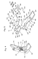
- Fig. 2 is a perspective view which illustrates the automatic document conveying device of Fig. 1 under the condition where the central main portion thereof is at the open position;
- Fig. 3 is a section view illustrating the automatic document conveying device of Fig. 1 under the condition where the central main portion thereof is at the closed position;
- Fig. 4 is a perspective view illustrating a hinge mechanism in the automatic document conveying device of Fig. 1;
- Fig. 5 is a perspective view illustrating, in a disassembled manner, the hinge mechanism in the automatic document conveying device of Fig. 1 and a coupling member of a support base member of the central main portion mounted thereon;
- Fig. 6 is a section view illustrating the hinge mechanism in the automatic document conveying device of Fig. 1 and the support base member of the central main portion mounted thereon;
- Fig. 7 is a side view illustrating the hinge mechanism in the automatic document conveying device of Fig. 1 and the support base member of the central main portion mounted thereon;
- Fig. 8 is a side view illustrating the hinge mechanism in the automatic document conveying device of Fig. 1 and the support base member of the central main portion mounted thereon under the condition where the support base member is opened;
- Fig. 9 is a rear view showing, partly in cross section, the hinge mechanism in the automatic document conveying device of Fig. 1 and the support base member of the central main portion mounted thereon;
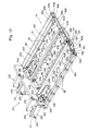
- Fig. 10 is a perspective view illustrating the support base member of central main portion in the automatic document conveying device of Fig. 1 and document conveying means (conveyer belt mechanism) mounted thereon;
- Fig. 11 is a perspective view illustrating, in a disasseembled manner, the support base member of the central main portion in the automatic document conveying device of Fig. 1 and document conveying means (conveyer belt mechanism) mounted thereon;
- Fig. 12 is a plan view illustrating the support base member of the central main portion in the automatic document conveying device of Fig. 1 and document conveying means (conveyer belt mechanism) mounted thereon;
- Fig. 13-A and Fig. 13-B are partial side views showing the front-side support means of the document conveying means (conveyer belt mechanism) in the automatic document conveying device of Fig. 1 under the condition where the overall length thereof is extended (belt is stretched) and under the condition where the overall length thereof is contracted (belt is slackened);
- Fig. 14-A and Fig. 14-B are partial side views showing the rear-side support means of the document conveying means (conveyer belt mechanism) in the automatic document conveying device of Fig. 1 under the condition where the overall length thereof is extended (belt is stretched) and under the condition where the overall length thereof is contracted (belt is slackened); and
- Fig. 15 is a perspective view showing a cover member of the central main portion in the automatic document conveying device of Fig. 1.
- Figs. 1, 2 and 3 illustrate an electrostatic copying machine 2 and an automatic document conveying device generally designated at 4 that is mounted on the electrostatic copying machine 2.
- the electrostatic copying machine 2 which per se may be of a known form is equipped with a nearly parallelopiped housing 6.
- a transparent plate (Figs. 2 and 3) made of a glass which may be of a rectangular shape is disposed at a central portion on the upper surface of the housing 6.
- a document placing-position restricting member 10 is disposed at one end edge of the transparent plate 8 (left end edge in Fig. 3). The document placing-position restricting member 10 extends in a direction perpendicular to the surface of the paper in Fig. 3 along one end edge of the transparent plate 8.
- the housing 6 of the electrostatic copying machine 2 are disposed various constitutional elements including a rotary drum that has an electrostatic photosensitive member on the surface thereof.
- the document to be copied is placed on the transparent plate 8 with its surface to be copied being faced downwards and its one end edge being contacted to an inside edge of the document placing-position restricting member 10 (right end edge in Fig. 3).
- a latent electrostatic image is formed on the rotary drum by the step of forming latent electrostatic image in which the lower surface of the document placed on the transparent plate 8 is optically scanned and is projected onto the rotary drum, and the latent electrostatic image is developed to a toner image which is then transferred onto a copying sheet which may be a common paper. The thus transferred toner image is fixed onto the copying sheet.
- an image-copied sheet is obtained.
- the diagramed automatic document conveying device 4 constituted according to the present invention is made up of a document introduction portion 12, a central main portion 14, and a document delivery and re-introduction portion 16.
- the document introduction portion 12 of the automatic document conveying device 4 is disposed on the upstream side of the transparent plate 8 (left side in Fig. 3) and abuts on the one end edge thereof.
- the document introduction portion 12 includes an introduction portion frame member 18 mounted on the upper surface of the housing 6 of the electrostatic copying machine 2, and a document table 20 that extends to the upstream side from the frame member 18.
- the document table 20 is extended toward the upstream side (toward the left in Fig. 3) being slightly inclined upwards.
- An upstanding stationary document restricting wall 22 is disposed at the rear edge of the document table 20.
- the document table 20 is equipped with a movable document restricting member 24 that per se may be of a known form and that is allowed to move back and forth.
- the movable document restricting member 24 has an upstanding wall 26, and the document placed on the document table 20 is positioned between the stationary document restricting wall 22 and the upstanding wall 26 of the movable document restricting member 24.
- the frame member 18 includes a front supporting member 28, a rear supporting member 30, and a cover member 32 disposed between these supporting members 28 and 30.
- one lower restricting plate 33 and three upper restricting plates 34, 36 and 38 are disposed in a space under the cover member 32 and between the front supporting member 28 and the rear supporting member 30, and a document introduction passage 40 is defined by the lower restricting plate 33 and the upper restricting plates 34, 36 and 38.
- the document sending means 42 includes a document sending roller 46 and a document separation roller pair 48.
- the document sending roller 46 is selectively lowered as indicated by a two-dot chain line from a non-acting position indicated by a solid line, is brought into contact with the upper surface at the downstream end of the uppermost document among a plurality of pieces of documents placed on the document table 20, and is driven in a direction indicated by arrow 50, so that hte document placed on the document table 20 is sent to the document introduction passage 40.
- the document separation roller pair 48 is constituted by a feel roller 52 and a reversing roller 54.
- the reversing roller 54 is selectively positioned between a on-acting position indicated by a solid line and an acting position indicated by a two-dot chain line.
- the reversing roller 54 When located at the non-acting position, the reversing roller 54 is under the feed roller 52 being separated away therefrom. When located at the acting position, the reversing roller 54 is brought into contact with the feed roller 52 to act in cooperation therewith. The feed roller 52 is rotated in a direction indicated by arrow 56, and the reversing roller 54 is rotated in a direction indicated by arrow 58.
- the document separation roller pair 48 separates the uppermost document only from the other documents and introduces it into the document introduction passage 40 while blocking the introduction of other documents.
- the document introduction means 44 is constituted by an upper roller 60 and a lower roller 62 that act in cooperation.
- the upper roller 60 and the lower roller 62 are rotated in a direction indicated by arrow 64, and the document introduced into the document introduction passage 40 is delivered onto the transparent plate 8.
- a placed document detector 66 for detecting a document that is placed on the document table 20
- a plurality of introduced document detectors 68 for detecting a document that is introduced onto the transparent plate 8 via the document introduction passage 40.
- the plurality of introduced document detectors 68 detect the document, i.e., detect the document that is introduced and further detect the size of the introduced document.
- the rear supporting member 30 of the introduction portion frame member 12 is equipped with an introduction portion drive source (Fig. 3) which may be an electric motor.
- the document sending means 42 and the document introduction means 44 in the document introduction portion 12 are driven by the introduction portion drive source 69.
- constitutions of the document sending means 42 (document sending roller 46 and document separation roller pair 48), document introduction means 44 (upper roller 60 and lower roller 62) and placed document detector 66 do not constitute any novel features of the present invention and may be those of the forms known by people having ordinary skill, e.g., may be those of the forms disposed in the specification and drawings of Japanese Laid-Open Patent Publication No. 100939/1990 filed by the present applicant entitled "Automatic Document Conveying Device and Image Processing Machine Equipped Therewith)". Therefore, the specification of this application does not describe their constitutions in detail.
- the central main portion 14 in the automatic document conveying device 4 is equipped with a movable main portion frame member 70.
- the main portion frame member 70 is mounted on the upper surface of the housing 6 of the electrostatic copying machine 2 via a pair of hinge mechanisms 72 (Fig. 2) disposed at the rear side of the transparent plate 8, and can be manually opened or closed between a closed position shown in Figs. 1 and 3 and an open position shown in Fig. 2.
- a pair of hinge mechanisms 72 Fig. 2
- Fig. 2 disposed at the rear side of the transparent plate 8
- a portion of the main portion frame member 70 that covers the transparent plate 8 at the closed position assumes the box-like shape with its lower surface open.
- document conveying means 74 that conveyes the document onto the transparent plate 8 is disposed in the box-like portion of the main portion frame member 70.
- the document conveying means 74 is constituted by a conveyer belt mechanism that includes a driven roller roller 76, a follower roller 78, pushing rollers 80, 82, 84 and 86 disposed maintaining a distance in a direction in which the document is conveyed (right-and-left direction in Fig. 3), and an endless belt 88 wound around these rollers.
- the frame member 70 is equipped with a main portion drive source 89 (Fig.
- the main portion drive source 89 selectively drives the document conveying means 74 either in the normally conveying direction indicated by arrow 90 or in the reversely conveying direction indicated by arrow 92.
- the upper surface of the box-like portion of the main portion frame member 70 constitutes a first document receiving tray 94 that receives the document discharged through the document delivery and re-introduction portion 16 which will be described late.
- the document delivery and re-introduction portion 16 in the automatic document conveying device 4 is disposed on the downstream side (right side in Fig. 3) of the transparent plate 8 and abuts on the other end edge (right end edge in Fig. 3) thereof.
- the document delivery and re-introduction portion 16 includes a box-like delivery portion frame member 100 with its lower surface open.
- the frame member 100 is constituted by front and rear members 102 and 104 disposed in a spaced-apart relationship in the to-and-fro direction (direction perpendicular to the surface of the paper in Fig. 3), side walls 106 and 108 disposed in a spaced-apart relationship in the right-left direction in Fig. 3, and an upper surface wall 110.
- a passage opening 112 (Figs. 2 and 3) through which the document will pass.
- a first discharge opening 114 (Figs. 2 and 3) is formed at the upper end of the side wall 106 and a second discharge opening 116 (Fig. 3) is formed at the upper end of the side wall 108.
- a horizontally extending rotating shaft 118 is rotatably mounted on the central part of the frame member 100, and a plurality of delivery rollers 120 are secured to the rotating shaft 118 in an axially spaced-part relationship.
- the document delivery passage 132 extending from the passage opening 112 includes a common passage 136 as well as a first branched passage 138 and a second branched passage 140.
- the common passage 136 extends from the passage opening 112
- the first branched passage 138 extends from a branch point (downstream end of common passage 136) to the first discharge opening 114
- the second branched passage 140 extends from the above branching point to the second discharge opening 116.
- the re-introduction passage 134 is branched from the first branched passage 138 and extends to the passage opening 112.
- Branched passage switching means 142 is disposed at the branching point of the first and second branched passages 138 and 140, i.e., at the downstream end of the common passage 136.
- the branched passage switching means 142 is selectively positioned at a first branched position indicated by a solid line and at a second branched position indicated by a two-dot chain line. When the branched passage switching means 142 is positioned at the first branched position, the common passage 136 is communicated with the first branched passage 138.
- Discharge re-introduction switching means 144 is disposed at the upstream end of hte re-introduction passage 134 which is branched from the first branched passage 138.
- the discharge re-introduction switching means 144 is selectively positioned at the re-introduction position indicated by a solid line and the discharge position indicated by a two-dot chain line.
- the upstream portion of the first branched passage 138 is shut off from its downstream portion; i.e., the upstream portion of the first branched passage 138 is communicated with the re-introduction passage 134.
- the discharge re-introduction switching means 144 is positioned at the discharge position, the upstream portion of the first branched passage 138 is communicated with its downstream portion, and the re-introduction passage 134 is shut off from the first branched passage.
- a delivery re-introduction switching means 146 in relation to the passage opening 112, i.e.
- the delivery re-introduction switching means 146 is selectively positioned to the delivery position indicated by a solid line and to the re-introduction position indicated by a two-dot chain line.
- the delivery re-introduction switching means 146 is positioned at the delivery position.
- the delivery reintroduction switching means 146 is positioned at the re-introduction position.
- the document delivery means 148 includes, in addition to the delivery rollers 120, follower rollers 150 and 152 cooperating together with the delivery rollers 120, and discharge rollers 154 and 156.
- a plurality of follower rollers 150 are secured to the rotatably mounted and horizontally extending rotating shaft 158 so as to be corresponded to the plurality of delivery rollers 120.
- a plurality of follower rollers 152 are secured to a rotatably mounted and horizontally extending rotating shaft 160 so as to be corresponded to the plurality of delivery rollers 120.
- the discharge rollers 154 disposed in relation to the first branched passage 138 are secured in plural number to a horizontally extending rotating shaft 162 maintaining a spaced-part relationship in the axial direction
- the discharge rollers 156 disposed in relation to the second branched passage 140 are secured in plural number to a horizontally extending rotating shaft 164 maintaining a spaced-apart relationship in the axial direction.
- the delivery portion frame member 100 is provided with a delivery portion drive source 165 (Fig.
- the discharge roller 154 discharges, through the first discharge opening 144, the document that is delivered to the downstream portion of the first branched passage 138.
- the document discharged through the first discharge opening 114 is accommodated in the first document receiving tray 94 formed on the upper surface of the main portion frame member 70.
- the discharge roller 156 discharges, through the second discharge opening 116, the document that is delivered onto the second branched passage 140.
- a second document receiving tray 168 is disposed on the downstream side of the second discharge opening 116, and the document discharged through the second discharge opening 116 is accommodated in the second document receiving tray 168.
- delivered document detecting means 170 that detects the document delivered from the transparent plate 8 to the common passage 136 of the document delivery passage 132
- first discharged document detecting means 172 that detects the document discharged onto the first document receiving tray 94 via the first branched passage 138
- second discharged document detecting means 174 that detects the document discharged onto the second document receiving tray 168 via the second branched passage 140
- re-introduced document detecting means 175 that detects the document re-introduced onto the transparent plate 8 via the re-introduction passage 134.
- These detecting means 170, 172, 174 and 175 may be constituted by using microswitches or photoelectric switches.
- the document delivery and re-introduction portion 16 does not constitute any novel feature of the present invention and may, hence, be those of the forms disclosed in detail in the specification and drawings of U. S. Patent Application Serial No. 07/550853 filed on July 10, 1990 or European Patent Application No. 90113174.8 filed on July 10, 1990 corresponding to Japanese Patent Application No. 175523/1989 (filed July 10, 1989 entitled Automatic Document Conveying Device) filed by the present applicant. Therefore, they are not described in detail in the specification of the present application.
- the above-mentioned automatic document conveying device 4 conveys the document in any one of a simple mode, a reversing mode or a double reversing mode. If described with reference of Fig. 3, when the simple mode is selected, the document on the document table 20 is introduced onto the transparent plate 8 via the document introduction passage 40 and is placed at a predetermined position (where the trailing end of the document is in contact with the document position restricting member 10) on the transparent plate 8. Then, the electrostatic copying machine 2 effects the scanning and exposure for one surface (lower surface) of the document. The document is then discharged onto the first document receiving tray 94 via the common passage 136 and the first branched passage 138 in the document delivery passage 132.
- the document on the document table 20 is introduced onto the transparent plate 8 via the document introduction passage 40 and is placed at a predetermined position on the transparent plate 8. Then, the electrostatic copying machine 2 effects the scanning and exposure for one surface of the document.
- the document on the transparent plate 8 then enters into the first branched passage 138 from the common passage 136 of the document delivery passage 132, and is introduced into the re-introduction passage 134 from the first branched passage 138. Consequently, the document is reversed its front surface back and is placed at a predetermined position on the transparent plate 8.
- the electrostatic copying machine 2 then effects the scanning and exposure for the other surface of the document which has been reversed front surface back.
- the document is discharged onto the second document receiving tray 168 via the common passage 136 and the second branched passage 140 of the document delivery passage 132.
- the document introduced onto the transparent plate 8 from the document table 20 via the document introduction passage 40 is not positioned on the transparent plate 8 but is kept conveyed onto the common passage 136 of the document delivery passage 132, and is re-introduced onto the transparent plate 8 via the first branched passage 138 and the re-introduction passage 134 and is placed at a predetermined position on the transparent plate 8 after it is reversed front surface back.
- the electrostatic copying machine 2 then executes the scanning and exposure for one surface (lower surface) of the document.
- the document is then re-introduced onto the transparent plate 8 from the transparent plate 8 via the common passage 136 and the first branched passage 138 of the document delivery passage 132 and the re-introduction passage 134.
- the document is then reversed again front surface back and is placed again at the predetermined position on the transparent plate 8.
- the electrostatic copying machine 2 then executes the scanning and exposure for the other surface of the document.
- the document is then discharged onto the first document receiving tray 94 via the common passage 136 and first branched passage 138 of the document delivery passage 132.
- the central main portion 14 that includes the movable main portion frame member 70 and the document conveying means (conveyer belt mechanism) 74 mounted thereon, is constituted quite separately from the document introduction portion 12 and the document delivery and re-introduction portion 16. No mutual action of driving force or no mutual action of pressing force exists between the main portion 14 and the document introduction portion 12 or between the main portion 14 and the document delivery and re-introduction portion 16.
- the introduction portion drive source 69, main portion drive source 89 and delivery portion drive source 165 are arranged in the document introduction portion 12, main portion 14 and document delivery portion 16, respectively, and there does not quite exist any drive coupling relationship between the main portion 14 and the document introduction portion 12 or between the main portion 14 and the document delivery portion 16. Furthermore, the pair of rollers that press each other and that work in cooperation togethr are not so disposed that one of them exists on the main portion 14 and the other one exists on the document introduction portion 12 or the document delivery and re-introduction portion 16. Therefore, no mutually pressing relationship exists at all between the main portion 14 and the document introduction portion 12 or between the main portion 14 and the document delivery and re-introduction portion 16.
- the movable main portion frame member 70 of the main portion 14 and the document conveying means (conveyer belt mechanism) 74 are not adversely affected by the driving force or the pressing force and are stably placed at the required position with respect to the transparent plate 8 maintaining sufficiently high precision.
- the central main portion 14 includes the movable main portion frame member 70 and the document conveyer means (conveyer belt mechanism) 74 mounted on the main portion frame member 70.
- the main portion frame member 70 is mounted on the upper surface of the housing 6 of the electrostatic copying machine 2 by a pair of hinge mechanisms 72 disposed maintaining a distance in the conveying direction so as to pivot between the closed position shown in Figs. 1 and 3 and the open position shown in Fig. 2.
- each of the pair of hinge mechanisms 72 which per se may be of a known form has a stationary member 180 and a pivoting member 182.
- the stationary member 180 has a bottom wall 184 and a pair of upright support walls 186 that extend upwardly from both side edges of the bottom wall.
- the stationary member 180 is secured to a predetermined position on the upper surface of the housing 6 by screwing the fastening screws 188 (Fig. 6) into the upper wall of the housing 6 of the electrostatic copying machine 2 through the bottom wall 184.
- Each of the pair of upright support walls 186 has mounting holes 190 and 192.
- the pivoting member 182 has an upper wall 194 and a pair of side walls 196 that hang downwardly from both side edges of the upper wall 194.
- a hole 198 is formed at a rear end of the upper wall 194.
- a mounting hole 200 is formed at the rear end of each of the side walls 196, and a mounting hole 202 is formed at the front end of each of the side walls 196.
- an L-shaped notch 204 is formed in the middle portion of each of the side walls 196 extending upwardly from the lower edge thereof and then extending rearwardly. As shown in Fig.
- a coupling pin 205 is jointly inserted to the mounting holes 190 formed in the upright support walls 186 of the stationary member 180 and to the mounting holes 200 formed in the side walls 196 of the pivoting member 182, whereby the pivoting member 182 is pivotably mounted on the stationary member 180 with the pin 205 as a center.
- Both ends of a pin 206 are pivotably fitted to the mounting holes 192 formed in the pair of upright support walls 186 of the stationary member 180.
- To the pin 206 are fixed two cylindrical members 208 that protrude substantially perpendicularly from the central portion thereof.
- both ends of a pin 210 are inserted in the notches 204 formed in both side walls 196 of the pivoting member 182.
- Compression coil springs 214 are fitted to the round rod members 212 of the pin 210, and the round rod members 212 of the pin 210 are slidably inserted in the cylindrical members 208 of a pin 206.
- the coil springs 214 are positioned between the pin 210 and the cylindrical members 208, and work to resiliently urge the pivoting member 182 in the counterclockwise direction as viewed from the left front side in Fig. 4.
- the pivoting member 182 pivots relative to the stationary member 180, the round rod members 212 slide relative to the cylindrical members 208.
- the movable main portion frame member 70 mounted on the upper surface of the housing 6 via the pair of hinge mechanisms 72 includes a support base member 216 and a cover member 218 (Figs. 1 to 3 and 15) mounted on the support base member 216.
- the support base member 216 has a pair of coupling members 220 and a pair of support plates 222 secured to the coupling members 220, respectively.
- each of the pair of coupling members 220 has a bottom wall 224 and upright side walls 226 that upwardly extend from both side edges of the bottom wall 224.
- Rectangularly protruded pieces 228 are formed outwardly protruding in the lateral direction from the upper edges at the rear portion of the side walls 226.
- a mounting hole 230 is formed in the middle portion of the side walls 226.
- a protruded piece 229 is laterally protruded from the rear end of one of the side walls 226 (side wall 226 positioned on the left front side of Fig. 5), and a threaded hole 231 is formed in the protruded piece 229.
- the coupling member 220 is disposed on the underside of the pivoting member 180 of the hinge mechanism 72, and the side walls 226 of the coupling member 220 are positioned on the outside of the side walls 196 of the pivoting member 180.
- a mounting pin 232 is jointly inserted to the mounting holes 230 formed in the side walls 226 of the coupling member 220 and to the mounting holes 202 formed in the front end of side walls 196 of the pivoting member 180, whereby the coupling member 220 of the support base member 216 is pivotably mounted on the pivoting member 180 of the hinge mechanism 72 with the pin 232 as a center.
- the rear end portions of the support plates 222 are fixed to the front end portions of the coupling members 220.
- Three holes 234 are formed in the front end portion of the coupling member 220, and corresponding three threaded holes 236 (Fig. 11) are formed in the rear end portion of the support plate 222 that is positioned under the front end portion of the coupling member 220.
- Coupling screws (not shown) are screwed into the threaded holes 236 via the holes 234 so that the rear end portion of the support plate 222 is secured to the front end portion of the coupling member 220.
- the support plate 222 is secured to the front end portion of the coupling portion 220, and extends forward from its cantilevered rear end portion.
- the support plates 222 in the diagramed embodiment are made of an extrusion-molded aluminum material and have a channel shape with a band plate portion 238 and both side walls 240 that upwardly extend from both side edges of the band plate portion 238.
- the movable main portion frame member 70 that can be manually pivoted to open or close should have a weight as light as possible to facilitate the opening and closing. It is therefore desired to decrease the weight of the support plate 222 of the support base member 216 as light as possible.
- the document conveying means (conveyer belt mechanism) 74 is mounted on the support base member 216, and the support plate 222 should have a strength enough to support the document conveying means 74.
- the support plate 222 extends forward from the cantilevered rear end portion thereof. Therefore, the required geometrical moment of inertia of the support member 222 gradually increases from the front end toward the rear portion thereof or, in other words, the geometrical moment of inertial gradually decreases from the rear end toward the front portion thereof, enabling the support member 222 to exhibit strength enough for supporting the document conveying means 74.
- the support plate 222 according to the present invention is so formed as to exhibit a geometrical moment of inertia that decreases toward the front portion from the rear portion thereof, in order to decrease the weight yet maintaining a required strength of the support plate 222.
- the support plate 222 has a plurality of weight-reducing openings 242 formed in the lengthwise direction of the support plate 222 maintaining suitable distances in order to reduce the weight of the support plate 222.
- the openings 242 are small in the rear portion and become larger toward the front portion. Therefore, the geometrical moment of inertia decreases from the rear portion of the support member 222 toward the front portion thereof. It is also allowable to suitably change the number of the openings instead of, or in addition to, changing the size of the openings 242.
- the amount of upward protrusion of the side walls 240 of the support plate 222 may be decreased from the rear portion toward the front portion in order to decrease the geometrical moment of inertia of the support plate 222 from the rear portion toward the front portion thereof.
- positioning contact pieces 244 and 246 are fastened by the fastening screws 248 and 250 to the rear end portion and the front end portion of the pair of support plates 222 of the support base member 216.
- a rectangular opening 252 is formed in the front end portion of the coupling member 220 of the support base member 216, and the contact piece 244 is secured to the rear end portion of the support plate 222 through the opening 252.
- the contact pieces 244 and 246 have downwardly extending legs. The legs of the contact pieces 244 downwardly protrude through the openings 254 formed in the rear portion of the support plates 222, and the legs of the contact pieces 246 downwardly protrude through the notches 256 formed in the front end of the support plates 222.
- a slender pressing plate 258 is disposed extending in the conveying direction and spanning across the pair of coupling members 220 on the rear end portions (portions at the back of the protruded pieces 228) of upper edges of side walls 226 of the pair of coupling members 220 of the support base member 216.
- the pressing plate 258 are formed holes 260 corresponding to the holes 198 formed in the upper walls 194 of the pivoting members 182 of the pair of hinge mechanisms 72.
- Bolts 262 protrude upwardly through the holes 194 of the pivoting members 182 and the holes 260 of the pressing plates 258. The head of the bolt 262 is anchored to the lower surface of the upper wall 194 of the pivoting member 182.
- a compression spring 264 is fitted to the bolt 262 to constitute resiliently urging means.
- a restricting plate 266 is disposed extending in the conveying direction and spanning across the two coil springs 264 at an upper position thereof. Holes 268 are formed at both ends of the restricting plate 266, and the bolts 262 upwardly protrudes through these holes 268. Nuts 270 are screwed to the ends of the bolts 262.
- the compression springs 264 resiliently urge the coupling members 220 of the support base member 216 in the clockwise direction in Fig. 6 with respect to the pivoting members 182 of hinge, mechanisms 72.
- the resilient urging force of the compression coil springs 264 can be suitably adjusted by adjusting the nuts 270 screwed to the bolts 262.
- the document conveying means (conveyer belt mechanism) 74 is mounted on the support base member 216, and the cover member 218 is further mounted thereon as will be described later.
- the weight of the support base member 216 and of the constitutional elements mounted thereon, i.e., the acting center of weight or the center of gravity G of the central main portion 14, is located considerably in front of the position where the pivoting members 182 of the hinge mechanisms 72 are pivotably coupled to the coupling members 220 of the support base member 216, i.e., located considerably in front of the position of center axis of the mounting pin 232 (the center of gravity G of the central main portion 14 can be brought into agreement with the center axis of the mounting pin 232 by excessively forwardly extending the pivoting members 182 of the hinge mechanisms 72, but this results in an increase in the size, weight and cost of the hinge mechanisms 72).
- the compression coil springs 264 give a resiliently urging force to the support base member 216 in the counterclockwise direction in Fig. 6.
- the magnitude of the resiliently urging force is set to such a value that the support base member 216 or the central main portion 14 receives a balancing moment of rotation in the counterclockwise direction that nearly corresponds to the above-mentioned moment of rotation in the clockwise direction caused by the weight of the central main portion 14 under the condition where the central main portion 14 is located at the closed position shown in Fig. 6.
- the document conveying means 74 is reliably prevented from being pivoted from the desired position.
- brake mechanisms 272 are disposed being related to the pair of hinge mechanisms 72.
- Each of the brake mechanisms 272 is constituted by a stationary brake piece 274 and a swingable brake piece 276.
- the stationary brake piece 274 that can be made of a suitable synthetic resin is secured by a set-screw 278 (Fig. 7) to the outer surface of one of the pair of upright support walls 186 (upright support wall 186 of the right upper side in Fig. 5) of the stationary member 180 of the hinge mechanism 72.
- a first arcuate inner peripheral surface 280 and a second arcuate inner peripheral surface 282 are formed on the upper surface of the stationary brake piece 274.
- the second arcuate inner peripheral surface 282 is slightly displaced toward a direction to be separated away from the pivotable brake piece 276, and an intermediate step portion 284 is formed between them. Further, a front step portion 286 is formed on the front side (right side in Figs. 7 and 8) of the first arcuate inner peripheral surface 280.
- the pivotable brake piece 276 that can likewisely be made of a suitable synthetic resin is secured by a set-screw 288 (Fig. 7) to the lower edge portion at the rear end of one of the pair of side walls 226 (side wall 226 of the right upper side in Fig.
- the pivotable brake piece 276 has an arcuate outer peripheral surface 290 formed at a rear portion on the lower surface thereof.
- the arcuate outer peripheral surface 290 of the pivotable brake piece 276 is forcibly pressed onto the first arcuate inner peripheral surface 280 of the stationary brake piece 274 due to the balancing moment of rotation, and due to the frictional force between the two, the braking force acts on the pivoting motion of the central main portion 14.
- the braking action is exerted on the central main portion 14 which pivots to open or close within a range of the first arcuate inner peripheral surface 280 between the front step portion 286 and the intermediate step portion 284 of the stationary brake piece 274 (within a range of about 20° to 75° of opening angle from the closed position of the central main portion 14), and the central main portion 14 is maintained at any angular position desired by the operator.
- the braking force is relatively small and the force for holding the central main portion 14 is relatively small, too.
- the arcuate outer peripheral surface 290 of the pivotable brake piece 276 passes over the intermediate step portion 284 and is pressed onto the second arcuate outer peripheral surface 282 as indicated by a two-dot chain line in Fig. 8.
- the coupling member 220 is turned by some angle (which may correspond to the aforementioned angle ⁇ ) in the clockwise direction in Fig. 8 with the mounting pin 232 as a center.
- the document conveying means 74 constituted by the conveyer belt mechanism is mounted on the support base member 216 of the main portion frame member 70 in the central main portion 14.
- the document conveying means 74 includes front-side support means 292 and rear-side support means 294.
- the front-side support means 292 has a driven-side support member 296 and a follower-side support member 298 and, similarly, the rear-side support means 294 has a driven-side support member 300 and a follower-side support member 302.
- the driven-side support member 296 of the front-side support means 292 is constituted by a slender plate member that extends in the conveying direction (up-and-down direction in Fig. 12).
- Threaded holes 304 are formed in the front ends at the upper end portions of both side walls of the pair of support members 222 in the support base member 216, and four mounting holes 306 are formed in the driven-side support member 296 to correspond thereto.
- Set-screws 308 are screwed into the threaded holes 304 through the mounting holes 306, whereby the driven-side support member 296 is secured to the front end of the support plate 222.
- the follower-side support member 298 of the front-side support means 292 is constituted by a plate member that extends in the conveying direction.
- the follower-side support member 298 is mounted on the driven-side support member 296 to move over a required range in the conveying direction. Referring, further, to Figs.
- a forwardly protruded guide pin 310 and a lock pin 312 are studded on the driven-side support member 296 at the follower-side end (left lower end in Fig. 11).
- a guide slot 314 and a lock slot 316 are formed in the follower-side support member 298.
- the guide slot 314 extends in the conveying direction.
- the lock slot 316 has a relative movement-permitting portion 318 that extends in the conveying direction and a lock portion 320 that extends nearly perpendicularly to the conveying direction.
- the guide pin 310 is inserted in the guide slot 314 and the lock pin 312 is inserted in the lock slot 316, so that the follower-side support member 298 is mounted on the driven-side support member 296.
- the driven-side support member 298 has an engaging piece 319 that forwardly protrudes from the upper edge thereof and a grip piece 321 that extends forward from the lower edge thereof.
- resiliently urging means 322 constituted by a pulling spring is provided between the guide pin 310 of the driven-side support member 296 and the engaging piece 319 of the follower-side support member 298.
- the guide pin 310 moves in the conveying direction in the guide slot 314, so that the lock pin 312 moves in the conveying direction in the relative movement-permitting portion 318 of the lock slot 316, and the driven-side supporting member 298 is allowed to move in the conveying direction with respect to the driven-side support member 296.
- Resiliently urging means 322 resiliently urges the driven-side support member 298 leftwardly in Fig. 13-A, i.e., toward the direction to extend the full length of the front-side support means 292 defined by the driven-side support member 296 and the driven-side support member 298 in the conveying direction.
- a driven roller 76 and a follower roller 78 are mounted between the front-side support means 292 and the rear-side support means 294 maintaining a distance in the conveying direction, and an endless belt 88 is wound round the driven roller 76 and the follower roller 78.
- the endless belt 88 is maintained under the stretched condition due to the resiliently urging action by the resiliently urging means 322 (under this condition, the full length between the driven-side support member 296 and the follower-side support member 298 is not the possible greatest length but is slightly shorter than it).
- the grip piece 321 formed in the followe-side support member 298 is gripped or is touched by a finger, and the follower-side support member 298 is moved by a predetermined length rightwards in Figs. 13-A and 13-B, i.e., toward the direction to shorten the full length of the front-side support means 292 defined by the driven-side support member 296 and the follower-side support member 298 against the resiliently urging action of the resiliently urging means 322. Then, the right end portion of the follower-side support member 298 is slightly moved downwardly in Figs. 13-A and 13-B, so that the lock pin 312 is positioned in the lock portion 320 of lock slot 316 as shown in Fig. 13-B.
- a driven-side support member 300 of the rear-side support means 294 is also constituted by a plate-like member that extends in the conveying direction.
- the height of the driven-side support member 300 of the rear-side support means 294 in the up-and-down direction is considerably greater than the height in the up-and-down direction of the driven-side support member 296 of the front-side support means 292.
- Threaded holes are formed in the upper rear ends of both side walls of the pair of support plates 222 in the support base member 216, and four mounting holes 324 are formed in the driven-side support member 300 to correspond thereto.
- the driven-side support member 302 of the rear-side support means 294, too, is constituted by a plate-like member that extends in the conveying direction, and its height in the up-and-down direction is considerably greater than the height in the up-and-down direction of the follower-side support member 298 of the front-side support means 292.
- the follower-side support member 302 is mounted on the driven-side support member 300 to move over a required range in the conveying direction. If described with reference to Figs. 10 and 11, and Figs.
- a rearwardly protruding guide pin 325 and a lock pin 326 are studded on the driven-side support member 300 at the follower-side ends (left lower end portions in Fig. 11).
- An expanded head is formed at the protruded end of the guide pin 325.
- a guide slot 328 and a lock slot 330 are formed in the follower-side support member 302.
- the guide slot 328 extends in the conveying direction and the end of its driven side is open.
- the lock slot 330 has a relative movement-permitting portion 332 extending in the conveying direction and a lock portion 334 extending nearly perpendicularly to the conveying direction.
- the guide pin 325 is inserted in the guide slot 328 and the lock pin 326 is inserted in the lock slot 330, so that the follower-side support member 302 is inserted in the driven-side support member 300.
- the driven-side support member 300 has an engaging piece 336 that forwardly protrudes from the lower edge thereof, and the follower-side support member 302 has an engaging piece 338 that forwardly protrudes from the lower edge thereof.
- the follower-side support member 302 further has a grip piece 340 (Figs. 11 and 12) that rearwardly extends from the lower edge thereof. As clearly shown in Figs.
- resiliently urging means 342 constituted by a pulling spring is disposed between the engaging piece 336 of driven-side support member 300 and the engaging piece 338 of follower-side support member 302.
- the resiliently urging means 342 resiliently urges the follower-side support member 302 toward the left in Fig. 14-A, i.e., toward the direction to extend in the conveying direction the full length of the rear-side support means 294 that is defined by the driven-side support member 300 and the follower-side support member 302.
- the endless belt 88 (Figs. 2 and 3) is maintained under the stretched condition by the resiliently urging action of the resiliently urging means 342 (under this condition, the full length between the driven-side support member 300 and the follow-side support member 302 is not the possible greatest length but is slightly shorter than it).
- the grip piece 340 of the follower-side support member 302 is'gripped or is touched by finger, and the follower-side support member 302 is moved by a predetermined length toward the right in Figs. 14-A and 14-B, i.e., toward the direction to shorten the full length of the rear-side support means 294 defined by the driven-side support member 300 and the follower-side support member 302 against the resiliently urging action of the resiliently urging means 342. Then, the right end portion of the follower-side support member 302 is slightly moved downwards in Figs. 14-A and 14-B, so that as shown in Fig. 14-B, the lock pin 326 is positioned in the lock portion 334 of lock slot 330.
- the follower-side support member 302 is then prevented, by the action of the resiliently urging means 342, from returning to the left in Fig. 14-B, and is locked under the full-length contracted condition that is shown in Fig. 14-B (thus, the lock pin 326 and the lock slot 330 work in cooperation to constitute locking means). If the right end portion of the follower-side support member 302 is slightly moved upwards in Figs. 14-A and 14-B so that the lock pin 326 is positioned in the relative movement-permitting portion 332 of lock slot 330, the locking action is released and the follower-side support member 302 is returned back to the condition shown in Fig. 14-A owing to the action of the resiliently urging means 342.
- a shaft member 348 is rotatably fitted via bearing sleeves 344 and 346 between one end (upper end portion of Fig. 12) of the driven-side support member 296 of the front-side support means 292 and one end (upper end portion in Fig. 12) of the driven-side support member 300 of the rear-side support means 294, and a driven roller 76 that continuously extends in the direction of width (right-and-left direction in Fig. 12) is secured to the shaft member 348. Furthermore, a shaft member 354 is rotatably fitted via bearing sleeves 350 and 352 between one end (lower end portion in Fig.
- the driven-side support member 296 and the follower-side support member 298 constituting the front-side support means 292 have a size in the up-and-down direction which is smaller than the diameters of the driven roller 76 and of the follower roller 78, and the upper running portion and the lower running portion of the endless belt 88 wound round the driven roller 76 and the follower roller 78 are positioned over and under the driven-side support member 296 and the follower-side support member 298, respectively.
- a belt locking member 355 (Figs. 11 and 12) is mounted on one end (upper end portion in Fig. 12) of the driven-side support member 296 of the front-side support means 292.
- the belt locking member 355 that may be made of a suitable synthetic resin has an inside shape that corresponds to the outer at one end of the driven-side support member 296, and is detachably and resiliently engaged with one end of the driven-side support member 296.
- a locking flange 357 On the inside of the belt locking member 355 is formed a locking flange 357 that is positioned opposed to one side edge of the endless belt 88 and that prevents the endless belt 88 from moving forward.
- a grip piece 359 that can be gripped by hand at the time when the belt locking member 355 is to be mounted on, or removed from, the driven-side support member 296. If further described with reference to Figs.
- the aforementioned pressing rollers 80, 82, 84 and 86 are mounted between the front-side support means 292 and the rear-side support means 294.
- shaft mounting members 356 are secured by set-screws 358 to the upper surface at the front end and rear end of the pair of support members 222 in the support base member 216.
- the shaft mounting members 356 have a box-like portion with its inside in the direction of width being open.
- a shaft member 360 having pressing rollers 80 fastened thereto maintaining a distance in the axial direction and a shaft member 362 having pressing rollers 82 fastened thereto maintaining a distance in the axial direction, are rotatably inserted at their both ends in the bearing members 364 which are accomodated in the box-like portions of the shaft mounting members 356 and can move up and down.
- the bearing member 364 has an engaging protrusion 366 that protrudes upwardly, and a compression spring 368 that constitutes resiliently urging means is fitted to the engaging protrusion.
- the compression spring 368 is interposed between the bearing member 364 and the upper wall of the box-like portion of the shaft mounting member 356, and resiliently urges the shaft members 360 and 362 downwardly, i.e., urges the pressing rollers 80 and 82 downwardly. Openings 370 and 372 are formed in the band plate portion 238 of the pair of support plates 222 to correspond to the pressing rollers 80 and 82 which are, therefore, allowed to downwardly protrude through these openings 370 and 372. As clearly shown in Fig. 3, the pressing rollers 80 and 82 act on the lower running portion of the endless belt 88 to press it onto the transparent plate 8 of the electrostatic copying machine 2.
- a rearwardly protruded support piece 374 is formed on the driven-side support member 296 of the front-side support means 292, and a forwardly protruded support piece 376 is formed on the driven-side support member 302 of the rear-side support means 294 to correspond thereto.
- a pair of shaft mounting members 378 are secured by set-screws 379 to each of these support pieces 374 and 376 maintaining a distance in the conveying direction.
- the shaft mounting members 378 may be constructed in the same manner as the aforementioned shaft mounting members 356, and have a box-like portion with its inside in the direction of width (right-and-left direction in Fig. 12) being open.
- the shaft member 380 having pressing rollers 84 fixed thereto maintaining a distance in the axial direction and the shaft member 382 having pressing rollers 86 fixed thereto maintaining a distance in the axial direction, are rotatably inserted at their both ends in the bearing members 384 which are accomodated in the box-like portions of the shaft mounting members 378 and can move up and down.
- the shaft member 380 and pressing rollers 84 fixed thereto as well as the shaft member 382 and pressing rollers 86 fixed thereto, are downwardly urged by their own weight and act on the lower running portion of the endless belt 88 to press it onto the transparent plate 8 of the electrostatic copying machine 2.
- the pressing rollers 84 and 86 positioned at the central portion of the conveyer belt mechanism in the conveying direction have a diameter larger by more than a predetermined amount than the diameter of the driven roller 76 and the follower roller 78, and are sufficiently greater than the size in the up-and-down direction of the support plates 222 disposed on both sides of the pressing rollers 84 and 86.
- the uppermost portions of the pressing rollers 84 and 86 pressed onto the transparent plate 8 via the endless belt 88 are substantially equal to, or are slightly higher than, the uppermost portions of the driven roller 76 and the follower roller 78.
- the driven roller 76 is rotated in a direction to take up the upper running portion of the endless belt 88. Therefore, the upper running portion of the endless belt 88 is maintained under the stretched condition.
- the endless belt 88 is driven in a direction indicated by arrow 92 in Fig. 3, however, the driven roller 76 is rotated in a direction to forward the endless belt 88. Therefore, the upper running portion of the endless belt 88 is slackened and its central portion deflects downwardly to some extent.
- the pressing rollers 84 and 86 positioned at the central portion in the conveying direction have a diameter larger by more than a predetermined amount than the diameter of the driven roller 76 and the follower roller 78, and are sufficiently larger than the size in the up-and-down direction of the support plates 222 that are arranged on both sides of the pressing rollers 84 and 86, as mentioned above. Even when the central portion of the upper running portion of the endless belt 88 is downwardly slackened to a considerable degree in the conveying direction, the endless belt 88 is reliably prevented from coming in contact with the stationary support plates 222 and so is effectively prevented from wearing. If described with refrence to Fig.
- a support bracket 386 is secured to the rear surface of the driven-side support member 300 of the rear-side support means 294.
- the main portion drive source 89 which may be a reversible electric motor is mounted on the support bracket 386.
- a toothed pulley 388 is fastened to the output shaft of the main portion drive source 89.
- a shaft member 390 is rotatably fitted between the driven-side support member 300 and the support bracket 386, and toothed pulleys 392 and 394 are fixed to the shaft member 390.
- the rear end portion of the shaft member 348 to which the driven roller 76 is fastened protrudes rearwardly penetrating through the driven-side support member 300, and has a toothed pulley 396 fixed thereto.
- a toothed endless belt 398 is wound round the toothed pulley 388 and the toothed pulley 392, and a toothed endless belt 400 is wound round the toothed pulley 394 and the toothed pulley 396.
- the driven roller 76 of the conveyer belt mechanism is coupled to the main portion drive source 89, and the conveyer belt mechanism is driven by the main portion drive means 89.
- a cover member 218 is mounted on the support base member 216 and on the conveyer belt mechanism that is mounted thereon; i.e., the conveyer belt mechanism is covered with the cover member 218.
- the endless belt 88 in the conveyer belt mechanism will be fouled or damaged after used for extended period of time. In such a case, the endless belt 88 must be renewed, and the following operation may be carried out to replace the endless belt 88.
- the cover member 218 is removed.
- the belt locking member 355 is removed from one end portion of the driven-side support member 296 of the front-side support means 292.
- the follower-side support member 298 in the front-side support means 292 is operated as mentioned above, and the driven-side support member 296 and the follower-side support member 298 in the front-side support means 292 are locked under the full-length contracted condition as shown in Fig. 13-B.
- the follower-side support member 302 in the rear-side support means 294 is operated as described above, and the driven-side support member 300 and the follower-side support member 302 in the rear-side support means 294 are locked under the full-length contracted condition as shown in Fig. 14-B.
- the driven roller 76 and the follower roller 78 are brought close to each other, and the endless belt 88 is shifted to be placed under the slackened condition from the stretched condition. It is therefore allowed to very easily pull out the endless belt 88 forward to remove it.
- the driven-side support member 296 and the follower-side support member 298 of the front-side support means 292 have a size in the up-and-down direction which is so small as will not interrupt the endless belt 88 from being pulled out forward. Then, a new endless belt 88 is moved from the front toward the rear, and is wound round the driven roller 76, follower roller 78, and pressing rollers 80, 82, 84 and 86 to load it.
- the driven roller 76 and the follower roller 78 are maintained under the condition where they are brought close to each other, and it is allowed to very easily load the new endless belt 88 as required. Then, through the aforementioned operation for the rear-side support means 294, locking under the full-length contracted condition is released, and the driven-side support member 300 and the follower-side support member 302 in the rear-side support means 294 are placed under the condition (shown in Fig. 14-A) where they are resiliently urged toward extending the full length thereof due to the action of the resiliently urging means 342.
- the driven-side support member 296 and the follower-side support member 298 in the front-side support means 292 are placed under the condition (shown in Fig. 13-A) where they are resiliently urged toward extending the full length thereof due to the action of the resiliently urging means 322.
- the newly mounted endless belt 88 is stretched by the resiliently urging action of the resiliently urging means 322 and 342.
- the belt locking member 355 is mounted again no one end of the driven-side support member 296 in the front-side support member 292.
- the cover member 218 is mounted as required.
- the above-mentioned operation for replacing the endless belt 88 can be very easily carried out by one person.
- the movable main portion frame member 70 of the central main portion 14 includes, as described already the cover member 218 that covers the document conveying means (conveyer belt mechanism) 74.
- protruded pieces 229 are formed at the rear end of one side wall 226 of the pair of coupling members 220 in the support base member 216 of the movable main portion frame member 70, and a threaded hole 231 is formed in the protruded pieces 229.
- a pair of slots or holes are formed in the rear wall of the cover member 218 to correspond to the threaded holes 231.
- the driven-side support member 296 of the front-side support means 292 in the document conveying means 74 has support protrusions 402 and 404 that protrude forward from the upper edge of the support member 296.
- a hole 406 is formed in one end portion (right upper end in Fig. 10) of the support protrusion 402, and a hole 408 is formed in the support protrusion 404.
- a pair of coupling blocks are fastened to the inner surface of the upper wall of cover member 218 to correspond to the holes 406 and 408, and a threaded hole is formed in each of the coupling blocks.
- Set-screws are screwed into the threaded holes in the coupling blocks through the holes 406 and 408, and the front portion of upper wall of the cover member 218 is fastened to the driven-side support member 296 and is, hence, fastened to the support base member 216 via the driven-side support member 296.
- the cover member 218 has a high bulging portion 410 located at the rear end portion thereof and a low box-like portion 412 that extends forward from the bulging portion 410.
- the high bulging portion 410 is relatively high and the low box-like portion 412 is relatively low.
- the upper surface of the low box-like portion 412 that covers the document conveying means (conveyer belt mechanism) 74 constitutes the document receiving tray 94.
- An upright wall 414 is formed at one edge (right upper side edge in Fig. 15) of the low box-like portion 412. As will be understood with reference to Fig. 1, the upright wall 414 upwardly extends to slightly under the first discharge opening 114 in the document delivery and re-introduction portion 16.
- Recessed portions 416, 418 and 420 are formed in the rear portion, the other edge portion (left lower side edge in Fig. 10) and the front portion on the upper surface of the low box-like portion 412 (in other words, the upper surface of the low box-like portion 412 is bulged in the areas other than recessed portions 416, 418 and 420, and the amount of the bulging gradually increases toward the direction indicated by arrow 422).
- the document placed on the document table 20 of the document introduction portion 12 is positioned with its trailing edge being in contact with or very close to the upright stationary document restricting wall 22 irrespective of its size in the direction of the width, covered through the central main portion 14 and the document delivery and re-introduction portion 16 while maintaining its position in the direction of the width, and is discharged onto the document receiving tray 94 in a direction indicated by arrow 422 through the first discharge port 114 of the document delivery and re-introduction portion 16.
- the rear edge of the document receiving tray 94 i.e., the rear edge of the low box-like portion 412 is substantially in match with the restricting surface of the upright stationary document restricting wall 22 and forms a reference position in the direction of width of the document.
- the recessed portion 416 formed in the rear portion of the document receiving tray 94 has a triangular shape as viewed from the upper direction and has a width that gradually increases in the document delivering direction indicated by arrow 422 from a reference position of the document in the direction of width (i.e., rear edge of the document receiving tray 94) toward nearly the center of the document receiving tray 94 in the direction width.
- the document receiving tray 94 has a protuberance 424 that extends in front of, and being close to, the front edge of the triangular recessed portion 416.
- the protuberance 424 extends forwardly toward the downstream side in the document delivering direction indicated by arrow 422, i.e., extends being tilted from the side of reference position of the document in the direction of width toward the central side in the direction of width.
- a document stop piece 426 is mounted on the protuberance 424 to move therealong, and the protuberance 424 constitutes guide means for the document stop piece 426 which has a base portion 428 and an upright portion 430.
- an engaging groove 431 that works in cooperation with the protuberance 424. With the engaging groove 431 being engaged with the protrusion 424, the document stop piece 426 is mounted to move along the protuberance 424.
- the engaging groove too, is tilted in the same direction as the protuberance 424, and the document stop piece 426 is allowed to move along the protuberance 424 with its upright portion 430 always maintaining a perpendicular relationship with respect to the document conveying direction indicated by arrow 422.
- the document stop piece 426 is manually moved to a desired position depending upon the size of the document discharged from the first discharge opening 114 of the document delivery and re-introduction portion 16. If mentioned in further detail, the document stop piece 426 is so positioned that a distance between the upright portion 430 of the document stop piece 426 and the first discharge opening 114 is nearly brought into agreement with the size in the conveying direction of the document discharged from the first discharge opening 114. The document discharged from the first discharge opening 114 comes in collision at its leading edge with the upright portion 430 of the document stop piece 426, ceases to move, and is collected as desired on the document receiving tray 94.
- the document has a size in the conveying direction that is corresponded to the size in the direction of width of the document.
- the document having a relatively large size in the conveying direction has a size that is relatively large in the direction of width thereof, while the document having a relatively small size in the conveying direction has a size that is relatively small in the direction of width thereof.
- the document stop piece 426 may be moved in the direction indicated by arrow 422 to cope with an increase in the size of the document in the conveying direction. That is, the document stop piece 426 moves in the direction indicated by arrow 422 to part away from the first discharge opening 114 and further moves forward in the direction of the width.
- the document stop piece 426 may be moved in the direction opposite to the direction indicated by arrow 422 to cope with a decrease in the size of the document in the conveying direction. That is, the document stop piece 426 is brought close to the first discharge opening 114 and is furthermoved rearwardly in the direction of width. Therefore, the document that is discharged with its trailing edge located at the refrence position in the direction of width, i.e., with its trailing edge contacted to or close to the rear edge of the document receiving tray 94, has its leading edge that comes in collision at its central portion in the direction of width with the upright portion 430 of the document stop piece 426, irrespective of the size thereof in the direction of width.
- the document comes into halt without tilted and is collected on the document receiving tray 94. If the document stop piece remains stationary in the direction of width irrespective of the size in the conveying direction or the size in the direction of width of the document, not the central portion but one side portion of the leading edge of the document comes in collision with the document stop piece. Therefore, the document tends to be tilted due to the collision at its one side portion.
- the documents collected on the document receiving tray 94 can be very easily held and taken out by hand that is inserted in the recessed portion 416 formed in the rear portion.
- the recessed portion 416 too, has such a shape that its width gradually increases forward as it leave from the first discharge opening 114. Therefore, small documents are prevented from falling onto the recessed portion 416, and sufficient space is maintained under the document for holding the documents irrespective of the size of the documents.
- a grip member 434 and a permanent magnet 436 are mounted via a leaf spring 432 on the whole surface of the driven-side support member of the front-side support means 292 in the movable main portion frame member 70 of the central main portion 14 or, more specifically, in the document conveying means (conveyer belt mechanism) 74 on which the support base member 216 is secured.
- a pair of threaded holes 438 are formed nearly in the central portion of the driven-side support member 296 maintaining a suitable distance in the conveying direction.
- Holes 440 are formed in both end portions of a slender band-like leaf spring 432 that extends in the conveying direction.
- Set-screws 442 are screwed into the threaded holes 438 of the driven-side support member 296 via holes 440 of the leaf spring 432, whereby both ends of the leaf spring 432 are fastened to the driven-side support member 296.
- a coupling piece 444 is fastened to the central portion of the leaf spring 432.
- the coupling piece 444 has an L-shape in cross section and consists of an upper wall portion 446 and a hanging portion that hangs down therefrom.
- a pair of threaded holes 450 are formed in the hanging portion maintaining a distance in the conveying direction, and a pair of holes 452 are formed in the central portion of the leaf spring 432 to correspond thereto.
- the grip member 434 has an upper wall portion 456 and a hanging portion 458 that hangs down from the center in the direction of width of the upper wall portion 456.
- the upper wall portion 456 extends forward beyond the hanging portion and then extends upwards.
- the lower surface of the front half of the upper wall portion 456 of the grip member 434 defines a finger-touch surface that can be touched by finger of the operator.
- the permanent magnet 436 has a parallelopiped shape and on the upper surface thereof is secured a coupling plate 460 by suitable means such as by using an adhesive.
- the coupling plate 460 extends in the conveying direction beyond the permanent magnet 436 and has holes 462 formed in both end portions.
- a pair of holes 464 are formed in the rear half portion of the upper wall portion 456 of the grip member 434 to correspond to these holes 462, and a pair of threaded holes 466 are formed in the upper wall portion 446 of the coupling member 444.
- Set-screws 468 are screwed into the threaded holes 466 of the coupling member 444 via holes 462 of the coupling plate 460 and holes 464 of the grip member 434, whereby the grip member 434 and the permanent magnets 436 are secured to the coupling member 444 (i.e., to the central portion of the leaf spring 432).
- a downwardly faced rectangular opening 470 is formed in the central portion of the front wall of the cover member 218 in the central main portion 14, and the front half of the upper wall portion 456 of the grip member 434 is exposed to view through the opening 470.
- the flat attractive lower surface of the permanent magnet 436 is exposed downwardly.
- a plate-like magnetic member 472 having a flat upper surface to be attracted is secured to a front portion of the transparent plate 8 on the upper surface of the housing 6 of the electrostatic copying machine 2.
- the attractive lower surface of the permanent magnet 346 comes in contact with, or is located close to, the upper surface to be attracted of the magnetic member 472, and the movable main portion frame 70 is held at the closed position owing to the magnetic attractive force of the permanent magnet 346 that acts on the magnetic member 472.
- the finger-touch surface i.e., lower surface of front half of the upper wall portion 456 of the grip member 434 is touched by finger and is pushed upwards.
- the permanent magnet 436 is, first, tilted due to the resilient deformation of the leaf spring 432 and, more specifically, the leaf spring 432 is resiliently displaced forward at its central lower portion and the permanent magnet 436 is so tilted that its lower front portion moves upwards with its lower rear edge as a center.
- the magnetic attractive force of the permanent magnet 436 is considerably decreased with respect to the magnetic member 472.
- the finger-touch surface of the grip member 434 is further pushed up, the permanent magnet 436 is separated from the magnetic member 472, and the movable main portion frame member 70 is allowed to move from its closed position.
- the permanent magnet 436 escapes from the magnetic member 472 in two steps; i.e., a first step in which the magnetic attractive force decreases due to the inclination of the permanent magnet 436 and a subsequent second step in which the permanent magnet 436 is separated from the magnetic member 472. Therefore, even though the permanent magnet 436 has the magnetically attractive force which is great enough to reliably maintain the movable main portion frame member 70 at the closed position, the permanent magnet 436 can be very easily separated from the magnetic member 472 even with a relatively small force. Attentin should be given to the fact that a mechanism for tiltably mounting the permanent magnet 436 is simply and cheaply constructed by using the lead spring 432.
Landscapes
- Physics & Mathematics (AREA)
- General Physics & Mathematics (AREA)
- Exposure Or Original Feeding In Electrophotography (AREA)
- Delivering By Means Of Belts And Rollers (AREA)
- Holders For Sensitive Materials And Originals (AREA)
Priority Applications (2)
| Application Number | Priority Date | Filing Date | Title |
|---|---|---|---|
| EP94111662A EP0622691B1 (de) | 1989-11-28 | 1990-11-28 | Automatische Dokumenttransportvorrichtung |
| EP94111663A EP0622692B1 (de) | 1989-11-28 | 1990-11-28 | Automatische Dokumententransportvorrichtung |
Applications Claiming Priority (2)
| Application Number | Priority Date | Filing Date | Title |
|---|---|---|---|
| JP1306686A JP2709967B2 (ja) | 1989-11-28 | 1989-11-28 | 自動原稿搬送装置 |
| JP306686/89 | 1989-11-28 |
Related Child Applications (2)
| Application Number | Title | Priority Date | Filing Date |
|---|---|---|---|
| EP94111662.6 Division-Into | 1994-07-26 | ||
| EP94111663.4 Division-Into | 1994-07-26 |
Publications (3)
| Publication Number | Publication Date |
|---|---|
| EP0430218A2 true EP0430218A2 (de) | 1991-06-05 |
| EP0430218A3 EP0430218A3 (en) | 1992-04-29 |
| EP0430218B1 EP0430218B1 (de) | 1995-04-12 |
Family
ID=17960094
Family Applications (3)
| Application Number | Title | Priority Date | Filing Date |
|---|---|---|---|
| EP94111663A Expired - Lifetime EP0622692B1 (de) | 1989-11-28 | 1990-11-28 | Automatische Dokumententransportvorrichtung |
| EP90122778A Expired - Lifetime EP0430218B1 (de) | 1989-11-28 | 1990-11-28 | Automatische Dokumententransportvorrichtung |
| EP94111662A Expired - Lifetime EP0622691B1 (de) | 1989-11-28 | 1990-11-28 | Automatische Dokumenttransportvorrichtung |
Family Applications Before (1)
| Application Number | Title | Priority Date | Filing Date |
|---|---|---|---|
| EP94111663A Expired - Lifetime EP0622692B1 (de) | 1989-11-28 | 1990-11-28 | Automatische Dokumententransportvorrichtung |
Family Applications After (1)
| Application Number | Title | Priority Date | Filing Date |
|---|---|---|---|
| EP94111662A Expired - Lifetime EP0622691B1 (de) | 1989-11-28 | 1990-11-28 | Automatische Dokumenttransportvorrichtung |
Country Status (5)
| Country | Link |
|---|---|
| US (2) | US5143363A (de) |
| EP (3) | EP0622692B1 (de) |
| JP (1) | JP2709967B2 (de) |
| KR (1) | KR0167751B1 (de) |
| DE (3) | DE69018575T2 (de) |
Cited By (1)
| Publication number | Priority date | Publication date | Assignee | Title |
|---|---|---|---|---|
| EP0535648A3 (en) * | 1991-09-30 | 1994-09-21 | Mita Industrial Co Ltd | Automatic document conveying device |
Families Citing this family (21)
| Publication number | Priority date | Publication date | Assignee | Title |
|---|---|---|---|---|
| US5465172A (en) * | 1990-03-12 | 1995-11-07 | Minolta Camera Kabushiki Kaisha | Image reading apparatus |
| US5292113A (en) * | 1991-09-30 | 1994-03-08 | Minolta Camera Kabushiki Kaisha | Automatic document feeder |
| US5367370A (en) * | 1992-06-11 | 1994-11-22 | Mita Industrial Co., Ltd. | Mounting apparatus for a document-placing table on an image forming machine document feeder |
| US5429869A (en) * | 1993-02-26 | 1995-07-04 | W. L. Gore & Associates, Inc. | Composition of expanded polytetrafluoroethylene and similar polymers and method for producing same |
| US5468314A (en) * | 1993-02-26 | 1995-11-21 | W. L. Gore & Associates, Inc. | Process for making an electrical cable with expandable insulation |
| JP3023635B2 (ja) * | 1993-03-24 | 2000-03-21 | 三田工業株式会社 | 原稿搬送装置 |
| JP3103255B2 (ja) * | 1993-10-15 | 2000-10-30 | キヤノン株式会社 | 画像入力装置 |
| US5621501A (en) * | 1993-10-25 | 1997-04-15 | Canon Kabushiki Kaisha | Opening-closing mechanism for an automatic original feeding apparatus |
| US5581332A (en) * | 1995-02-02 | 1996-12-03 | Eastman Kodak Company | Power lift device for document feeder |
| JP3641357B2 (ja) * | 1997-09-24 | 2005-04-20 | 加藤電機株式会社 | 原稿圧着板開閉装置 |
| EP0926345B1 (de) * | 1997-12-26 | 2001-10-24 | Sanden Corporation | Formen der Ein- und Auslasslöcher eines Kühlverdichters |
| US6211945B1 (en) * | 1998-05-19 | 2001-04-03 | Orc Technologies, Inc. | Apparatus and method for exposing substrates |
| FR2799141B1 (fr) * | 1999-10-01 | 2002-01-25 | Neopost Ind | Dispositif de taquage pour alimenteur de documents |
| JP3715890B2 (ja) * | 2000-12-28 | 2005-11-16 | キヤノン株式会社 | 自動原稿給送装置、及びこれを備えた画像形成装置 |
| US6621553B2 (en) | 2001-03-30 | 2003-09-16 | Perkinelmer, Inc. | Apparatus and method for exposing substrates |
| US6990311B2 (en) * | 2003-03-26 | 2006-01-24 | Hewlett-Packard Development Company, L.P. | Apparatus and method for limiting media movement on an imaging apparatus |
| TWI232672B (en) * | 2003-05-14 | 2005-05-11 | Benq Corp | A hinge for connecting the book cover of an electric device |
| US20050135855A1 (en) * | 2003-12-17 | 2005-06-23 | Sang-Cheol Park | Printing apparatus having function of scanner |
| JP4591556B2 (ja) * | 2008-06-13 | 2010-12-01 | コニカミノルタビジネステクノロジーズ株式会社 | 自動原稿搬送装置及び画像形成装置 |
| JP5100763B2 (ja) * | 2010-01-19 | 2012-12-19 | シャープ株式会社 | 原稿読取装置及びこれを備えた画像形成装置 |
| JP6980564B2 (ja) * | 2018-02-28 | 2021-12-15 | キヤノン株式会社 | 画像読取装置および記録装置 |
Family Cites Families (36)
| Publication number | Priority date | Publication date | Assignee | Title |
|---|---|---|---|---|
| US2905467A (en) * | 1957-09-16 | 1959-09-22 | Dick Co Ab | Receiving tray for duplicators |
| JPS5151631Y2 (de) * | 1971-12-22 | 1976-12-10 | ||
| JPS54115939U (de) * | 1978-02-02 | 1979-08-14 | ||
| JPS54133856U (de) * | 1978-03-08 | 1979-09-17 | ||
| DE3050272C2 (de) * | 1979-04-10 | 1985-04-18 | Mita Industrial Co., Ltd., Osaka | Zuführeinrichtung zur automatischen Zuführung von zu kopierenden Vorlagen |
| JPS6014270Y2 (ja) * | 1979-06-30 | 1985-05-07 | 株式会社リコー | 複写機の原稿給送装置 |
| JPS5926013B2 (ja) * | 1979-12-21 | 1984-06-23 | 京セラミタ株式会社 | 複写機の原稿抑えの保持機構 |
| JPS57161874A (en) * | 1981-03-31 | 1982-10-05 | Mita Ind Co Ltd | Semiautomatic original feeding and discharging device for electrostatic copying machine |
| EP0062798B1 (de) * | 1981-03-31 | 1986-07-30 | Mita Industrial Co. Ltd. | Elektrostatisches Kopiergerät |
| JPS58127953A (ja) * | 1982-01-26 | 1983-07-30 | Fuji Xerox Co Ltd | 複写機のプラテンカバ−保持装置 |
| US4449811A (en) * | 1982-03-08 | 1984-05-22 | The Mead Corporation | Platen cover |
| JPS5915971A (ja) * | 1982-07-20 | 1984-01-27 | Ricoh Co Ltd | エンドレスベルト状記録体を用いた記録装置 |
| US4850581A (en) * | 1982-07-28 | 1989-07-25 | Canon Kabushiki Kaisha | Automatic sheet supplying device |
| US4620782A (en) * | 1983-07-18 | 1986-11-04 | Mita Kogyo Kabushiki Kaisha | Automatic document feeder |
| JPS60138535A (ja) * | 1983-12-27 | 1985-07-23 | Ricoh Co Ltd | 自動原稿搬送装置付複写機 |
| JPS60148848A (ja) * | 1984-01-09 | 1985-08-06 | Toshiba Corp | 搬送装置 |
| US4674858A (en) * | 1984-02-17 | 1987-06-23 | Ricoh Company, Ltd. | Photoconductive element unit for laser printer or the like |
| DE3509748A1 (de) * | 1984-03-21 | 1986-07-17 | Katoh Electrical Machinery Co., Ltd., Yokohama, Kanagawa | Gelenkmechanismus einer vorlagen-halteplatte |
| JPS60236948A (ja) * | 1984-05-10 | 1985-11-25 | Minolta Camera Co Ltd | 自動原稿給送装置 |
| JPS61114943A (ja) * | 1984-11-09 | 1986-06-02 | Toshiba Corp | 原稿自動供給装置 |
| JPS6186733U (de) * | 1984-11-09 | 1986-06-06 | ||
| USH43H (en) * | 1984-12-03 | 1986-04-01 | Xerox Corporation | Magnetic latch closure control |
| US4723148A (en) * | 1985-02-20 | 1988-02-02 | Minolta Camera Kabushiki Kaisha | Copying apparatus equipped with original document feeding device |
| JPS6289973A (ja) * | 1985-03-07 | 1987-04-24 | Nippon Seimitsu Kogyo Kk | 画像形成装置 |
| JPS6221139A (ja) * | 1985-07-22 | 1987-01-29 | Konishiroku Photo Ind Co Ltd | 電子写真複写装置 |
| JPS6236681A (ja) * | 1985-08-12 | 1987-02-17 | Toshiba Corp | 画像形成装置 |
| US4764788A (en) * | 1986-07-15 | 1988-08-16 | Mita Industrial Co., Ltd. | Copying machine equipped with a movable original holder |
| JPS63130448U (de) * | 1987-02-16 | 1988-08-25 | ||
| US4853750A (en) * | 1987-02-26 | 1989-08-01 | Sharp Kabushiki Kaisha | Document holder for a copier and hinge mechanism therefor |
| JPS6466678A (en) * | 1987-09-08 | 1989-03-13 | Ricoh Kk | Copying machine equipped with automatic document feeder |
| US4993699A (en) * | 1987-09-19 | 1991-02-19 | Mita Industrial Co., Ltd. | Reversible auto document feeder |
| JPH01256464A (ja) * | 1988-04-07 | 1989-10-12 | Konica Corp | 循環式原稿自動送り装置 |
| JPH081511B2 (ja) * | 1988-11-26 | 1996-01-10 | 三田工業株式会社 | 自動原稿送り装置の開閉機構 |
| JPH01281236A (ja) * | 1989-03-10 | 1989-11-13 | Toshiba Corp | 原稿搬送装置 |
| JP2527368B2 (ja) * | 1989-07-10 | 1996-08-21 | 三田工業株式会社 | 自動原稿搬送装置 |
| JP2520022B2 (ja) * | 1989-07-27 | 1996-07-31 | 三田工業株式会社 | 自動原稿搬送装置 |
-
1989
- 1989-11-28 JP JP1306686A patent/JP2709967B2/ja not_active Expired - Fee Related
-
1990
- 1990-11-16 US US07/614,199 patent/US5143363A/en not_active Expired - Lifetime
- 1990-11-28 EP EP94111663A patent/EP0622692B1/de not_active Expired - Lifetime
- 1990-11-28 KR KR1019900019427A patent/KR0167751B1/ko not_active Expired - Fee Related
- 1990-11-28 EP EP90122778A patent/EP0430218B1/de not_active Expired - Lifetime
- 1990-11-28 DE DE69018575T patent/DE69018575T2/de not_active Expired - Fee Related
- 1990-11-28 EP EP94111662A patent/EP0622691B1/de not_active Expired - Lifetime
- 1990-11-28 DE DE69025777T patent/DE69025777T2/de not_active Expired - Fee Related
- 1990-11-28 DE DE69026282T patent/DE69026282T2/de not_active Expired - Fee Related
-
1991
- 1991-06-27 US US07/722,166 patent/US5126787A/en not_active Expired - Lifetime
Cited By (1)
| Publication number | Priority date | Publication date | Assignee | Title |
|---|---|---|---|---|
| EP0535648A3 (en) * | 1991-09-30 | 1994-09-21 | Mita Industrial Co Ltd | Automatic document conveying device |
Also Published As
| Publication number | Publication date |
|---|---|
| US5126787A (en) | 1992-06-30 |
| DE69025777D1 (de) | 1996-04-11 |
| EP0622691A1 (de) | 1994-11-02 |
| EP0430218B1 (de) | 1995-04-12 |
| KR910010251A (ko) | 1991-06-29 |
| EP0622691B1 (de) | 1996-03-06 |
| KR0167751B1 (ko) | 1999-03-20 |
| DE69026282D1 (de) | 1996-05-02 |
| JPH03167563A (ja) | 1991-07-19 |
| EP0430218A3 (en) | 1992-04-29 |
| DE69025777T2 (de) | 1996-11-07 |
| EP0622692A1 (de) | 1994-11-02 |
| DE69018575T2 (de) | 1996-01-18 |
| EP0622692B1 (de) | 1996-03-27 |
| US5143363A (en) | 1992-09-01 |
| DE69026282T2 (de) | 1996-11-28 |
| JP2709967B2 (ja) | 1998-02-04 |
| DE69018575D1 (de) | 1995-05-18 |
Similar Documents
| Publication | Publication Date | Title |
|---|---|---|
| EP0430218A2 (de) | Automatische Dokumententransportvorrichtung | |
| US4335950A (en) | Frame assembly with upper and lower frame members for automatic reproducing apparatus | |
| CA1206491A (en) | Sheet stackers | |
| EP0099250B2 (de) | Blattstapler | |
| US5120038A (en) | Automatic document conveying device for an image processing machine | |
| US4968016A (en) | Image-forming machine | |
| US5265869A (en) | Paper conveying apparatus having conveying rollers and independently supported follower rollers | |
| GB1559602A (en) | Photocopying machine sheet feed arrangement | |
| US5213322A (en) | Original transfer apparatus | |
| US4921236A (en) | Recycling automatic document feeder | |
| JPH0323462B2 (de) | ||
| US3861670A (en) | Sheet feeding apparatus | |
| US5011124A (en) | Retard feeder retard pad mounting | |
| CA1144196A (en) | Automatic original document feeder for electrophotographic copier | |
| EP0407984B1 (de) | Automatische Fördervorrichtung für Dokumente | |
| US20020000149A1 (en) | Paper punching device | |
| US4763892A (en) | Movable tray sheet sorter | |
| US5379096A (en) | Developing device | |
| US5156390A (en) | Automatic document conveying device permitting the neat stacking of discharged documents | |
| US3847391A (en) | Stacking control apparatus | |
| JPH0318448Y2 (de) | ||
| EP0055550B1 (de) | Vorrichtung zum Einführen und Registrieren von Bögen | |
| GB2123524A (en) | Rollers | |
| JP3008173B2 (ja) | 自動原稿搬送装置 | |
| EP0265942B1 (de) | Elektrostatisches Kopiergerät |
Legal Events
| Date | Code | Title | Description |
|---|---|---|---|
| PUAI | Public reference made under article 153(3) epc to a published international application that has entered the european phase |
Free format text: ORIGINAL CODE: 0009012 |
|
| 17P | Request for examination filed |
Effective date: 19901221 |
|
| AK | Designated contracting states |
Kind code of ref document: A2 Designated state(s): DE FR GB IT NL |
|
| PUAL | Search report despatched |
Free format text: ORIGINAL CODE: 0009013 |
|
| AK | Designated contracting states |
Kind code of ref document: A3 Designated state(s): DE FR GB IT NL |
|
| 17Q | First examination report despatched |
Effective date: 19930614 |
|
| GRAA | (expected) grant |
Free format text: ORIGINAL CODE: 0009210 |
|
| AK | Designated contracting states |
Kind code of ref document: B1 Designated state(s): DE FR GB IT NL |
|
| XX | Miscellaneous (additional remarks) |
Free format text: TEILANMELDUNG 94111662.6 EINGEREICHT AM 28/11/90. |
|
| ITF | It: translation for a ep patent filed | ||
| REF | Corresponds to: |
Ref document number: 69018575 Country of ref document: DE Date of ref document: 19950518 |
|
| ET | Fr: translation filed | ||
| PLBE | No opposition filed within time limit |
Free format text: ORIGINAL CODE: 0009261 |
|
| STAA | Information on the status of an ep patent application or granted ep patent |
Free format text: STATUS: NO OPPOSITION FILED WITHIN TIME LIMIT |
|
| 26N | No opposition filed | ||
| PGFP | Annual fee paid to national office [announced via postgrant information from national office to epo] |
Ref country code: NL Payment date: 19971130 Year of fee payment: 8 |
|
| PG25 | Lapsed in a contracting state [announced via postgrant information from national office to epo] |
Ref country code: NL Free format text: LAPSE BECAUSE OF NON-PAYMENT OF DUE FEES Effective date: 19990601 |
|
| NLV4 | Nl: lapsed or anulled due to non-payment of the annual fee |
Effective date: 19990601 |
|
| PGFP | Annual fee paid to national office [announced via postgrant information from national office to epo] |
Ref country code: FR Payment date: 20001110 Year of fee payment: 11 |
|
| REG | Reference to a national code |
Ref country code: GB Ref legal event code: IF02 |
|
| PG25 | Lapsed in a contracting state [announced via postgrant information from national office to epo] |
Ref country code: FR Free format text: LAPSE BECAUSE OF NON-PAYMENT OF DUE FEES Effective date: 20020730 |
|
| REG | Reference to a national code |
Ref country code: FR Ref legal event code: ST |
|
| REG | Reference to a national code |
Ref country code: FR Ref legal event code: ST |
|
| PG25 | Lapsed in a contracting state [announced via postgrant information from national office to epo] |
Ref country code: IT Free format text: LAPSE BECAUSE OF NON-PAYMENT OF DUE FEES;WARNING: LAPSES OF ITALIAN PATENTS WITH EFFECTIVE DATE BEFORE 2007 MAY HAVE OCCURRED AT ANY TIME BEFORE 2007. THE CORRECT EFFECTIVE DATE MAY BE DIFFERENT FROM THE ONE RECORDED. Effective date: 20051128 |
|
| PGFP | Annual fee paid to national office [announced via postgrant information from national office to epo] |
Ref country code: DE Payment date: 20081120 Year of fee payment: 19 |
|
| PGFP | Annual fee paid to national office [announced via postgrant information from national office to epo] |
Ref country code: GB Payment date: 20081126 Year of fee payment: 19 |
|
| GBPC | Gb: european patent ceased through non-payment of renewal fee |
Effective date: 20091128 |
|
| PG25 | Lapsed in a contracting state [announced via postgrant information from national office to epo] |
Ref country code: DE Free format text: LAPSE BECAUSE OF NON-PAYMENT OF DUE FEES Effective date: 20100601 |
|
| PG25 | Lapsed in a contracting state [announced via postgrant information from national office to epo] |
Ref country code: GB Free format text: LAPSE BECAUSE OF NON-PAYMENT OF DUE FEES Effective date: 20091128 |