EP0422604B1 - Bild-Druckersystem - Google Patents
Bild-Druckersystem Download PDFInfo
- Publication number
- EP0422604B1 EP0422604B1 EP19900119401 EP90119401A EP0422604B1 EP 0422604 B1 EP0422604 B1 EP 0422604B1 EP 19900119401 EP19900119401 EP 19900119401 EP 90119401 A EP90119401 A EP 90119401A EP 0422604 B1 EP0422604 B1 EP 0422604B1
- Authority
- EP
- European Patent Office
- Prior art keywords
- paper
- image
- sort
- paper supply
- signal
- Prior art date
- Legal status (The legal status is an assumption and is not a legal conclusion. Google has not performed a legal analysis and makes no representation as to the accuracy of the status listed.)
- Expired - Lifetime
Links
Images


Classifications
-
- G—PHYSICS
- G03—PHOTOGRAPHY; CINEMATOGRAPHY; ANALOGOUS TECHNIQUES USING WAVES OTHER THAN OPTICAL WAVES; ELECTROGRAPHY; HOLOGRAPHY
- G03G—ELECTROGRAPHY; ELECTROPHOTOGRAPHY; MAGNETOGRAPHY
- G03G15/00—Apparatus for electrographic processes using a charge pattern
- G03G15/50—Machine control of apparatus for electrographic processes using a charge pattern, e.g. regulating differents parts of the machine, multimode copiers, microprocessor control
- G03G15/5029—Machine control of apparatus for electrographic processes using a charge pattern, e.g. regulating differents parts of the machine, multimode copiers, microprocessor control by measuring the copy material characteristics, e.g. weight, thickness
-
- G—PHYSICS
- G03—PHOTOGRAPHY; CINEMATOGRAPHY; ANALOGOUS TECHNIQUES USING WAVES OTHER THAN OPTICAL WAVES; ELECTROGRAPHY; HOLOGRAPHY
- G03G—ELECTROGRAPHY; ELECTROPHOTOGRAPHY; MAGNETOGRAPHY
- G03G15/00—Apparatus for electrographic processes using a charge pattern
- G03G15/14—Apparatus for electrographic processes using a charge pattern for transferring a pattern to a second base
- G03G15/16—Apparatus for electrographic processes using a charge pattern for transferring a pattern to a second base of a toner pattern, e.g. a powder pattern, e.g. magnetic transfer
- G03G15/1665—Apparatus for electrographic processes using a charge pattern for transferring a pattern to a second base of a toner pattern, e.g. a powder pattern, e.g. magnetic transfer by introducing the second base in the nip formed by the recording member and at least one transfer member, e.g. in combination with bias or heat
- G03G15/167—Apparatus for electrographic processes using a charge pattern for transferring a pattern to a second base of a toner pattern, e.g. a powder pattern, e.g. magnetic transfer by introducing the second base in the nip formed by the recording member and at least one transfer member, e.g. in combination with bias or heat at least one of the recording member or the transfer member being rotatable during the transfer
- G03G15/1675—Apparatus for electrographic processes using a charge pattern for transferring a pattern to a second base of a toner pattern, e.g. a powder pattern, e.g. magnetic transfer by introducing the second base in the nip formed by the recording member and at least one transfer member, e.g. in combination with bias or heat at least one of the recording member or the transfer member being rotatable during the transfer with means for controlling the bias applied in the transfer nip
-
- G—PHYSICS
- G03—PHOTOGRAPHY; CINEMATOGRAPHY; ANALOGOUS TECHNIQUES USING WAVES OTHER THAN OPTICAL WAVES; ELECTROGRAPHY; HOLOGRAPHY
- G03G—ELECTROGRAPHY; ELECTROPHOTOGRAPHY; MAGNETOGRAPHY
- G03G15/00—Apparatus for electrographic processes using a charge pattern
- G03G15/65—Apparatus which relate to the handling of copy material
- G03G15/6502—Supplying of sheet copy material; Cassettes therefor
Definitions
- the present invention generally relates to an image printer system, and more specifically to such a control apparatus employed in an image printer system utilizing an electrophotographic technology, and capable of printing a high quality image on plural sorts of paper supplied from paper supply cassettes.
- a rotatably driven photoconductive-sensitive body utilizing an electrophotographic technology
- a charging unit for uniformly charging the photoconductive-sensitive body
- an exposing apparatus for exposing said uniformly charged photoconductive-sensitive body in response to an image signal inputted from an external apparatus so as to form an electrostatic latent image
- a developing apparatus for developing the electrostatic latent image formed on the photoconductive-sensitive body to obtain a visible image
- a paper transporting apparatus containing a paper supply cassette, for extracting paper onto which the visible image formed on the photoconductive-sensitive body is transferred from the paper supply cassette so as to be transported
- a transferring apparatus for transferring the visible image formed on the photoconductive-sensitive body to said paper
- a control apparatus for controlling said apparatuses.
- the control apparatus includes paper-sort-signal generating means for a paper sort signal in accordance with a sort of the paper, and also operating characteristic controlling means for controlling an operating characteristic of said transferring apparatus in response to the paper sort signal corresponding to the used paper.
- the above-mentioned image signal is supplied from an upper grade information processing apparatus (external apparatus) such as a personal computer and a wordprocessor.
- an upper grade information processing apparatus such as a personal computer and a wordprocessor.
- the normally used transferring apparatus is so constructed that a visible image (toner image) formed on the photoconductive-sensitive body is transferred to the paper by the electrostatic force produced by a potential applied to the paper, and the transfer characteristic is changed in accordance with the potential applied to this paper.
- JP-A-1-99075 such a transferring apparatus is disclosed that the paper supply cassette for setting therein post cards whose thicknesses are thicker than those of the normal paper can be discriminated, when the paper stored in this paper supply cassette is supplied, the transfer voltage is increased so as to stabilize the transfer characteristic.
- the image printer system such as a laser beam printer is utilized so as to change the image signal furnished from the external information processing apparatus, e.g., a personal computer and a wordprocessor, into the visible image.
- the external information processing apparatus e.g., a personal computer and a wordprocessor
- this image printing apparatus owns the higher image printing capabilities (highspeed printing operation)
- this image printing apparatus is positioned apart from the image processing apparatuses.
- the information processing apparatuses form the image information based upon various types of printing paper
- this image printer system is desirable for printing out the image information on the various types of printing paper.
- the various types of printing paper implies, for instance, sizes of paper, forms of paper, and thicknesses of paper.
- the transferring apparatus employed in the image printer system disclosed in the above-described opened Japanese patent application may generate the signal for controlling the transfer condition, but can not provide information on presently usable paper to the information processing apparatus. Since the mark representative of the sort of paper stored into the paper supply cassette is fixed on this paper supply cassette, there is another inconvenience that a large number (being equal to a quantity of the sorts of paper to be used) of paper supply cassettes must be prepared in order to identify a large number of the paper sorts. In the system of US-A-4 780 740 the size of paper available in a printer is automatically detected and sent to a remote computer for formatting purposes.
- an object of the present invention is to provide a useful image printer system capable of simplifying a printing control for a high quality image with respect to a large quantity of paper sorts, and of previously recognizing the usable paper set in the image printer system at an external information processing apparatus.
- an image printer system according to claim 1 has been designed.
- Figs. 1 through 5 represent a first preferred embodiment according to the present invention.
- This preferred embodiment is an image printer system employing a laser beam printer, while utilizing an electrophotographic technology.
- reference numeral 1 indicates a printer body or housing.
- a photoconductive-sensitive drum 10 is rotatably positioned at a center portion of this printer body 1, and is rotatably driven by a drive motor (not shown) at a constant velocity.
- a charger 20 Opposite to an outer surface of this photoconductive-sensitive drum 10, there are successively arranged a charger 20; an exposing apparatus 30; a developing apparatus 40; a transferring apparatus 50; a cleaner 60, and an eraser 70 along a rotation direction of this photoconductive-sensitive drum 10.
- a fixing apparatus 80 for heat-melting a toner image which has been transferred to paper by the above-described transferring apparatus 50, and fixing the melted toner image on this paper.
- the charger 20 corresponds to a corona discharger, and uniformly charges the surface of the photoconductive sensitive drum 10.
- the exposing apparatus 30, a laser beam outputted from a semiconductor laser diode 31 in response to an image signal which has been inputted from an external information processing apparatus, converges by way of a coupling lens 32 so as to impinge on a scanner (motor-driven rotating mirror), whereby the laser beam is deflectedly scanned, and is exposed on the surface of the photoconductive-sensitive drum 10 via an FQ lens 35 and folded mirrors 36a, 36b and 36c (refer to Fig. 2), for a scanning purpose.
- An electrostatic latent image according to the image signal is formed on the surface of the photoconductive-sensitive drum 10 by means of this scanning exposure.
- a folding mirror 39 and a beam detector 38 in order to detect a timing of the deflectedly-scanned laser beam which passes through a starting reference position of an exposure scanning of the photoconductive-sensitive drum 10.
- the developing apparatus 40 has such a function to attach a toner on the electrostatic latent image which has formed on the surface of the photoconductive-sensitive drum 10 in order to change this electrostatic latent image into a visible image.
- Various types of known developing apparatuses may be utilized in accordance with necessities. As one example, it is preferable to employed a reversal developing apparatus in this laser beam printer, by which a toner is attached on a region whose electron charge has disappeared by receiving an exposuring beam.
- the transfer apparatus 50 is equipped with a drive roller 51; a driven roller 52; an endless transfer belt 54 made of an insulating material, which is set on a peripheral portion of an adjusting roller 53; a belt charger 55 for charging this transfer belt 54; a suction auxiliary roller 56 for electrostatic-sucking paper which has been supplied from a paper supply apparatus (will be discussed later), onto an outer peripheral surface of the charged transfer belt 54; a transfer auxiliary roller 57 for firmly electrostatic-transferring the toner image on the paper, while the paper sucked-transported on the transfer belt 54 is firmly in contact with the surface of the photoconductive-sensitive drum 10; and also a belt cleaner 58.
- the drive roller 51 is so designed to be rotated by a drive motor (not shown) in such a manner that the above-described transfer belt 54 is rotated in synchronism with the moving velocity of the outer peripheral surface of the photoconductive-sensitive drum 10.
- a total length of the transfer belt 54 is longer than a maximum size of usable printing paper.
- the function of the cleaner 60 is to remove toners which were not transferred on the paper and remain on the surface of the photoconductive sensitive drum 10.
- the function of the eraser 70 is to uniformly expose an electrostatic latent image remaining on the surface of the photoconductive-sensitive drum 10 so as to erase this latent image.
- the fixing apparatus 80 includes a heating roller 81 and a back-up roller 82, and has such a function to melt a toner image so as to fix a melted toner image on paper while passing the paper on which the toner image has been transferred through the above-described two rollers 81 and 82.
- a paper transporting apparatus is equipped with a paper supply apparatus 100 for supplying paper and also a paper eject apparatus 200 for ejecting printed paper.
- the paper supply apparatus 100 is equipped with paper supply cassettes 110 and 120 which are detachably set on cassette inserting holes 1a and 1b formed on a side wall of the printer body 1. Paper 301 and 302 which has been stored into the paper supply cassettes 110 and 120, is selectively extracted from opening units of cassette covers 111 and 121 of these paper supply cassettes 110 and 120 from the upper paper supply cassette. When a plurality of paper have been extracted, one piece of paper is separated in cooperation with separating pads 141 and 142 so as to be supplied via a paper guide 150 to a resist roller 160.
- This resist roller 160 is to adjust both an attitude of this paper 301 (302) and a transporting timing thereof in such a way that a leading edge of a toner image formed on the surface of the photoconductive-sensitive drum 10 is coincident with a leading edge of the paper 301 (302).
- a size mark 112 having a notch 112a representative of a size of the paper 301 stored into the paper supply cassette 110, whereas there are provided on the upper surface of the cassette cover 111, a name plate 113 on which both a paper form of the paper 301 stored into this paper supply cassette 110 and a sort of paper thickness have been written; a paper form mark 114 by which the paper can be set by selectively moving the mark to a position where the paper form of the paper stored into this paper supply cassette 110 has been written; and also a paper thickness mark 115.
- the paper form mark 114 is equipped with a knob unit 114a for holding this paper form mark 114 when the mark 114 is moved to a selected position and a light reflecting unit 114b for recognizing existence of this mark 114.
- the paper thickness mark 115 is arranged by a knob unit 115a for holding the paper thickness mark 115 when moving this mark 115 to a selected position, and also a light reflecting unit 115b for recognizing presence of this mark 115.
- the printer body 1 includes a transmission type photo-sensor 410 for reading the position of the notch of the paper size mark 112, and a reflection type photo-sensor 420 for reading set positions of the sort marks 114 and 115.
- Five sets of the transmission type photo-sensor 410 are so arranged that these photosensors are coincident with predetermined positions for the notches in such a manner that each paper size mark 112 is interposed between an oppositely positioned LED and a light receiving element.
- Five sets of reflection type photo- sensor 420 are so arranged that the light reflection unit 114b of the paper form mark 114, LED which has been positioned opposite to a light receiving element in such a manner that light reflected from the light reflecting unit 115b of the paper thickness mark 115 is inputted, and the light receiving elements are coincident with predetermined positions for setting the light reflecting units 114b and 115b.
- the paper eject apparatus 200 is equipped with a paper guide 210 for transporting the fixed paper 301 (302) delivered from the fixing apparatus 80 up to the upper portion of the printer body 1; transporting rollers 221 and 222; and also a paper ejecting roller 240 for ejecting the transported paper 301 (302) onto the paper eject tray 230.
- control unit 500 at the upper portion of this body, which is to be connected to the above-described constructive elements and external information processing apparatus.
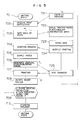
- Fig. 1 is a schematic block diagram of an image printer system including the above-described control unit 500, and also electrical connections of the constructive elements and external information processing apparatus connected to this control unit 500.
- the control unit 500 is arranged by a CPU 501 as a main control element.
- This control unit 500 further includes: a clock circuit 502 for generating a clock signal corresponding to an operation reference signal for this CPU 501; ROM 503 into which a detection signal is inputted by the CPU 501, and which produces a control signal so as to be outputted therefrom, and has stored therein a program and control base data and the like for performing a data processing operation in order to communicate with an external information processing apparatus 600 (will be described later); and RAM 504 for temporarily storing therein data under process by the CPU 501.
- the control unit 500 also includes: comparators 505 and 506 for binary-coding detection signals derived from two photo-sensors 410 and 420; an input port 507 for inputting the binary-coded detection signals outputted from the comparators 505 and 506 into the CPU 501; an output port 508 for outputting the control signals derived from the CPU 501; a laser controller 509 for controlling tuning ON/OFF the semiconductor laser diode 31 in response to the image signal in synchronism with the reference position signal outputted from the beam detector 38; and also a communication circuit 510 for communicating with the external information processing apparatus 600 under control of the CPU 501 so as to send/receive the data with the laser controller 509.
- the photo-sensor 410 is equipped with an LED 411 and a light receiving element 412, whereas the photo-sensor 420 is arranged by an LED 421 and a light receiving element 422.
- the output port 508 Under instruction from the CPU 501, the output port 508 outputs a signal for controlling a magnitude of an output voltage of a high-voltage power source 91 for generating a high voltage to be applied to the above-described belt charger 55; outputs another control signal for controlling a voltage control circuit 92 to control a potential of the suction auxiliary roller 56; and also outputs a further control signal for controlling a scanner controller 93 to control the rotation velocity of the scanner (drive motor) 33.
- the external information processing apparatus 600 is mainly arranged by a host CPU 601.
- This external information processing apparatus 600 is so designed that in accordance with a process function instruction inputted from the keyboard 603 via the keyboard control circuit 602 and also process data, the image information processing operation is executed so as to store this image data into a bit map memory 604, this image data is displayed on a CRT display unit 606 under control of the CRT controller 605, and the image data is outputted as video data to the communication circuit 510 of the control unit 500 under control of the printer controller 607.
- the CPU 501 employed at the control unit (500) is brought into a state for waiting for a print instruction signal and also controls the fixing apparatus 80 at a preselected temperature when a power supply is turned ON (a processing step 701).
- the CPU 601 When an operator manipulates the keyboard 603 at the external information processing apparatus 600 in order to instruct a printing operation of image information, the CPU 601 outputs the print instruction signal to the printer controller 607 (a processing step 721) and the printer controller 607 sends this print instruction signal to the communication circuit 510 employed at the control unit (500).
- the CPU 501 employed at the control unit (500) checks the detection signals derived from the photo-sensors 410 and 420 (a processing step 702) so as to confirm both the paper sizes and paper sorts of the paper 301 and 302 which have been set into the paper supply cassettes 110 and 120 loaded on the cassette loading holes 1a and 1b, and also to check operation states of other constructive elements, whereby confirmation can be established whether or not the printing operation is available, and furthermore transfers these check results as state signals via the communication circuit 510 to the external information processing apparatus (a processing step 703).
- this CPU 601 When the CPU 601 employed at the information processing apparatus receives this state signal via the printer controller 607, this CPU 601 checks this state signal in order to display on the CRT display unit, the paper sizes and sorts of the paper 301 and 302 which have been stored into the paper supply cassettes 110 and 120 loaded on the printer, and also whether or not the printing operation is available. Then, this CPU 601 requests a selection instructing input for the relevant paper supply cassette when the paper has been set whose size and sort are coincident with those of image information to be printed out, and requests the paper supply cassettes 110 and 120 for storing the relevant paper into the cassette loading holes 1a and 1b when the desired size and sort of the paper are not prepared (a processing step 722).
- the CPU 601 stores the image information to be printed out as the dot data in the bit map memory 604 (a processing step 723) and transfers a print starting instruction signal containing a paper supply cassette selecting signal via the printer controller 607 to the printer side when the image information storage is completed (a processing step 724).
- the CPU 501 employed at the printer side sets a Busy N at a low level, and controls the various drive power supplies so as to start the photoconductive-sensitive drum 10, charger 20, exposing apparatus 30, developing apparatus 40, transferring apparatus 50, cleaner 60, eraser 70 and fixing apparatus 80.
- the control data which has been stored in ROM 503 is read out in response to the paper supply cassette selecting signal in order to charge the transfer belt 54 at an optimum value with respect to the sort of used paper, and the output voltage from the high voltage power supply 91 is controlled.
- the voltage control circuit 92 is controlled so as to control the potential of the suction auxiliary roller 56.
- the toner image formed on the photoconductive-sensitive drum 10 is transferred to the paper 301 by receiving the effect of the electrons charged on the transfer belt 54.
- the transfer efficiency is sensitive also to the surface potential of the paper 301. When the surface potential of the paper 301 is increased, the transfer efficiency is also increased. However, if the surface potential becomes too high, discharge may happen to occur between the charged paper 301 and photoconductive-sensitive drum 10, which results in lowering of image quality.
- control data required for achieving the optimum belt charging voltage and also optimum surface potential in accordance with the sort of the used paper 301 has been previously stored into ROM 503, and thus the CPU 501 reads out this control data so as to optimize the controls of the above-described high voltage power supply 91 and voltage control circuit 92 (a processing step 704).
- one sheet of paper 301 (302) which have been stored into the paper supply cassette 110 (120) instructed by the paper supply cassette selecting signal is extracted and then supplied to the register roller 160 (a processing step 705).
- the CPU 501 Upon completion of the printing preparation, the CPU 501 generates a vertical synchronization signal at a timing of T1 (print starting timing signal in the paper supply direction), and transfers the vertical synchronization signal via the communication circuit 510 to the information processing-apparatus 600.
- the CPU 601 employed at the information processing apparatus 600 enters into a transmission preparation state for the image data (image signal) stored into the bit map memory 604.
- the deflection position of the laser beam becomes a starting reference position for exposure scanning, and the communication circuit 510 is controlled in order to transfer the horizontal synchronization signal obtained from the beam detector 38 to the information processing apparatus 600 (a processing step 706).
- the CPU 601 employed at the information processing apparatus Upon receipt of this horizontal synchronization signal, the CPU 601 employed at the information processing apparatus transmits the image signal scanned for one scanning period in synchronism with this horizontal synchronization signal (a processing step 725).
- the CPU 501 employed at the control unit (50) supplies this image signal to the laser controller 509 in order to control the communication circuit 510 enabling the laser diode 31 to be turned ON/OFF and enters into the scanning operation (a processing step 707).
- the electrostatic latent image formed by the above-described scanning operation is formed as a toner image by the developing apparatus 40.
- the resist roller 160 is rotated at T2 so as to restart the transportation of the paper 301 (302), and thus the toner image formed on the photoconductive-sensitive drum 10 is transferred on the paper 301.
- the toner image is fixed thereon and thereafter ejected on the paper eject tray 230 of the paper ejecting apparatus 200 (a processing step 708).
- Busy N of the CPU 501 becomes a high level while printing the image signal consisting of one page, and is brought into a condition for waiting for a printing instruction signal of a next page. Then, when confirmation is made that no printing instruction signal for the subsequent page is inputted within a predetermined time period (i.e., a time period until the printed paper has been ejected) (a processing step 709), the various drive motors are stopped (a processing step 710).
- a predetermined time period i.e., a time period until the printed paper has been ejected
- the CPU 601 employed at the side of the information processing apparatus 600 accomplishes the transmission of the image information on the previous page
- the image data on the next page is immediately stored in the bit map memory 604, and before the CPU 501 executes the stop processing operation, the CPU 601 generates the printing instruction signal for the next page and repeats the data processing operation for the printing operation.
- the printer can control the transfer conditions at the optimum states in response to the sorts of the paper 301 (302) used in the printer. Also, since the quick recognition can be achieved which sort of the paper has been set to the connected printer at the side of the external information processing apparatus, the printing image quality can be improved and simultaneously the easy operation can be achieved.
- Fig. 6 there is shown a modification of the image printer system according to the present invention, in which sort information among the sorts of the paper set in the above-described printer may be inputted by operating switches of an operation panel 94 employed on the upper portion of this printer.
- a back-up battery 511 is connected to this RAM 504 in order not to lose this data even when the power supply is turned OFF.
- the CPU 501 continuously monitors whether or not the paper supply cassettes 110 and 120 are loaded.
- the CPU 501 When the paper supply cassettes 110 and 120 are loaded or unloaded on this printer, the CPU 501 requests the display lamp employed in the operation panel 94 to be flickered in order that the sort information of the paper which has been stored into these cassettes is inputted into this operation panel 94. Then, when no sort information of the paper stored in the paper supply cassette is inputted, this stored paper is recognized as normal paper.
- the CPU 501 requests the sort information to be inputted under condition that only the paper size has been changed and the power source is turned ON.
- the printer may be constructed at reasonable cost.
- Figs. 7 and 8 represent another modification of the image printer system according to the present invention.
- this printer there is provided a pocket 116 on a side wall of the paper supply cassette 110, into which a bar code label 310 representative of a product name (sort) of paper stored into this paper supply cassette 110 is inserted.
- a bar code reader 95 for reading this bar code reader 95 for reading this bar code label 310 of the paper supply cassette 110 loaded on the cassette loading holes 1a and 1b is employed within the printer body 1.
- the bar code lable 310 may be obtained by either stripping, or cutting away a product name attached on wrapping paper 320 for paper.
- a bar code reader controller 512 is employed in the control unit 500, which transfers the paper sort information (product name) read by the bar code reader 95 to the CPU 501.
- ROM 503 there is stored control data on the belt charging voltage suitable for this paper and also the surface potential of the paper in accordance with this read paper name.
- the CPU 501 reads out this control data from ROM 503 based upon the paper name information read by the bar code reader 95, so as to control both the high-voltage power supply 91 and potential control circuit 92.
- the CPU 501 In case that no control data corresponding to the paper name information read by the bar code reader 95 has been stored into ROM 503, the CPU 501 requests the control data to be inputted by the operation panel. If no input is entered from the operation panel, the paper stored into the cassette is handled as normal paper.
- paper name information is transferred to the information processing apparatus so as to be displayed thereon.
- the sort of this paper can be intentionally set by the operator, there is no necessity to prepare a large number of paper supply cassettes in the image printing apparatus. Furthermore, since the set-paper-sort signal outputting means delivers to the external apparatus the paper sort signal corresponding to the paper which have been stored into all of the paper supply cassettes set in this image printer system, it is convenient in the external information processing apparatus which can previously recognize the usable paper set in this image printer system.
- the operating characteristic control of the transferring apparatus can be firmly performed in accordance with the used paper.
Claims (2)
- Bilddruckersystem, enthaltend:
ein externes Informationsverarbeitungsgerät (600) zur Erzeugung einer zu druckenden Bildinformation;
einen drehbar angetriebenen fotoleitend empfindlichen Körper (10);
ein Aufladungsgerät (20) zur einheitlichen Aufladung des fotoleitend empfindlichen Körpers;
ein Belichtungsgerät (30) zur Belichtung des einheitlich aufgeladenen fotoleitend empfindlichen Körpers als Reaktion auf ein Bildsignal, das von dem externen Informationsverarbeitungsgerät eingegeben wird, um so ein elektrostatisches latentes Bild zu erzeugen;
ein Entwicklungsgerät (40) zur Entwicklung des elektrostatischen latenten Bildes, das auf dem fotoleitend empfindlichen Körper gebildet wird, um ein sichtbares Bild zu erhalten;
ein Papiertransportgerät (100, 200), enthaltend eine Papierzufuhrkassette (110, 120) zum Extrahieren von Papier, auf das das sichtbare Bild, gebildet auf dem fotoleitend empfindlichen Körper, übertragen wird, aus der Kassette zwecks Transports;
ein Übertragungsgerät (50) zum Übertragen des sichtbaren Bildes, das auf dem fotoleitend empfindlichen Körper gebildet wird, auf das Papier; und
Einrichtungen (112, 114, 115, 410, 420) zur Erzeugung eines Papiersortensignals entsprechend der in der Papierzufuhrkassette gespeicherten Papiersorte;
Einrichtungen (507, 410) zur Ausgabe eines Einsatz-Papiersortensignals, um dieses Signal an das externe Informationsverarbeitungsgerät zu senden; und
einem Druckerkörper (1) mit einer Steuereinheit (501) zur Steuerung der Geräte, dadurch gekennzeichnet, daßa) das externe Informationsverarbeitungsgerät (600) aufweist:
eine Displayeinheit (605, 606) zum Display der Papierinformation des Papiers, das in der in den Druckerkörper eingesetzten Papierzufuhrkassette gespeichert ist, auf der Basis des Papiersortensignals, das von dem Druckerkörper (1) übertragen wird, und zur Anzeige der Papierinformation an die Bedienperson,
eine Eingabeeinrichtung (602, 603) zur Eingabe einer Instruktion, die zum Drucken der Bildinformation erforderlich ist, und
eine Einrichtung (601, 607) zur Erzeugung eines Papierzufuhrkassetten-Auswahlsignals zur Auswahl der Papierzufuhrkassette, die das zum Drucken der Bildinformation anwendbare Papier speichert, und zur Übertragung des Papierzufuhrkassetten-Auswahlsignals an den Druckerkörper (1), und daßb) der Druckerkörper (1) ausgerüstet ist mit
einer Mehrzahl von Kassetteneinführungsöffnungen (1A, 1B), in die Papierzufuhrkassetten abnehmbar eingesetzt sind, und
einer Mehrzahl von Papierzufuhrkassetten (110, 120), die mit Anzeigern (112, 114, 115) versehen sind, die repräsentativ für Größe und Sorte des gespeicherten Papiers sind und abnehmbar in die Kassetteneinführungsöffnungen eingesetzt sind,
wobei die Einrichtung zur Erzeugung von Papiersortensignalen (112, 114, 115, 410, 420) das Papiersortensignal erzeugt, das den Anzeigern jeder der eingesetzten Papierzufuhrkassetten entspricht,
und daß die Steuereinheit (501) versehen ist mit
einer Betriebscharakteristik-Steuerfunktion (704) zur Steuerung der Betriebscharakteristik des Übertragungsgerätes in Reaktion auf das in der ausgewählten Papierzufuhrkassette gespeicherten Papiers entsprechend dem Papierzufuhrkassetten-Auswahlsignal, das von dem externen Informationsverarbeitungsgerät übertragen wird, und
einer Papierzufuhr-Steuerfunktion (705) für Auswahl und Zufuhr der ausgewählten Papierzufuhrkassette. - Bilddrucker nach Anspruch 1, dadurch gekennzeichnet, daß die Anzeiger (112, 114, 115) die Größe, die Form und die Sorte des Papiers repräsentieren.
Applications Claiming Priority (2)
| Application Number | Priority Date | Filing Date | Title |
|---|---|---|---|
| JP265204/89 | 1989-10-13 | ||
| JP1265204A JP2880536B2 (ja) | 1989-10-13 | 1989-10-13 | 画像印刷装置 |
Publications (3)
| Publication Number | Publication Date |
|---|---|
| EP0422604A2 EP0422604A2 (de) | 1991-04-17 |
| EP0422604A3 EP0422604A3 (en) | 1992-01-02 |
| EP0422604B1 true EP0422604B1 (de) | 1994-06-08 |
Family
ID=17413981
Family Applications (1)
| Application Number | Title | Priority Date | Filing Date |
|---|---|---|---|
| EP19900119401 Expired - Lifetime EP0422604B1 (de) | 1989-10-13 | 1990-10-10 | Bild-Druckersystem |
Country Status (3)
| Country | Link |
|---|---|
| EP (1) | EP0422604B1 (de) |
| JP (1) | JP2880536B2 (de) |
| DE (1) | DE69009654T2 (de) |
Families Citing this family (5)
| Publication number | Priority date | Publication date | Assignee | Title |
|---|---|---|---|---|
| GB9119487D0 (en) * | 1991-09-11 | 1991-10-23 | Xerox Corp | Reprographic apparatus |
| DE4220003C2 (de) * | 1992-06-19 | 2001-11-22 | Meto International Gmbh | Thermodrucker |
| JP3368066B2 (ja) * | 1994-09-06 | 2003-01-20 | キヤノン株式会社 | 画像記録装置および画像記録方法 |
| JP3326997B2 (ja) * | 1994-10-17 | 2002-09-24 | 株式会社日立製作所 | 封筒給紙装置 |
| JP2007003966A (ja) * | 2005-06-27 | 2007-01-11 | Konica Minolta Business Technologies Inc | 画像形成装置及び画像形成方法 |
Family Cites Families (8)
| Publication number | Priority date | Publication date | Assignee | Title |
|---|---|---|---|---|
| US4583834A (en) * | 1977-09-16 | 1986-04-22 | Ricoh Company, Ltd. | Copying apparatus |
| JPS5817468A (ja) * | 1981-07-23 | 1983-02-01 | Canon Inc | 静電転写装置 |
| JPS60218974A (ja) * | 1984-04-16 | 1985-11-01 | Canon Inc | フアクシミリ装置 |
| US4780740A (en) * | 1985-04-02 | 1988-10-25 | Kentek Information Systems, Inc. | Paper feeding cassette for a printing apparatus |
| US4753543A (en) * | 1985-06-24 | 1988-06-28 | Ricoh Company, Ltd. | Electrostatic printing apparatus with heated adjustable pressure toner fixing rolls |
| JPS63160938A (ja) * | 1986-12-24 | 1988-07-04 | Minolta Camera Co Ltd | 画像形成装置 |
| JPH0199075A (ja) * | 1987-10-12 | 1989-04-17 | Tokyo Electric Co Ltd | 乾式電子写真装置 |
| JPH01152482A (ja) * | 1987-12-09 | 1989-06-14 | Tokyo Electric Co Ltd | 乾式電子写真装置 |
-
1989
- 1989-10-13 JP JP1265204A patent/JP2880536B2/ja not_active Expired - Lifetime
-
1990
- 1990-10-10 EP EP19900119401 patent/EP0422604B1/de not_active Expired - Lifetime
- 1990-10-10 DE DE1990609654 patent/DE69009654T2/de not_active Expired - Fee Related
Also Published As
| Publication number | Publication date |
|---|---|
| EP0422604A3 (en) | 1992-01-02 |
| JP2880536B2 (ja) | 1999-04-12 |
| DE69009654T2 (de) | 1995-01-26 |
| EP0422604A2 (de) | 1991-04-17 |
| JPH03127077A (ja) | 1991-05-30 |
| DE69009654D1 (de) | 1994-07-14 |
Similar Documents
| Publication | Publication Date | Title |
|---|---|---|
| US5742327A (en) | Recording apparatus | |
| US6021284A (en) | Image forming apparatus, apparatus for supplying image data to image forming apparatus, and method of interfacing two apparatuses | |
| US6785478B2 (en) | Image formation apparatus and method for controlling the feed of a recording sheet prior to a print command | |
| US4944031A (en) | Operational condition setting device for an office machine | |
| JP2892085B2 (ja) | 給送制御装置 | |
| JPH0199075A (ja) | 乾式電子写真装置 | |
| US6099181A (en) | Printing control apparatus, printing method with the printing control apparatus, and storage medium storing a computer readable program | |
| EP0422604B1 (de) | Bild-Druckersystem | |
| US5124727A (en) | Page printer capable of efficiently printing data on paper sheets having different sizes | |
| EP0227243B1 (de) | Bilderzeugungsgerät | |
| JP2703966B2 (ja) | 画像形成装置 | |
| US5790767A (en) | Information outputting apparatus | |
| JPH0730704A (ja) | 画像形成装置 | |
| US4952981A (en) | Toner image printing apparatus | |
| JPH02182631A (ja) | 画像形成装置 | |
| JP2763120B2 (ja) | 画像形成装置 | |
| JP2728882B2 (ja) | 事務機器の動作条件設定装置 | |
| JP2706084B2 (ja) | 事務機器の動作条件設定装置 | |
| JP3136373B2 (ja) | パーソナル収納容器および記録装置 | |
| JPH05193234A (ja) | 画像形成装置 | |
| JP2788759B2 (ja) | ページプリンタ | |
| JPH03259325A (ja) | データ伝送システム | |
| JPH02182634A (ja) | 画像形成装置 | |
| JPS61188346A (ja) | 記録装置 | |
| JPH03227682A (ja) | 画像形成装置 |
Legal Events
| Date | Code | Title | Description |
|---|---|---|---|
| PUAI | Public reference made under article 153(3) epc to a published international application that has entered the european phase |
Free format text: ORIGINAL CODE: 0009012 |
|
| 17P | Request for examination filed |
Effective date: 19901010 |
|
| AK | Designated contracting states |
Kind code of ref document: A2 Designated state(s): CH DE FR GB IT LI NL SE |
|
| PUAL | Search report despatched |
Free format text: ORIGINAL CODE: 0009013 |
|
| AK | Designated contracting states |
Kind code of ref document: A3 Designated state(s): CH DE FR GB IT LI NL SE |
|
| 17Q | First examination report despatched |
Effective date: 19930329 |
|
| GRAA | (expected) grant |
Free format text: ORIGINAL CODE: 0009210 |
|
| AK | Designated contracting states |
Kind code of ref document: B1 Designated state(s): DE FR GB |
|
| REF | Corresponds to: |
Ref document number: 69009654 Country of ref document: DE Date of ref document: 19940714 |
|
| ET | Fr: translation filed | ||
| PLBE | No opposition filed within time limit |
Free format text: ORIGINAL CODE: 0009261 |
|
| STAA | Information on the status of an ep patent application or granted ep patent |
Free format text: STATUS: NO OPPOSITION FILED WITHIN TIME LIMIT |
|
| 26N | No opposition filed | ||
| PGFP | Annual fee paid to national office [announced via postgrant information from national office to epo] |
Ref country code: FR Payment date: 19970917 Year of fee payment: 8 |
|
| PGFP | Annual fee paid to national office [announced via postgrant information from national office to epo] |
Ref country code: GB Payment date: 19970925 Year of fee payment: 8 |
|
| PG25 | Lapsed in a contracting state [announced via postgrant information from national office to epo] |
Ref country code: GB Free format text: LAPSE BECAUSE OF NON-PAYMENT OF DUE FEES Effective date: 19981010 |
|
| GBPC | Gb: european patent ceased through non-payment of renewal fee |
Effective date: 19981010 |
|
| PG25 | Lapsed in a contracting state [announced via postgrant information from national office to epo] |
Ref country code: FR Free format text: LAPSE BECAUSE OF NON-PAYMENT OF DUE FEES Effective date: 19990630 |
|
| REG | Reference to a national code |
Ref country code: FR Ref legal event code: ST |
|
| PGFP | Annual fee paid to national office [announced via postgrant information from national office to epo] |
Ref country code: DE Payment date: 20061005 Year of fee payment: 17 |
|
| PG25 | Lapsed in a contracting state [announced via postgrant information from national office to epo] |
Ref country code: DE Free format text: LAPSE BECAUSE OF NON-PAYMENT OF DUE FEES Effective date: 20080501 |