EP0420949B1 - Dispositif de freinage a regulation du glissement, notamment pour vehicules a moteur - Google Patents
Dispositif de freinage a regulation du glissement, notamment pour vehicules a moteur Download PDFInfo
- Publication number
- EP0420949B1 EP0420949B1 EP90903168A EP90903168A EP0420949B1 EP 0420949 B1 EP0420949 B1 EP 0420949B1 EP 90903168 A EP90903168 A EP 90903168A EP 90903168 A EP90903168 A EP 90903168A EP 0420949 B1 EP0420949 B1 EP 0420949B1
- Authority
- EP
- European Patent Office
- Prior art keywords
- pressure
- slip
- brake system
- pressure fluid
- controlled brake
- Prior art date
- Legal status (The legal status is an assumption and is not a legal conclusion. Google has not performed a legal analysis and makes no representation as to the accuracy of the status listed.)
- Expired - Lifetime
Links
Images

Classifications
-
- B—PERFORMING OPERATIONS; TRANSPORTING
- B60—VEHICLES IN GENERAL
- B60T—VEHICLE BRAKE CONTROL SYSTEMS OR PARTS THEREOF; BRAKE CONTROL SYSTEMS OR PARTS THEREOF, IN GENERAL; ARRANGEMENT OF BRAKING ELEMENTS ON VEHICLES IN GENERAL; PORTABLE DEVICES FOR PREVENTING UNWANTED MOVEMENT OF VEHICLES; VEHICLE MODIFICATIONS TO FACILITATE COOLING OF BRAKES
- B60T8/00—Arrangements for adjusting wheel-braking force to meet varying vehicular or ground-surface conditions, e.g. limiting or varying distribution of braking force
- B60T8/32—Arrangements for adjusting wheel-braking force to meet varying vehicular or ground-surface conditions, e.g. limiting or varying distribution of braking force responsive to a speed condition, e.g. acceleration or deceleration
- B60T8/34—Arrangements for adjusting wheel-braking force to meet varying vehicular or ground-surface conditions, e.g. limiting or varying distribution of braking force responsive to a speed condition, e.g. acceleration or deceleration having a fluid pressure regulator responsive to a speed condition
- B60T8/36—Arrangements for adjusting wheel-braking force to meet varying vehicular or ground-surface conditions, e.g. limiting or varying distribution of braking force responsive to a speed condition, e.g. acceleration or deceleration having a fluid pressure regulator responsive to a speed condition including a pilot valve responding to an electromagnetic force
- B60T8/3615—Electromagnetic valves specially adapted for anti-lock brake and traction control systems
- B60T8/3675—Electromagnetic valves specially adapted for anti-lock brake and traction control systems integrated in modulator units
-
- B—PERFORMING OPERATIONS; TRANSPORTING
- B60—VEHICLES IN GENERAL
- B60T—VEHICLE BRAKE CONTROL SYSTEMS OR PARTS THEREOF; BRAKE CONTROL SYSTEMS OR PARTS THEREOF, IN GENERAL; ARRANGEMENT OF BRAKING ELEMENTS ON VEHICLES IN GENERAL; PORTABLE DEVICES FOR PREVENTING UNWANTED MOVEMENT OF VEHICLES; VEHICLE MODIFICATIONS TO FACILITATE COOLING OF BRAKES
- B60T8/00—Arrangements for adjusting wheel-braking force to meet varying vehicular or ground-surface conditions, e.g. limiting or varying distribution of braking force
- B60T8/32—Arrangements for adjusting wheel-braking force to meet varying vehicular or ground-surface conditions, e.g. limiting or varying distribution of braking force responsive to a speed condition, e.g. acceleration or deceleration
- B60T8/34—Arrangements for adjusting wheel-braking force to meet varying vehicular or ground-surface conditions, e.g. limiting or varying distribution of braking force responsive to a speed condition, e.g. acceleration or deceleration having a fluid pressure regulator responsive to a speed condition
- B60T8/40—Arrangements for adjusting wheel-braking force to meet varying vehicular or ground-surface conditions, e.g. limiting or varying distribution of braking force responsive to a speed condition, e.g. acceleration or deceleration having a fluid pressure regulator responsive to a speed condition comprising an additional fluid circuit including fluid pressurising means for modifying the pressure of the braking fluid, e.g. including wheel driven pumps for detecting a speed condition, or pumps which are controlled by means independent of the braking system
- B60T8/4068—Arrangements for adjusting wheel-braking force to meet varying vehicular or ground-surface conditions, e.g. limiting or varying distribution of braking force responsive to a speed condition, e.g. acceleration or deceleration having a fluid pressure regulator responsive to a speed condition comprising an additional fluid circuit including fluid pressurising means for modifying the pressure of the braking fluid, e.g. including wheel driven pumps for detecting a speed condition, or pumps which are controlled by means independent of the braking system the additional fluid circuit comprising means for attenuating pressure pulsations
-
- B—PERFORMING OPERATIONS; TRANSPORTING
- B60—VEHICLES IN GENERAL
- B60T—VEHICLE BRAKE CONTROL SYSTEMS OR PARTS THEREOF; BRAKE CONTROL SYSTEMS OR PARTS THEREOF, IN GENERAL; ARRANGEMENT OF BRAKING ELEMENTS ON VEHICLES IN GENERAL; PORTABLE DEVICES FOR PREVENTING UNWANTED MOVEMENT OF VEHICLES; VEHICLE MODIFICATIONS TO FACILITATE COOLING OF BRAKES
- B60T8/00—Arrangements for adjusting wheel-braking force to meet varying vehicular or ground-surface conditions, e.g. limiting or varying distribution of braking force
- B60T8/32—Arrangements for adjusting wheel-braking force to meet varying vehicular or ground-surface conditions, e.g. limiting or varying distribution of braking force responsive to a speed condition, e.g. acceleration or deceleration
- B60T8/34—Arrangements for adjusting wheel-braking force to meet varying vehicular or ground-surface conditions, e.g. limiting or varying distribution of braking force responsive to a speed condition, e.g. acceleration or deceleration having a fluid pressure regulator responsive to a speed condition
- B60T8/42—Arrangements for adjusting wheel-braking force to meet varying vehicular or ground-surface conditions, e.g. limiting or varying distribution of braking force responsive to a speed condition, e.g. acceleration or deceleration having a fluid pressure regulator responsive to a speed condition having expanding chambers for controlling pressure, i.e. closed systems
-
- B—PERFORMING OPERATIONS; TRANSPORTING
- B60—VEHICLES IN GENERAL
- B60T—VEHICLE BRAKE CONTROL SYSTEMS OR PARTS THEREOF; BRAKE CONTROL SYSTEMS OR PARTS THEREOF, IN GENERAL; ARRANGEMENT OF BRAKING ELEMENTS ON VEHICLES IN GENERAL; PORTABLE DEVICES FOR PREVENTING UNWANTED MOVEMENT OF VEHICLES; VEHICLE MODIFICATIONS TO FACILITATE COOLING OF BRAKES
- B60T8/00—Arrangements for adjusting wheel-braking force to meet varying vehicular or ground-surface conditions, e.g. limiting or varying distribution of braking force
- B60T8/32—Arrangements for adjusting wheel-braking force to meet varying vehicular or ground-surface conditions, e.g. limiting or varying distribution of braking force responsive to a speed condition, e.g. acceleration or deceleration
- B60T8/34—Arrangements for adjusting wheel-braking force to meet varying vehicular or ground-surface conditions, e.g. limiting or varying distribution of braking force responsive to a speed condition, e.g. acceleration or deceleration having a fluid pressure regulator responsive to a speed condition
- B60T8/44—Arrangements for adjusting wheel-braking force to meet varying vehicular or ground-surface conditions, e.g. limiting or varying distribution of braking force responsive to a speed condition, e.g. acceleration or deceleration having a fluid pressure regulator responsive to a speed condition co-operating with a power-assist booster means associated with a master cylinder for controlling the release and reapplication of brake pressure through an interaction with the power assist device, i.e. open systems
- B60T8/445—Arrangements for adjusting wheel-braking force to meet varying vehicular or ground-surface conditions, e.g. limiting or varying distribution of braking force responsive to a speed condition, e.g. acceleration or deceleration having a fluid pressure regulator responsive to a speed condition co-operating with a power-assist booster means associated with a master cylinder for controlling the release and reapplication of brake pressure through an interaction with the power assist device, i.e. open systems replenishing the released brake fluid volume into the brake piping
-
- F—MECHANICAL ENGINEERING; LIGHTING; HEATING; WEAPONS; BLASTING
- F16—ENGINEERING ELEMENTS AND UNITS; GENERAL MEASURES FOR PRODUCING AND MAINTAINING EFFECTIVE FUNCTIONING OF MACHINES OR INSTALLATIONS; THERMAL INSULATION IN GENERAL
- F16L—PIPES; JOINTS OR FITTINGS FOR PIPES; SUPPORTS FOR PIPES, CABLES OR PROTECTIVE TUBING; MEANS FOR THERMAL INSULATION IN GENERAL
- F16L55/00—Devices or appurtenances for use in, or in connection with, pipes or pipe systems
- F16L55/02—Energy absorbers; Noise absorbers
- F16L55/027—Throttle passages
-
- G—PHYSICS
- G01—MEASURING; TESTING
- G01L—MEASURING FORCE, STRESS, TORQUE, WORK, MECHANICAL POWER, MECHANICAL EFFICIENCY, OR FLUID PRESSURE
- G01L19/00—Details of, or accessories for, apparatus for measuring steady or quasi-steady pressure of a fluent medium insofar as such details or accessories are not special to particular types of pressure gauges
- G01L19/06—Means for preventing overload or deleterious influence of the measured medium on the measuring device or vice versa
- G01L19/0609—Pressure pulsation damping arrangements
-
- Y—GENERAL TAGGING OF NEW TECHNOLOGICAL DEVELOPMENTS; GENERAL TAGGING OF CROSS-SECTIONAL TECHNOLOGIES SPANNING OVER SEVERAL SECTIONS OF THE IPC; TECHNICAL SUBJECTS COVERED BY FORMER USPC CROSS-REFERENCE ART COLLECTIONS [XRACs] AND DIGESTS
- Y10—TECHNICAL SUBJECTS COVERED BY FORMER USPC
- Y10S—TECHNICAL SUBJECTS COVERED BY FORMER USPC CROSS-REFERENCE ART COLLECTIONS [XRACs] AND DIGESTS
- Y10S303/00—Fluid-pressure and analogous brake systems
- Y10S303/90—ABS throttle control
Definitions
- the invention relates to a brake system with slip control according to the preamble of claim 1.
- DE OS 35 05 410 already discloses a slip-controlled brake system which, as a brake pressure transmitter, has a master cylinder with an upstream hydraulic brake booster.
- the auxiliary pressure supply system contains a hydraulic pump which, in the case of a slip-controlled braking process after passing check valves connected in series in the pressure medium circuit, introduces an auxiliary pressure proportional to the force of the foot into the wheel brakes after opening the inlet valves which can be electromagnetically excited by control electronics.
- This pressure which is modulated by the dynamic pump frequency and the switching frequency, is transmitted to the master cylinder via the fluid and via the vibratory line system, so that, depending on the switching frequency of the intake and exhaust valves, all mass-related parts associated with the brake system, which consequently constitute an oscillation structure , taking into account the specific natural vibration number tend to build up resonance vibrations.
- a noise level which is occasionally perceived as disturbing is to be assessed as disadvantageous for the known brake system.
- a slip-controlled brake system with the features according to the preamble of the claimed subject matter is already known, which has an additional metallic and pressure-resistant damper chamber downstream of the pressure vibration generators such as the pump and control valve. This is intended to dampen the noise caused by vibrations caused by the pump or the control valves.
- the damper chamber is metallic and consequently also relatively pressure-resistant, pressure waves with different intensities can only be adapted partially and thus in a narrow frequency range to the expected sound field of the pressure vibration generator by appropriate geometric tuning of the damper chamber.
- the relatively high speed of sound propagation and the risk of resonance vibrations occurring when using metallic pressure chambers are to be regarded as disadvantageous in this context.
- the document US-A-3,331,398 describes a special embodiment for designing a pressure pulsation damper with defined deformation properties.
- This has a plurality of energy storage elements which are elastically deformable in a rigid housing and are designed as a ball and are arranged in a hydraulic branch of a pressure medium line. If required, the housing can be unscrewed from the line connection and, depending on the size of the housing, supplemented by further elastomeric energy storage elements which are arranged in series in the housing. Pressure pulsations that occur are then converted into deformation energy.
- the arrangement described above can dampen the pressure pulsations present directly at the line connection. However, an arrangement for the immediate damping of pulsations at the causal noise source does not emerge, so that the arrangement described can only have a limited noise-reducing effect.
- the invention is therefore based on the object of improving a slip-controlled hydraulic brake system in such a way that the previously described pressure pulsation which is acoustically perceptible by unsteady flow processes is reduced, while at the same time a cost-minimized modification of the brake system is possible while maintaining the almost conventional device structure.
- the energy storage element to be produced from heterogeneous materials, so that the degree of deformation depending on the hydraulic pressurization can be determined by the combination of different material properties. This allows For example, realize a degressive pressure increase so that the volume of the hydraulic circuit remains as low as possible during the uncontrolled normal braking.
- the desired property of the energy storage element can be realized in a simple, inexpensive manner, with sufficient rigidity in the overall composite of the body being ensured by enclosing the core by means of a fiber-reinforced shell.
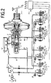
- the brake system consists essentially of a tandem master cylinder 2 and an upstream vacuum booster 3, the hydraulic unit, or the brake pressure sensor 1.
- the pedal force exerted on a brake pedal 5 is in a known manner via a push rod 4 F to the vacuum booster 3 and assisted by this to the working pistons 6 and 7 of the tandem master cylinder 2.
- the two brake circuits I and II are via the elastomeric pressure medium connection 27 according to the invention, which consists of two high-pressure hoses, which are arranged for each brake circuit I, II, with orifice bodies 51 integrated therein, and the electromagnetically operable inlet valves 24, 25, which are switched to passage in the basic position or 29, 30 connected to the wheel brakes 31, 32, 33, 34.
- the wheel brakes 31, 32 and 33, 34 connected in parallel are assigned to the diagonals.
- the wheel brakes 31, 32 33, 34 are connected to electromagnetically actuated, in the basic position blocked outlet valves 22, 23 and 35, 36, which on the one hand with a hydraulic return line 37 with the pressure expansion tank 20 and on the other hand via the suction line 61 with the suction sides of the by means of a drive motor "M” provided pumps 22, 26 in connection.
- the electrical ground connections "m” are also indicated symbolically.
- a monitoring circuit 40 is provided, with which the operation of the motor "M” can be checked.
- the vehicle wheels are equipped with inductive sensors S1 to S4, which interact with a toothed disc that rotates synchronously with the wheel rotation and generate electrical signals that determine the wheel rotation behavior, i.e. show the change in wheel speed.
- control electronics 28 which generate brake pressure control signals with which the inlet and outlet valves 22, 23, 24, 25 and 29, 30, 35, 36 temporarily switch over upon detection of a tendency to block and thereby the brake pressure kept constant, dismantled and opened again at the appropriate time.
- the actuating magnets of the intake and exhaust valves are actuated via the outputs A1 to A4, and the electrical connecting lines between the connections A1 to A4 and the windings of the valves 22, 23, 24, 25 and 29, 30, 35, 36 (not shown) are produced .
- Fig. 2 shows schematically an identical to Fig. 1 hydraulic circuit, so that analog to Fig. 1, the two brake circuits I and II of the master cylinder 2 via electromagnetically actuated, in the basic position switched to passage valves 24, 25 and 29, 30 with the wheel brakes 31, 32, 33, 34 are connected, the vibration-damping, elastomeric energy storage elements 27 according to the invention, in deviation from FIG. 1, in each case in the immediate vicinity of the inlet and inlet valves 24, 25, 29, 30, 22, 23 35, 36 are placed in the shunt of the branch lines 47, 48, 49, 50.
- the slip control starts:
- the drive motor "M" of the pump 21, 26 switches on, with a dynamically pulsating in the two inflow lines Builds up pressure that is proportional to the pump rotation frequency acts as the excitation frequency via the check valves 38, 39 and branch lines 47, 48 and 49, 50 on the inlet valves 24, 25 and 29, 30 and on the pressure chambers 8, 9 of the master cylinder 2.
- the pulsating and thus unsteady pressure source first experiences a damping effect due to the volume expansion of the elastomeric hose piece, which leads to a reduction in the amplitude, whereby while tuning the diaphragm body 51 to the excitation frequency proportional to the pump rotation frequency, an unsteady, phase-shifted carrier wave remains in the conversion of the pressure energy into kinetic energy. The consequently changed speed of sound propagation prevents the occurrence of interference, so that the sum of the amplitudes of the individual waves tends to remain small.
- At least the elastomeric pressure medium connection must be coordinated with the diaphragm body in such a way that the lowest possible sound pressure level can be used as a basis for the hearing-sensitive frequency range from 16 to 20,000 Hz.
- a signal from the control electronics 28 leads to the switchover of the electromagnetically actuated inlet valves 24, 25 and 29, 30 and thus to the shutoff of the brake circuits I and II or the branch lines 47 to 50, whereby additional interference frequencies depending on the propagation speed of the pressure waves can contribute to noise generation.
- the further displacement of the master cylinder pistons 6, 7 in the direction of the pedal force F, as well as an emptying of the pressure chambers 8, 9 is prevented since the pressure medium from the pumps 21, 26 tries to flow the open check valves 38, 39 and the main brake lines 62, 63 into the pressure chambers 8, 9 in a pulsed manner in order to push the pistons 6, 7 back into their starting position.
- the brake pressure curve in the wheel brakes 31 to 34 is determined by the inlet and outlet valves 24, 25, 29, 30 and 22, 23, 35, 36, to which further slip-controlled brake pressure control signals are fed via lines A1 to A4.
- the inlet valves 24, 25 and 29, 30 are still secured by check valves connected in parallel.
- these check valves enable the brake pressure control to be terminated or the wheel brakes to be released, since with inlet valves 24, 25 and 29, 30 and outlet valves 21, 23 and 35, 36 still closed, a small amount of pressure medium from the wheel brakes 31 to 34 can flow back into the pressure chambers 8, 9 when the pistons 6, 7 of the master cylinder 2 are pushed back into the starting position and the central control valves 10, 11 are in the open position.
- the pedal force F is supported by the negative pressure in the amplifier 3 when the brake is actuated the master cylinder pistons 6, 7 transmit.
- the central control valves 10, 11 close, so that brake pressure can now build up in the pressure chambers 8, 9 and thus in the brake circuits I and II, which via the valves 24, 25 and 29, 30 to the wheel brakes 31, 32 and 33 , 34 arrives.
- the slip control starts in a known manner.
- the drive motor M of the pumps 21, 26 is activated, a dynamic but pulsating pressure building up in the two inflow lines, which pressure via the check valves 38, 39 and the branch lines 47, 48 or 49, 50 to the inlet valves 25, 26 or . 29, 30 acts.
- the pulsating and thus unsteady pressure wave experiences a damping effect due to the volume expansion.
- An elliptically shaped body, the structure core 42 of which has great elasticity, is preferably suitable as the energy storage element 27, the envelope 43 surrounding the structure core 42 made of a material of high density and has rigidity with elastic deformation properties, so that an energy storage element 27 of defined deformation can be produced by coordinating the structural core 42 and the casing 43, so that, for example, a degressive characteristic curve can be impressed on the transient pressure curve.
- deformation of the energy storage element 27 is initially ruled out, which advantageously avoids additional volume absorption by the hydraulic system.
- a desired, defined deformation of the energy storage element 27 for the purpose of noise reduction occurs only at high pressures.
- a disadvantageous effect of the variable volume increase at high pressures can be classified as negligible.
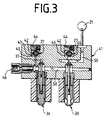
- Fig. 3 shows the structural arrangement of two elastomeric energy storage elements 27 in the branch lines 47 to 50 connected to the pumps 21, 26, wherein in the sectional drawing of the inlet and outlet valves 22 to 25, 29, 30, 35 combined to form a valve block 41 , 36 only the inlet valve 30 and outlet valve 36 known from FIG. 2 can be seen as an example. Adjacent to the illustrated branch line 50, the energy storage elements 27 according to the invention are assigned to the inlet valve 30 and the outlet valve 36 on the pressure side.
- the energy storage elements 27 are shaped as spherical bodies, the soft structural core 42 being surrounded by a sheath 43 of high material density and rigidity , so that when the branch lines 50 are pressurized depending on
- the energy storage element 27, which is hydraulically arranged in a chamber 45 closed by means of a screw connection 44, ensures a defined deformation and volume absorption of the hydraulic system before, for example, a backflow via the return line 37 to the reservoir 20 or inflow to the illustrated wheel connection 46 he follows.
- the damping elements arranged in front of the outlet valves can also be matched in such a way that the pressure build-up and reduction gradients are linearized over a large pressure range.
- the hydraulic pressure In vehicles with a high blocking pressure level (> 100 bar), the hydraulic pressure remains constant over a wide pressure range during the pressure increase and decrease per valve pulse.
Landscapes
- Engineering & Computer Science (AREA)
- Physics & Mathematics (AREA)
- Fluid Mechanics (AREA)
- Mechanical Engineering (AREA)
- Transportation (AREA)
- Electromagnetism (AREA)
- General Engineering & Computer Science (AREA)
- General Physics & Mathematics (AREA)
- Regulating Braking Force (AREA)
Abstract
Claims (13)
- Système de freinage à régulation du glissement, notamment pour véhicule automobile, comprenant un générateur de pression de freinage (1), qui est actionné au moyen d'une pédale et est assisté par une force auxiliaire et qui comprend un maître-cylindre (2) auquel les freins de roues sont raccordés par des conduites principales de freinage (62, 63), constitué de pompes hydrauliques de pression auxiliaire (21, 26), de capteurs de roues (S1, S2, S3, S4) et de circuits électroniques servant à déterminer le comportement des roues en rotation et à produire des signaux électriques de commande de pression de freinage au moyen desquels peuvent être commandées, en vue de la régulation du glissement, des valves d'entrée d'agent de pression et valves de sortie d'agent de pression (24, 25, 29, 30 et 22, 23, 35, 36) à actionnement électromagnétique et insérées dans les conduites d'agent de pression, tandis que des amortisseurs de pulsations de pression (27) possédant des propriétés déterminées de déformation et/ou des longueurs déterminées de passage d'écoulement sont disposés dans les conduites d'agent de pression entre le maître-cylindre (2) et les valves d'entrée et valves de sortie (24, 25, 29, 30 et 22, 23, 35, 36), caractérisé en ce que des liaisons d'agent de pression (27), présentant des propriétés analogues à celles des élastomères, amortissant les oscillations, servant d'amortisseurs de pulsations de pression et possédant une dilatation volumique déterminée et une longueur déterminée de passage d'écoulement, sont disposés, à proximité directe du maître-cylindre (2), dans les conduites principales de freinage (62, 63) réunissant le maître-cylindre (2) et les pompes hydrauliques de pression auxiliaire (21, 26) et en ce que les liaisons d'agent de pression (27), présentant des propriétés analogues à celles des élastomères, qui amortissent les oscillations, comprennent des corps à diaphragme (51), de sorte qu'une onde de pression ayant une fréquence déterminée d'excitation est soumise à un amortissement dans ces liaisons d'agent de pression (27) présentant des propriétés analogues à celles des élastomères.
- Système de freinage à régulation du glissement suivant la revendication 1, caractérisé en ce que la dilatation volumique de la liaison d'agent de pression (27) présentant des propriétés analogues à celles des élastomères n'est pas supérieure à 3 mm³ par bar d'unité de pression.
- Système de freinage à régulation du glissement suivant l'une des revendications précédentes, caractérisé en ce que le volume d'accumulation de la liaison d'agent de pression (27) présentant des propriétés analogues à celles des élastomères n'est pas supérieur à 1 cm³ par mètre de longueur de tuyau souple.
- Système de freinage à régulation du glissement suivant l'une des revendications précédentes, caractérisé en ce que la longueur de la liaison d'agent de pression (27) présentant des propriétés analogues à celles des élastomères n'est pas supérieure à 1,5 cm.
- Système de freinage à régulation du glissement, notamment pour véhicule automobile, comprenant un générateur de pression de freinage (1), qui est actionné au moyen d'une pédale et est assisté par une force auxiliaire et qui comprend un maître-cylindre (2) auquel les freins de roues sont raccordés par des conduites principales de freinage (62, 63), constitué de pompes hydrauliques de pression auxiliaire (21, 26), de capteurs de roues (S1, S2, S3, S4) et de circuits électroniques servant à déterminer le comportement des roues en rotation et à produire des signaux électriques de commande de pression de freinage au moyen desquels peuvent être commandées, en vue de la régulation du glissement, des valves d'entrée d'agent de pression et valves de sortie d'agent de pression (24, 25, 29, 30 et 22, 23, 35, 36) à actionnement électromagnétique et insérées dans les conduites d'agent de pression, tandis que des amortisseurs de pulsations de pression (27) possédant des propriétés déterminées de déformation et/ou des longueurs déterminées de passage d'écoulement sont disposés dans les conduites d'agent de pression entre le maître-cylindre (2) et les valves d'entrée et valves de sortie (24, 25, 29, 30 et 22, 23, 35, 36), caractérisé en ce qu'au moins un élément d'accumulation d'énergie (27) présentant des propriétés analogues à celles des élastomères, qui amortit les oscillations et possède des propriétés déterminées de déformation en vue d'influer sur l'augmentation variable de volume pouvant être acceptée dans les conduites d'agent de pression, est disposé, en tant qu'amortisseur de pulsations de pression et au voisinage direct des valves soumises hydrauliquement à une action du côté de la pression, entre les valves d'entrée d'agent de pression (24, 25, 29, 30), et les valves de sortie d'agent de pression (22, 23, 35, 36), et les pompes hydrauliques de pression auxiliaire (21,, 26).
- Système de freinage à régulation du glissement suivant la revendication 5, caractérisé en ce que l'augmentation variable de volume pouvant être acceptée par l'élément d'accumulation d'énergie (27) est au maximum égale à 2 mm³ par bar de pression.
- Système de freinage à régulation du glissement suivant l'une des revendications 5 et 6, caractérisé en ce que l'élément d'accumulation d'énergie (27) a de préférence une forme elliptique et est pourvu d'un noyau de structure hétérogène ayant une densité de structure et une dureté assez faibles, mais une élasticité assez élevée.
- Système de freinage à régulation du glissement suivant la revendication 7, caractérisé en ce que le noyau de structure (42) est entouré d'une enveloppe (43) dont la matière possède, comme propriétés, une densité et une rigidité élevées et un taux de déformation élastique élevé.
- Système de freinage à régulation du glissement suivant l'une des revendications précédentes, caractérisé en ce que l'élément d'accumulation d'énergie (27) comporte des matières composites, de préférence des matières composites contenant des fibres.
- Système de freinage à régulation du glissement suivant la revendication 7, caractérisé en ce que le noyau de structure (42) est constitué de matières organiques métalliques, notamment de matières plastiques élastomères à base de caoutchouc naturel.
- Système de freinage à régulation du glissement suivant la revendication 5, caractérisé en ce que l'élément d'accumulation d'énergie (27) est disposé en dérivation par rapport aux branches de conduite (47, 48, 49, 50) soumises à une pression.
- Système de freinage à régulation du glissement suivant la revendication 11, caractérisé en ce que l'agencement de l'élément d'accumulation d'énergie (27) est réalisé dans une chambre (45), la dimension de largeur libre de la chambre (45) étant égale à la dimension extérieure de l'élément d'accumulation d'énergie (27) qui est soumise à une pression.
- Système de freinage à régulation du glissement suivant l'une des revendications précédentes, caractérisé en ce que le taux de déformation de l'élément d'accumulation d'énergie (27) provoque une augmentation de pression, présentant une certaine dégressivité, ainsi qu'une diminution de pression, présentant une certaine progressivité, dans les freins de roues (31 ,32, 33, 34).
Applications Claiming Priority (4)
| Application Number | Priority Date | Filing Date | Title |
|---|---|---|---|
| DE19893913352 DE3913352A1 (de) | 1989-04-22 | 1989-04-22 | Schlupfgeregelte hydraulische bremsanlage, insbesondere fuer kraftfahrzeuge |
| DE3913352 | 1989-04-22 | ||
| DE19893914953 DE3914953A1 (de) | 1989-05-06 | 1989-05-06 | Schlupfgeregelte bremsanlage, insbesondere fuer kraftfahrzeuge |
| DE3914953 | 1989-05-06 |
Publications (2)
| Publication Number | Publication Date |
|---|---|
| EP0420949A1 EP0420949A1 (fr) | 1991-04-10 |
| EP0420949B1 true EP0420949B1 (fr) | 1994-01-12 |
Family
ID=25880204
Family Applications (1)
| Application Number | Title | Priority Date | Filing Date |
|---|---|---|---|
| EP90903168A Expired - Lifetime EP0420949B1 (fr) | 1989-04-22 | 1990-02-17 | Dispositif de freinage a regulation du glissement, notamment pour vehicules a moteur |
Country Status (5)
| Country | Link |
|---|---|
| US (2) | US5209554A (fr) |
| EP (1) | EP0420949B1 (fr) |
| JP (1) | JPH03505716A (fr) |
| DE (1) | DE59004211D1 (fr) |
| WO (1) | WO1990012713A1 (fr) |
Families Citing this family (27)
| Publication number | Priority date | Publication date | Assignee | Title |
|---|---|---|---|---|
| EP0420949B1 (fr) * | 1989-04-22 | 1994-01-12 | ITT Automotive Europe GmbH | Dispositif de freinage a regulation du glissement, notamment pour vehicules a moteur |
| DE4109450A1 (de) * | 1991-03-22 | 1992-09-24 | Teves Gmbh Alfred | Schlupfgeregelte bremsanlage, insbesondere fuer kraftfahrzeuge |
| US5385395A (en) * | 1991-03-22 | 1995-01-31 | Alfred Teves Gmbh | Slip-controlled brake system, especially for automotive vehicles |
| DE4203878A1 (de) * | 1992-02-11 | 1993-08-12 | Teves Gmbh Alfred | Schlupfgeregelte bremsanlage |
| DE4319227A1 (de) * | 1993-06-09 | 1994-12-15 | Teves Gmbh Alfred | Hydraulische Bremsanlage mit Schlupfregelung |
| DE4336464B4 (de) * | 1993-10-26 | 2005-11-17 | Robert Bosch Gmbh | Hydraulische Bremsanlage |
| US5673978A (en) * | 1993-12-07 | 1997-10-07 | Kelsey-Hayes Company | Pressure attenuators and networks for anti-lock braking systems |
| US5551767A (en) * | 1993-12-07 | 1996-09-03 | Kelsey Hayes | Combination high pressure pump/attenuator for vehicle control systems |
| US5540486A (en) * | 1993-12-07 | 1996-07-30 | Kelsey-Hayes Company | Anti-lock brake system noise attenuator |
| US5567022A (en) * | 1993-12-07 | 1996-10-22 | Kelsey-Hayes Company | Dual circuit attenuators and network for anti-lock brake system |
| US5655569A (en) * | 1995-02-21 | 1997-08-12 | Kelsey-Hayes Company | Gas charged bladder for low pressure accumulator for vehicular anti-lock braking system |
| JP3735939B2 (ja) * | 1996-04-25 | 2006-01-18 | 株式会社デンソー | 車両用ブレーキ装置 |
| US5921636A (en) * | 1996-06-28 | 1999-07-13 | Kelsey-Hayes Company | Tapered noise attenuator for anti-lock braking system |
| US5967623A (en) * | 1997-06-13 | 1999-10-19 | Itt Manufacturing Enterprises, Inc. | Pre-loaded elastomeric accumulator for hydraulic system |
| US6203117B1 (en) | 1997-10-20 | 2001-03-20 | Kelsey-Hayes Corporation | Compensator assembly in a hydraulic control unit for vehicular brake systems |
| WO1999038740A1 (fr) * | 1998-02-02 | 1999-08-05 | Kelsey-Hayes Company | Unite de commande hydraulique avec compensateur de liquide servant a faciliter la course du piston du maitre-cylindre |
| US6375279B1 (en) | 1999-02-02 | 2002-04-23 | Kelsey-Hayes Company | Hydraulic control unit with fluid compensator to accommodate travel of master cylinder piston |
| KR100916412B1 (ko) | 2003-07-29 | 2009-09-07 | 현대자동차주식회사 | 제동시 발생된 충격에너지를 흡수하기 위한 장치 |
| US7338136B2 (en) * | 2004-12-16 | 2008-03-04 | Honda Motor Co., Ltd. | Electronic braking device |
| JP4451302B2 (ja) * | 2004-12-24 | 2010-04-14 | 本田技研工業株式会社 | 自動二輪車のブレーキ装置 |
| EP1674360B1 (fr) * | 2004-12-24 | 2012-01-18 | Honda Motor Co., Ltd. | Dispositif de freinage pour véhicules et méthode de commande s'y rapportant |
| FR2931763B1 (fr) * | 2008-05-28 | 2012-06-01 | Peugeot Citroen Automobiles Sa | Systeme de controle de stabilite et de trajectoire d'un vehicule automobile utilisant un servofrein actif |
| US8991546B2 (en) | 2013-03-21 | 2015-03-31 | Deere & Company | Work vehicle with fluid attentuator |
| US10046748B2 (en) | 2016-12-08 | 2018-08-14 | Robert Bosch Gmbh | Vehicle having brake system and method of operating |
| US10315640B2 (en) | 2016-12-08 | 2019-06-11 | Robert Bosch Gmbh | Vehicle having brake system and method of operating |
| US10046749B2 (en) | 2016-12-08 | 2018-08-14 | Robert Bosch Gmbh | Brake system and method of operating |
| DE102018212320A1 (de) | 2018-07-24 | 2020-01-30 | Continental Teves Ag & Co. Ohg | Bremszylinderanordnung und Bremssystem |
Family Cites Families (35)
| Publication number | Priority date | Publication date | Assignee | Title |
|---|---|---|---|---|
| US2495693A (en) * | 1946-03-26 | 1950-01-31 | Jr William Byrd | Hydraulic surge damper |
| US2701583A (en) * | 1953-05-15 | 1955-02-08 | John S Rux | Shock absorber |
| US3140124A (en) * | 1962-06-08 | 1964-07-07 | Bendix Corp | Accumulator means |
| US3331398A (en) * | 1964-11-27 | 1967-07-18 | John B Goss | Pulsation dampener |
| US3495880A (en) * | 1968-01-25 | 1970-02-17 | Jack M Gratsch | Vehicle brake system |
| GB1197524A (en) * | 1968-03-25 | 1970-07-08 | Automotive Prod Co Ltd | Improvements in or relating to Liquid Pressure Storage Devices |
| DE1924047A1 (de) * | 1969-05-10 | 1970-11-12 | Westinghouse Bremsen Und Appba | Einrichtung zum Daempfen von Druckschwingungen,insbesondere in hydraulischen Rohrleitungen |
| US3753598A (en) * | 1971-03-05 | 1973-08-21 | Fiat Spa | Hydraulic antiskid vehicle braking system, having two modes of operation |
| DE2643860A1 (de) * | 1976-09-29 | 1978-03-30 | Bosch Gmbh Robert | Hydraulisches system |
| US4121686A (en) * | 1977-06-09 | 1978-10-24 | Keller Jr Moreau A | Hollow sound-dampened structure |
| JPS54108882U (fr) * | 1978-01-19 | 1979-07-31 | ||
| DE3301332A1 (de) * | 1983-01-17 | 1984-07-19 | Industrielle Planungs- und Marketing-Anstalt, Vaduz | Vorrichtung zum schutz von fluessigkeitsleitungen gegen detonationen |
| US4571009A (en) * | 1983-09-23 | 1986-02-18 | Jones Ed F | Pre-pressurized accumulator for hydraulic brake system |
| JPS6144063A (ja) * | 1984-08-09 | 1986-03-03 | Nippon Denso Co Ltd | ブレーキ装置用液圧制御装置 |
| DE3505410A1 (de) * | 1985-02-16 | 1986-08-21 | Alfred Teves Gmbh, 6000 Frankfurt | Hydraulische bremsanlage |
| JPS62160950A (ja) * | 1986-01-07 | 1987-07-16 | Nippon Denso Co Ltd | 車両用アンチスキツド制御装置 |
| JP2590825B2 (ja) * | 1986-07-12 | 1997-03-12 | トヨタ自動車株式会社 | マニユアル・電気二系統ブレーキ装置 |
| DE3627000C2 (de) * | 1986-08-08 | 1998-05-20 | Teves Gmbh Alfred | Bremsanlage mit Schlupfregelung |
| DE3627264C2 (de) * | 1986-08-12 | 1996-08-22 | Teves Gmbh Alfred | Hydraulische Kraftfahrzeug-Bremsanlage |
| JPS6364858A (ja) * | 1986-09-04 | 1988-03-23 | Sumitomo Electric Ind Ltd | 車両のブレ−キ圧力制御装置 |
| DE3635846C2 (de) * | 1986-10-22 | 1995-08-03 | Teves Gmbh Alfred | Blockiergeschützte Bremsanlage mit Antriebsschlupfregelung |
| DE3717089A1 (de) * | 1987-05-21 | 1988-12-01 | Bosch Gmbh Robert | Bremsanlage |
| JP2583896B2 (ja) * | 1987-06-29 | 1997-02-19 | 株式会社日立製作所 | 試料自動処理装置 |
| DE3735238A1 (de) * | 1987-10-17 | 1989-04-27 | Teves Gmbh Alfred | Blockiergeschuetzte hydraulische bremsanlage |
| JPH01106759A (ja) * | 1987-10-20 | 1989-04-24 | Akebono Brake Ind Co Ltd | アンチロック装置 |
| DE3744070C2 (de) * | 1987-12-24 | 1996-02-29 | Teves Gmbh Alfred | Blockiergeschützte hydraulische Bremsanlage |
| US4952002A (en) * | 1987-12-29 | 1990-08-28 | Nippon A.B.S. | Brake fluid pressure control apparatus in skid control system |
| DE3807314A1 (de) * | 1988-03-05 | 1989-04-20 | Daimler Benz Ag | Hochdruckspeicher fuer hydraulische systeme |
| DE3808901C2 (de) * | 1988-03-17 | 1997-03-13 | Teves Gmbh Alfred | Radialkolbenpumpe, insbesondere für Kraftfahrzeug-Bremsanlagen mit ABS |
| JPH0771926B2 (ja) * | 1988-09-20 | 1995-08-02 | 株式会社ナブコ | アンチスキッドブレーキ装置 |
| DE8900706U1 (de) * | 1989-01-23 | 1990-05-23 | Lucas Industries P.L.C., Birmingham, West Midlands | Druckregelvorrichtung für Antiblockier- oder Antischlupfsysteme in Kraftfahrzeugen |
| DE3904132A1 (de) * | 1989-02-11 | 1990-08-16 | Bosch Gmbh Robert | Vorrichtung zur druckregulierung in einem hydraulischen system |
| EP0420949B1 (fr) * | 1989-04-22 | 1994-01-12 | ITT Automotive Europe GmbH | Dispositif de freinage a regulation du glissement, notamment pour vehicules a moteur |
| DE3924085A1 (de) * | 1989-05-06 | 1991-01-24 | Teves Gmbh Alfred | Schlupfgeregelte bremsanlage, insbesondere fuer kraftfahrzeuge |
| DE3923282C2 (de) * | 1989-07-14 | 1998-04-30 | Bosch Gmbh Robert | Vorrichtung zur Dämpfung von Druckschwingungen |
-
1990
- 1990-02-17 EP EP90903168A patent/EP0420949B1/fr not_active Expired - Lifetime
- 1990-02-17 JP JP2503327A patent/JPH03505716A/ja active Pending
- 1990-02-17 US US07/635,162 patent/US5209554A/en not_active Expired - Fee Related
- 1990-02-17 WO PCT/EP1990/000266 patent/WO1990012713A1/fr active IP Right Grant
- 1990-02-17 DE DE90903168T patent/DE59004211D1/de not_active Expired - Lifetime
-
1993
- 1993-02-12 US US08/017,461 patent/US5312174A/en not_active Expired - Fee Related
Also Published As
| Publication number | Publication date |
|---|---|
| EP0420949A1 (fr) | 1991-04-10 |
| US5312174A (en) | 1994-05-17 |
| DE59004211D1 (de) | 1994-02-24 |
| WO1990012713A1 (fr) | 1990-11-01 |
| JPH03505716A (ja) | 1991-12-12 |
| US5209554A (en) | 1993-05-11 |
Similar Documents
| Publication | Publication Date | Title |
|---|---|---|
| EP0420949B1 (fr) | Dispositif de freinage a regulation du glissement, notamment pour vehicules a moteur | |
| EP0416051B1 (fr) | Systeme hydraulique de freinage antiblocage | |
| DE102015104246A1 (de) | Betätigungsvorrichtung für eine Kraftfahrzeugbremse | |
| DE10229201A1 (de) | Kolbenpumpe | |
| EP1370450A1 (fr) | Pompe a piston | |
| WO2005123476A1 (fr) | Procede de creation d'une depression dans une chambre de depression d'un servofrein pneumatique | |
| DE102005003774A1 (de) | Kraftradbremsanlage | |
| EP0529015B1 (fr) | Systeme de freinage a dispositif anti-patinage, en particulier pour vehicules automobiles | |
| DE3913352A1 (de) | Schlupfgeregelte hydraulische bremsanlage, insbesondere fuer kraftfahrzeuge | |
| DE102005044582B4 (de) | Geberzylinder mit Schwingungsdämpfer | |
| DE102005004465A1 (de) | Elektrohydraulisches Fahrzeugbremssystem | |
| DE102008035943A1 (de) | Elektronisch geregelte Fahrzeugbremsanlage mit Metallwellenbalgdämpfer | |
| DE3924085A1 (de) | Schlupfgeregelte bremsanlage, insbesondere fuer kraftfahrzeuge | |
| DE102008061828A1 (de) | Hydrostatische Pumpe, insbesondere Axialkolbenpumpe | |
| DE3419851A1 (de) | Hydraulisch gedaempftes lager | |
| DE19910100A1 (de) | Schwingungsdämpfungseinrichtung | |
| DE3914953A1 (de) | Schlupfgeregelte bremsanlage, insbesondere fuer kraftfahrzeuge | |
| DE102015002142B4 (de) | Anordnung eines Fußhebelwerks mit angebautem Bremsgerät | |
| DE102014212536A1 (de) | Bremsanlage für Kraftfahrzeuge | |
| DE102020208958A1 (de) | Hydraulikblock für ein Hydraulikaggregat für eine Schlupfregelung einer hydraulischen Fahrzeugbremsanlage | |
| DE102009046577A1 (de) | Ventil einer Kolbenpumpe mit einem Ventilschließkörper | |
| EP0494275A1 (fr) | Dispositif pour l'absorption des pulsations de pression | |
| DE69404519T2 (de) | Bremseinrichtung und piezogetriebene Pumpe | |
| DE102006045038A1 (de) | Kraftradbremsanlage | |
| DE102015213890A1 (de) | Hydraulikaggregat |
Legal Events
| Date | Code | Title | Description |
|---|---|---|---|
| PUAI | Public reference made under article 153(3) epc to a published international application that has entered the european phase |
Free format text: ORIGINAL CODE: 0009012 |
|
| 17P | Request for examination filed |
Effective date: 19901002 |
|
| AK | Designated contracting states |
Kind code of ref document: A1 Designated state(s): DE FR GB |
|
| 17Q | First examination report despatched |
Effective date: 19920226 |
|
| RAP1 | Party data changed (applicant data changed or rights of an application transferred) |
Owner name: ITT AUTOMOTIVE EUROPE GMBH |
|
| GRAA | (expected) grant |
Free format text: ORIGINAL CODE: 0009210 |
|
| AK | Designated contracting states |
Kind code of ref document: B1 Designated state(s): DE FR GB |
|
| GBT | Gb: translation of ep patent filed (gb section 77(6)(a)/1977) |
Effective date: 19940124 |
|
| REF | Corresponds to: |
Ref document number: 59004211 Country of ref document: DE Date of ref document: 19940224 |
|
| ET | Fr: translation filed | ||
| PLBE | No opposition filed within time limit |
Free format text: ORIGINAL CODE: 0009261 |
|
| STAA | Information on the status of an ep patent application or granted ep patent |
Free format text: STATUS: NO OPPOSITION FILED WITHIN TIME LIMIT |
|
| 26N | No opposition filed | ||
| PGFP | Annual fee paid to national office [announced via postgrant information from national office to epo] |
Ref country code: GB Payment date: 20000119 Year of fee payment: 11 |
|
| PGFP | Annual fee paid to national office [announced via postgrant information from national office to epo] |
Ref country code: FR Payment date: 20000216 Year of fee payment: 11 |
|
| PG25 | Lapsed in a contracting state [announced via postgrant information from national office to epo] |
Ref country code: GB Free format text: LAPSE BECAUSE OF NON-PAYMENT OF DUE FEES Effective date: 20010217 |
|
| GBPC | Gb: european patent ceased through non-payment of renewal fee |
Effective date: 20010217 |
|
| PG25 | Lapsed in a contracting state [announced via postgrant information from national office to epo] |
Ref country code: FR Free format text: LAPSE BECAUSE OF NON-PAYMENT OF DUE FEES Effective date: 20011031 |
|
| REG | Reference to a national code |
Ref country code: FR Ref legal event code: ST |
|
| PGFP | Annual fee paid to national office [announced via postgrant information from national office to epo] |
Ref country code: DE Payment date: 20020226 Year of fee payment: 13 |
|
| PG25 | Lapsed in a contracting state [announced via postgrant information from national office to epo] |
Ref country code: DE Free format text: LAPSE BECAUSE OF THE APPLICANT RENOUNCES Effective date: 20030111 |