US8991546B2 - Work vehicle with fluid attentuator - Google Patents
Work vehicle with fluid attentuator Download PDFInfo
- Publication number
- US8991546B2 US8991546B2 US13/848,492 US201313848492A US8991546B2 US 8991546 B2 US8991546 B2 US 8991546B2 US 201313848492 A US201313848492 A US 201313848492A US 8991546 B2 US8991546 B2 US 8991546B2
- Authority
- US
- United States
- Prior art keywords
- attenuator
- work vehicle
- fluid
- pump
- chassis
- Prior art date
- Legal status (The legal status is an assumption and is not a legal conclusion. Google has not performed a legal analysis and makes no representation as to the accuracy of the status listed.)
- Active, expires
Links
Images


Classifications
-
- E—FIXED CONSTRUCTIONS
- E02—HYDRAULIC ENGINEERING; FOUNDATIONS; SOIL SHIFTING
- E02F—DREDGING; SOIL-SHIFTING
- E02F9/00—Component parts of dredgers or soil-shifting machines, not restricted to one of the kinds covered by groups E02F3/00 - E02F7/00
- E02F9/08—Superstructures; Supports for superstructures
- E02F9/0858—Arrangement of component parts installed on superstructures not otherwise provided for, e.g. electric components, fenders, air-conditioning units
- E02F9/0866—Engine compartment, e.g. heat exchangers, exhaust filters, cooling devices, silencers, mufflers, position of hydraulic pumps in the engine compartment
-
- E—FIXED CONSTRUCTIONS
- E02—HYDRAULIC ENGINEERING; FOUNDATIONS; SOIL SHIFTING
- E02F—DREDGING; SOIL-SHIFTING
- E02F9/00—Component parts of dredgers or soil-shifting machines, not restricted to one of the kinds covered by groups E02F3/00 - E02F7/00
- E02F9/20—Drives; Control devices
- E02F9/22—Hydraulic or pneumatic drives
- E02F9/226—Safety arrangements, e.g. hydraulic driven fans, preventing cavitation, leakage, overheating
-
- F—MECHANICAL ENGINEERING; LIGHTING; HEATING; WEAPONS; BLASTING
- F04—POSITIVE - DISPLACEMENT MACHINES FOR LIQUIDS; PUMPS FOR LIQUIDS OR ELASTIC FLUIDS
- F04B—POSITIVE-DISPLACEMENT MACHINES FOR LIQUIDS; PUMPS
- F04B11/00—Equalisation of pulses, e.g. by use of air vessels; Counteracting cavitation
-
- F—MECHANICAL ENGINEERING; LIGHTING; HEATING; WEAPONS; BLASTING
- F04—POSITIVE - DISPLACEMENT MACHINES FOR LIQUIDS; PUMPS FOR LIQUIDS OR ELASTIC FLUIDS
- F04B—POSITIVE-DISPLACEMENT MACHINES FOR LIQUIDS; PUMPS
- F04B17/00—Pumps characterised by combination with, or adaptation to, specific driving engines or motors
- F04B17/06—Mobile combinations
-
- F—MECHANICAL ENGINEERING; LIGHTING; HEATING; WEAPONS; BLASTING
- F04—POSITIVE - DISPLACEMENT MACHINES FOR LIQUIDS; PUMPS FOR LIQUIDS OR ELASTIC FLUIDS
- F04B—POSITIVE-DISPLACEMENT MACHINES FOR LIQUIDS; PUMPS
- F04B53/00—Component parts, details or accessories not provided for in, or of interest apart from, groups F04B1/00 - F04B23/00 or F04B39/00 - F04B47/00
- F04B53/001—Noise damping
-
- F—MECHANICAL ENGINEERING; LIGHTING; HEATING; WEAPONS; BLASTING
- F04—POSITIVE - DISPLACEMENT MACHINES FOR LIQUIDS; PUMPS FOR LIQUIDS OR ELASTIC FLUIDS
- F04C—ROTARY-PISTON, OR OSCILLATING-PISTON, POSITIVE-DISPLACEMENT MACHINES FOR LIQUIDS; ROTARY-PISTON, OR OSCILLATING-PISTON, POSITIVE-DISPLACEMENT PUMPS
- F04C29/00—Component parts, details or accessories of pumps or pumping installations, not provided for in groups F04C18/00 - F04C28/00
- F04C29/0021—Systems for the equilibration of forces acting on the pump
- F04C29/0035—Equalization of pressure pulses
-
- F—MECHANICAL ENGINEERING; LIGHTING; HEATING; WEAPONS; BLASTING
- F15—FLUID-PRESSURE ACTUATORS; HYDRAULICS OR PNEUMATICS IN GENERAL
- F15D—FLUID DYNAMICS, i.e. METHODS OR MEANS FOR INFLUENCING THE FLOW OF GASES OR LIQUIDS
- F15D1/00—Influencing flow of fluids
- F15D1/02—Influencing flow of fluids in pipes or conduits
-
- F—MECHANICAL ENGINEERING; LIGHTING; HEATING; WEAPONS; BLASTING
- F01—MACHINES OR ENGINES IN GENERAL; ENGINE PLANTS IN GENERAL; STEAM ENGINES
- F01N—GAS-FLOW SILENCERS OR EXHAUST APPARATUS FOR MACHINES OR ENGINES IN GENERAL; GAS-FLOW SILENCERS OR EXHAUST APPARATUS FOR INTERNAL COMBUSTION ENGINES
- F01N2570/00—Exhaust treating apparatus eliminating, absorbing or adsorbing specific elements or compounds
- F01N2570/18—Ammonia
-
- F—MECHANICAL ENGINEERING; LIGHTING; HEATING; WEAPONS; BLASTING
- F01—MACHINES OR ENGINES IN GENERAL; ENGINE PLANTS IN GENERAL; STEAM ENGINES
- F01N—GAS-FLOW SILENCERS OR EXHAUST APPARATUS FOR MACHINES OR ENGINES IN GENERAL; GAS-FLOW SILENCERS OR EXHAUST APPARATUS FOR INTERNAL COMBUSTION ENGINES
- F01N3/00—Exhaust or silencing apparatus having means for purifying, rendering innocuous, or otherwise treating exhaust
- F01N3/02—Exhaust or silencing apparatus having means for purifying, rendering innocuous, or otherwise treating exhaust for cooling, or for removing solid constituents of, exhaust
- F01N3/021—Exhaust or silencing apparatus having means for purifying, rendering innocuous, or otherwise treating exhaust for cooling, or for removing solid constituents of, exhaust by means of filters
- F01N3/033—Exhaust or silencing apparatus having means for purifying, rendering innocuous, or otherwise treating exhaust for cooling, or for removing solid constituents of, exhaust by means of filters in combination with other devices
- F01N3/035—Exhaust or silencing apparatus having means for purifying, rendering innocuous, or otherwise treating exhaust for cooling, or for removing solid constituents of, exhaust by means of filters in combination with other devices with catalytic reactors, e.g. catalysed diesel particulate filters
-
- F—MECHANICAL ENGINEERING; LIGHTING; HEATING; WEAPONS; BLASTING
- F01—MACHINES OR ENGINES IN GENERAL; ENGINE PLANTS IN GENERAL; STEAM ENGINES
- F01N—GAS-FLOW SILENCERS OR EXHAUST APPARATUS FOR MACHINES OR ENGINES IN GENERAL; GAS-FLOW SILENCERS OR EXHAUST APPARATUS FOR INTERNAL COMBUSTION ENGINES
- F01N3/00—Exhaust or silencing apparatus having means for purifying, rendering innocuous, or otherwise treating exhaust
- F01N3/08—Exhaust or silencing apparatus having means for purifying, rendering innocuous, or otherwise treating exhaust for rendering innocuous
- F01N3/10—Exhaust or silencing apparatus having means for purifying, rendering innocuous, or otherwise treating exhaust for rendering innocuous by thermal or catalytic conversion of noxious components of exhaust
- F01N3/103—Oxidation catalysts for HC and CO only
-
- F—MECHANICAL ENGINEERING; LIGHTING; HEATING; WEAPONS; BLASTING
- F01—MACHINES OR ENGINES IN GENERAL; ENGINE PLANTS IN GENERAL; STEAM ENGINES
- F01N—GAS-FLOW SILENCERS OR EXHAUST APPARATUS FOR MACHINES OR ENGINES IN GENERAL; GAS-FLOW SILENCERS OR EXHAUST APPARATUS FOR INTERNAL COMBUSTION ENGINES
- F01N3/00—Exhaust or silencing apparatus having means for purifying, rendering innocuous, or otherwise treating exhaust
- F01N3/08—Exhaust or silencing apparatus having means for purifying, rendering innocuous, or otherwise treating exhaust for rendering innocuous
- F01N3/10—Exhaust or silencing apparatus having means for purifying, rendering innocuous, or otherwise treating exhaust for rendering innocuous by thermal or catalytic conversion of noxious components of exhaust
- F01N3/18—Exhaust or silencing apparatus having means for purifying, rendering innocuous, or otherwise treating exhaust for rendering innocuous by thermal or catalytic conversion of noxious components of exhaust characterised by methods of operation; Control
- F01N3/20—Exhaust or silencing apparatus having means for purifying, rendering innocuous, or otherwise treating exhaust for rendering innocuous by thermal or catalytic conversion of noxious components of exhaust characterised by methods of operation; Control specially adapted for catalytic conversion ; Methods of operation or control of catalytic converters
- F01N3/2066—Selective catalytic reduction [SCR]
-
- F—MECHANICAL ENGINEERING; LIGHTING; HEATING; WEAPONS; BLASTING
- F04—POSITIVE - DISPLACEMENT MACHINES FOR LIQUIDS; PUMPS FOR LIQUIDS OR ELASTIC FLUIDS
- F04C—ROTARY-PISTON, OR OSCILLATING-PISTON, POSITIVE-DISPLACEMENT MACHINES FOR LIQUIDS; ROTARY-PISTON, OR OSCILLATING-PISTON, POSITIVE-DISPLACEMENT PUMPS
- F04C2270/00—Control; Monitoring or safety arrangements
- F04C2270/12—Vibration
-
- F—MECHANICAL ENGINEERING; LIGHTING; HEATING; WEAPONS; BLASTING
- F04—POSITIVE - DISPLACEMENT MACHINES FOR LIQUIDS; PUMPS FOR LIQUIDS OR ELASTIC FLUIDS
- F04C—ROTARY-PISTON, OR OSCILLATING-PISTON, POSITIVE-DISPLACEMENT MACHINES FOR LIQUIDS; ROTARY-PISTON, OR OSCILLATING-PISTON, POSITIVE-DISPLACEMENT PUMPS
- F04C2270/00—Control; Monitoring or safety arrangements
- F04C2270/13—Noise
-
- F—MECHANICAL ENGINEERING; LIGHTING; HEATING; WEAPONS; BLASTING
- F04—POSITIVE - DISPLACEMENT MACHINES FOR LIQUIDS; PUMPS FOR LIQUIDS OR ELASTIC FLUIDS
- F04C—ROTARY-PISTON, OR OSCILLATING-PISTON, POSITIVE-DISPLACEMENT MACHINES FOR LIQUIDS; ROTARY-PISTON, OR OSCILLATING-PISTON, POSITIVE-DISPLACEMENT PUMPS
- F04C2270/00—Control; Monitoring or safety arrangements
- F04C2270/14—Pulsations
-
- Y—GENERAL TAGGING OF NEW TECHNOLOGICAL DEVELOPMENTS; GENERAL TAGGING OF CROSS-SECTIONAL TECHNOLOGIES SPANNING OVER SEVERAL SECTIONS OF THE IPC; TECHNICAL SUBJECTS COVERED BY FORMER USPC CROSS-REFERENCE ART COLLECTIONS [XRACs] AND DIGESTS
- Y02—TECHNOLOGIES OR APPLICATIONS FOR MITIGATION OR ADAPTATION AGAINST CLIMATE CHANGE
- Y02A—TECHNOLOGIES FOR ADAPTATION TO CLIMATE CHANGE
- Y02A50/00—TECHNOLOGIES FOR ADAPTATION TO CLIMATE CHANGE in human health protection, e.g. against extreme weather
- Y02A50/20—Air quality improvement or preservation, e.g. vehicle emission control or emission reduction by using catalytic converters
Definitions
- the present disclosure relates to a work vehicle with a fluid attentuator.
- a work vehicle with a hydraulic system is known to have a hydraulic pump and a hydraulic attenuator coupled fluidly to the pump.
- the hydraulic attenuator slows the velocity of the hydraulic fluid and attenuates pressure pulsations in the hydraulic fluid from the pump so as to dampen sound that otherwise may be generated.
- the engine of the work vehicle is mounted to the chassis of the work vehicle to move in vibration relative to the chassis. Vibration of the engine is dampened between the engine and the chassis so as to minimize transfer of vibration from the vibratory power unit to the chassis. The engine is thus “isolated” from the chassis.
- the hydraulic attenuator is mounted to the vehicle chassis.
- the pump is mounted to the engine, and can therefore vibrate relative to the chassis. Thus the pump can move in vibration relative to the attenuator. Stated otherwise, the pump is isolated from the attenuator. To account for such relative movement, a flexible hose is connected between the pump outlet and the attenuator inlet.
- the additional emissions abatement equipment may include, for example, a selective catalytic reduction catalyst (SCR catalyst) downstream of both a diesel particulate filter (DPF) and a diesel oxidation catalyst (DOC) (the DPF and DOC also positioned in the engine compartment) and an ammonia oxidation catalyst (AOC) downstream of the SCR catalyst.
- SCR catalyst selective catalytic reduction catalyst
- DPF diesel particulate filter
- DOC diesel oxidation catalyst
- AOC ammonia oxidation catalyst
- the engine compartment may be increased in size.
- increasing the size of the engine compartment may sacrifice operator visibility, and ultimately productivity.
- the present disclosure considers an alternative arrangement avoiding an increase in the size of the engine compartment or otherwise promoting minimization of such an increase.
- the flexible hose fluidly coupling the pump and the attenuator is relatively large in diameter with a relatively large bend radius. This causes the hose to take up a substantial amount of physical space.
- the attenuator can be “hard mounted” to the same vibratory power unit as the pump. This eliminates the need for a large diameter and large bend radius hydraulic hose, because isolation between the two components is no longer necessary. Since the requirement for isolation no longer exists, a rigid tube, made, for example, of steel, can be used to make the connection between the pump and attenuator.
- the rigid tube has a fixed shape along its length and in cross section transverse to its length.
- a rigid tube has a distinct packaging and durability advantage over a hydraulic hose.
- a rigid tube can have a substantially smaller bend radius and a smaller outside diameter, and is less susceptible to pin-hole leaks along its length.
- the use of a rigid tube in the connection between the pump and the attenuator may be made possible by mounting the attenuator to the same vibratory power unit as the pump.
- a work vehicle comprises a chassis, traction elements supporting the chassis, a compartment, a vibratory power unit positioned in the compartment and mounted in isolation to the chassis to move in vibration relative to the chassis, a pump, a hydraulic attenuator, and a rigid tube.
- the pump and the fluid attenuator are mounted to the vibratory power unit to move in vibration relative to the chassis.
- the rigid tube interconnects the pump and the fluid attenuator for fluid communication therebetween.
- FIG. 1 is a perspective view showing a rear section of a work vehicle such as, for example, a motor grader;
- FIG. 2 is a diagrammatic view showing components positioned in a compartment of the work vehicle
- FIG. 3 is a perspective view showing the rear section with portions broken away;
- FIG. 4 is a right-hand side elevation view showing a pump mounted to a transmission, a fluid attenuator mounted to an engine, and a rigid tube interconnecting the pump and the attenuator for fluid communication therebetween;
- FIG. 5 is a perspective view showing the attenuator mounted to a mounting bracket for mounting the attenuator to the engine;
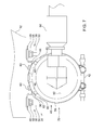
- FIG. 6 is a rear elevation view showing the attenuator mounted to the mounting bracket
- FIG. 7 is a right-hand side elevation view showing the attenuator mounted to the mounting bracket
- FIG. 8 is a top view showing the mounting bracket and the attenuator mounted thereto.
- FIG. 9 is a rear elevation view showing a coupler for mounting the attenuator to the mounting bracket.
- a self-propelled work vehicle 10 is configured as a motor grader comprising a front section 11 and a rear section 12 , the front and rear sections 11 , 12 articulated to one another.
- the front section 11 comprises an operator's station 13 (e.g., cab) from which a human operator can operate the vehicle 10 .
- the rear section 12 comprises a chassis 14 , a compartment 15 , a vibratory power unit 16 , a fluid pump 18 , a fluid attenuator 20 , and a rigid tube 22 .
- the vibratory power unit 16 is positioned in the compartment 15 and is mounted in isolation to the chassis 14 to move in vibration relative to the chassis 14 .
- the pump 18 and the attenuator 20 are mounted to the vibratory power unit 16 also to move in vibration relative to the chassis 14 .
- the rigid tube 22 interconnects the pump 18 and the attenuator 20 for fluid communication therebetween. Such an arrangement promotes compact packaging in the compartment 15 , which may be particularly useful for accommodating the addition of emissions abatement equipment 64 in the compartment 15 .
- the rear section 12 comprises ground-engaging traction elements 23 supporting the chassis 14 for propulsion of the vehicle 10 along the ground, as shown diagrammatically, for example, in FIG. 1 .
- the traction elements 23 are wheels (e.g., four wheels), and the front section 11 also comprises wheels (e.g., two).
- the traction elements may include tracks as in a track-type vehicle.
- the machine 10 may comprise a hydraulic system comprising the pump 18 and the attenuator 20 .
- the pump 18 may be a hydraulic pump
- the attenuator 20 may be a hydraulic attenuator.
- the rigid tube 22 is made of a rigid material, such as, for example, steel, promoting its reliability.
- the rigid tube 22 and the attenuator 20 are included in a fluid line 84 leading downstream from the pump 18 , the fluid line 84 being a hydraulic line when it is included in the hydraulic system.
- the attenuator 20 comprises a hollow tubular main attenuating body 86 , a first end face 88 , and a second end face 90 .
- the first and second end faces 88 , 90 are attached to opposite ends of the main attenuating body 86 .
- the attenuator 20 comprises an inlet 92 in the first end face 88 and an outlet 94 in the second end face 90 .
- the inlet 88 is coupled fluidly to the rigid tube 22 .
- the outlet 92 is coupled fluidly to a hose 96 included in the line 84 so as to conduct fluid away from the attenuator 20 .
- the main attenuating body 86 has a larger inner diameter than the rigid tube 22 and the hose 96 ; stated otherwise, the main attenuating body 86 has a larger internal cross-sectional area than the internal cross-sectional area of each of the rigid tube 22 and the hose 96 leading to lower fluid velocities.
- the attenuator 20 is thus capable of attenuating pressure pulsations in the fluid from the pump 18 as the fluid flows in the line 84 from the rigid tube 22 to the hose 96 .
- the vibratory power unit 16 may comprise an engine 24 and a transmission 26 .
- the housing of the engine 24 and the housing of the transmission 26 are fixed to one another against movement relative to one another.
- the engine 24 and the transmission 26 are positioned in the compartment 15 .
- the compartment 15 may thus be the engine compartment of the machine 10 .
- the attenuator 20 is mounted with the engine 24 and the transmission 26 to move in vibration relative to the chassis 14 .
- the engine 24 may be an internal combustion engine (e.g., compression ignition such as diesel; spark ignition).
- the vibratory power unit 16 is mounted to the chassis 14 to move in vibration relative to the chassis 14 . Vibration of the vibratory power unit 16 is dampened between the vibratory power unit 16 and the chassis 14 so as to minimize any transfer of vibration from the vibratory power unit 16 to the chassis 14 .
- the vibratory power unit 16 is thus isolation-mounted to the chassis 14 so as to be isolated from the chassis 14 .
- each isolation unit comprises an inverted L-shaped bracket that “floats” on the chassis 14 and to which the transmission 26 is fastened (e.g., bolted with four bolts and a respective washer for each bolt).
- the L-shaped bracket has a first leg extending over a box beam 28 of the chassis 14 and a second leg depending from the first leg laterally inboard of that beam 28 .
- Each isolation unit further comprises two compressible units.
- Each compressible unit comprises an upper compressible ring, a lower compressible ring, a bolt, and a washer.
- Each compressible ring is made of compressible material such as, for example, rubber.
- the upper and lower compressible rings are positioned respectively above and below the first leg of the L-shaped bracket.
- the bolt extends downwardly in sequence from its head through the washer, the upper compressible ring, the first leg of the L-shaped bracket, the second compressible ring, and into a lug of the chasses 12 and an angle gusset.
- the lug of the chassis 14 comprises a lug portion of a top plate of the box beam 28 and a lug plate welded onto the top of the top plate lug portion.
- the angle gusset extends between and is welded onto the underside of the top plate and a laterally inboard vertical plate of the box beam 28 .
- the bolt is threaded to any one or more of the lug plate, the top plate lug portion, and the angle gusset (e.g., all three).
- the engine 24 may be isolation-mounted to the chassis 14 .
- the pump 18 is mounted to the transmission 26 .
- the housing of the pump 18 is fixed to the housing of the transmission 26 against movement relative thereto.
- the attenuator 20 is mounted to the engine 24 .
- the vibratory power unit 16 comprises a mounting bracket 29 .
- the attenuator 20 is mounted to the mounting bracket 29 , and the mounting bracket 29 is mounted to the engine 24 .
- the mounting bracket 29 comprises, for example, a first arm 30 , a second arm 30 , and a platform 32 .
- the first and second arms 30 are mounted to and depend from the engine 24 .
- the first and second arms 30 are fastened or otherwise secured to the engine housing.
- Each arm 30 is fastened to the engine housing.
- the platform 32 interconnects the first and second arms 30 .
- the mounting bracket 29 is, for example, U-shaped and configured as a one-piece metal structure.
- Each arm 30 is angled to accommodate packaging constraints.
- the arm 30 comprises a proximal portion 76 extending from the platform 32 , a distal portion 78 distal from the platform 32 , and an elbow 80 positioned between the proximal portion 76 and the distal portion 78 .
- the distal portion 80 is fastened to the engine housing with, for example, two bolts and respective washers (one for each bolt), and is generally vertical.
- the arm 30 makes a turn at the elbow 80 such that the proximal portion 76 angles rearwardly and downwardly from the elbow 80 to the platform 32 .
- the platform 32 is clear of an axle 82 in the driveline of the work vehicle 10 .
- the attenuator 20 is mounted to the platform 32 by use of, for example, two couplers 34 of the work vehicle 10 .
- Each coupler 34 comprises a support bracket 36 , two fastener units 38 fastening the support bracket 36 to the platform 32 , and a strap unit 40 positioned around the attenuator 20 and threadedly tightened with a tightening device 42 of the strap unit 40 .
- the support bracket 36 comprises a generally W-shaped deck 44 , two feet 46 attached to and underlying the bottom of the deck 44 and positioned on the attenuator 20 , and two flanges 48 extending outwardly from respectively opposite side legs of the deck 44 (e.g., the deck 44 and flanges 48 are part of the same formed plate).
- Each foot 46 is made, for example, of a compressible material (e.g., rubber).
- Each fastener unit 38 fastens a respective flange 48 to the platform 32 .
- the fastener unit 38 comprises a threaded bolt 50 , a washer 52 , a grommet 54 (made, for example, of a compressible material such as rubber), and a nut 58 .
- the grommet 54 is positioned in a hole of the platform 32 and a hole in the flange 48 and comprises an annular portion extending between the platform 32 and the flange 48 so as to be compressed therebetween.
- the bolt 50 extends through the washer 52 and the grommet 54 , and thus through the holes in the platform and the flange 48 .
- the washer 52 is positioned between the head of the bolt 50 and the grommet 54 .
- the nut 58 is threaded onto the bolt 50 against the flange 48 .
- the strap unit 40 straps a respective end portion of the attenuator 20 to the support bracket 36 .
- the strap unit 40 comprises a strap 50 and the tightening device 42 .
- the strap 59 comprises a central band 62 and two side strips 60 .
- the two side strips 60 are attached respectively to opposite side edges of the central band 62 .
- Each side strip 60 is made, for example, of a compressible material (e.g., rubber) and is generally U-shaped so as to fit over a respective side edge of the band 62 and contact an outer surface of the attenuator 20 .
- the central band 62 extends over the deck 44 thereon.
- the tightening device 42 tightens the straps strap 59 onto the respective end portion of the attenuator 20 so as to secure the attenuator 20 to the support bracket 36 .
- Each foot 46 comprises a finger 63 that extends upwardly through a respective hole in the deck 44 and over the central band 62 to facilitate positioning of the band 62 on the deck 44 .
- the platform 32 comprises a hole 63 , reducing the weight of the mounting bracket 29 .
- the fastener units 38 are positioned about the hole 63 .
- the hole 63 is generally octagonal, and the fastener units 38 are positioned symmetrically about the hole 63 at respective sides of the octagon.
- the attenuator 20 may be mounted to the transmission 26 or other components of the vibratory power unit 16 .
- the work vehicle 10 may comprise emissions abatement equipment 64 positioned in the compartment 15 .
- That emissions abatement equipment 64 may comprise, for example, a DOC 66 , a DPF 67 downstream of the DOC 66 , an SCR catalyst 68 downstream of the DPF 67 , and an AOC 70 downstream of the SCR catalyst 68 .
- a DEF tank 72 of the work vehicle 10 is coupled fluidly to the exhaust line between the DPF 67 and the SCR catalyst 68 .
- the work vehicle 10 may comprise an air cleaner 74 positioned in the compartment 15 .
- the air cleaner 70 is positioned upstream of the engine 24 to remove contaminants from air before ingestion of the air by the engine 24 .
- the work vehicle 10 may take the form of any work vehicle or work machine.
- FIGS. 1 and 3 represent perforation fields (e.g., screens), which may take on a wide variety of shapes and sizes.
- the rear section 12 may include other perforation fields.
Landscapes
- Engineering & Computer Science (AREA)
- General Engineering & Computer Science (AREA)
- Mechanical Engineering (AREA)
- Mining & Mineral Resources (AREA)
- Civil Engineering (AREA)
- Structural Engineering (AREA)
- Physics & Mathematics (AREA)
- Fluid Mechanics (AREA)
- Vibration Prevention Devices (AREA)
Abstract
Description
Claims (14)
Priority Applications (2)
| Application Number | Priority Date | Filing Date | Title |
|---|---|---|---|
| US13/848,492 US8991546B2 (en) | 2013-03-21 | 2013-03-21 | Work vehicle with fluid attentuator |
| CN201320467510.0U CN203477175U (en) | 2013-03-21 | 2013-08-01 | Operating vehicle with fluid attenuator |
Applications Claiming Priority (1)
| Application Number | Priority Date | Filing Date | Title |
|---|---|---|---|
| US13/848,492 US8991546B2 (en) | 2013-03-21 | 2013-03-21 | Work vehicle with fluid attentuator |
Publications (2)
| Publication Number | Publication Date |
|---|---|
| US20140284131A1 US20140284131A1 (en) | 2014-09-25 |
| US8991546B2 true US8991546B2 (en) | 2015-03-31 |
Family
ID=50225509
Family Applications (1)
| Application Number | Title | Priority Date | Filing Date |
|---|---|---|---|
| US13/848,492 Active 2033-04-12 US8991546B2 (en) | 2013-03-21 | 2013-03-21 | Work vehicle with fluid attentuator |
Country Status (2)
| Country | Link |
|---|---|
| US (1) | US8991546B2 (en) |
| CN (1) | CN203477175U (en) |
Families Citing this family (1)
| Publication number | Priority date | Publication date | Assignee | Title |
|---|---|---|---|---|
| US9347362B2 (en) * | 2014-09-12 | 2016-05-24 | Cummins Emission Solutions, Inc. | Adjustable mounting system for aftertreatment or exhaust components |
Citations (29)
| Publication number | Priority date | Publication date | Assignee | Title |
|---|---|---|---|---|
| US2747564A (en) * | 1955-04-29 | 1956-05-29 | Julius J Wehling | Oiling apparatus |
| US2943641A (en) | 1956-01-30 | 1960-07-05 | Richfield Oil Corp | Device for attenuating pulsative flow in gases |
| US3323305A (en) | 1964-10-16 | 1967-06-06 | Gen Motors Corp | Attenuating device |
| US3412279A (en) | 1965-09-13 | 1968-11-19 | Varian Associates | Electromagnetic wave energy absorbing elements for use in high frequency electron discharge devices having traveling wave tube sections |
| US3708977A (en) * | 1970-12-31 | 1973-01-09 | Int Basic Economy Corp | Hydraulic power unit |
| US3894603A (en) * | 1972-08-29 | 1975-07-15 | Caterpillar Tractor Co | Vehicle drive train |
| US4021341A (en) | 1974-02-19 | 1977-05-03 | Cosentino Louis C | Hemodialysis ultrafiltration system |
| US4081050A (en) * | 1977-02-02 | 1978-03-28 | International Harvester Company | Front engine tractor having transverse midship mounted heat exchanger |
| US4473043A (en) * | 1980-08-19 | 1984-09-25 | Kabushiki Kaisha Komatsu Seisakusho | Fluid lubricating circuit for engines |
| US4507063A (en) * | 1981-09-03 | 1985-03-26 | Robert Bosch Gmbh | Gas-filled damping element for damping pressure pulsations |
| US4642035A (en) | 1984-01-23 | 1987-02-10 | Deere & Company | Cross loop attenuator for hydraulic systems |
| US4888962A (en) * | 1989-01-06 | 1989-12-26 | Tecumseh Products Company | Suction accumulator strap |
| US5312174A (en) | 1989-04-22 | 1994-05-17 | Alfred Teves Gmbh | Slip-controlled brake system, especially for use with automotive vehicles |
| US5353840A (en) * | 1991-08-23 | 1994-10-11 | Hydraulic Power Systems, Inc. | Pressure response type pulsation damper noise attenuator and accumulator |
| US5791141A (en) * | 1994-04-29 | 1998-08-11 | Techco Corp. | Method and apparatus for reduction of fluid borne noise in hydraulic systems |
| US6004119A (en) * | 1996-07-17 | 1999-12-21 | Koyo Seiko Co., Ltd. | Motor-driven hydraulic gear pump having a noise damper |
| US6041618A (en) * | 1997-10-31 | 2000-03-28 | Automotive Fluid Systems, Inc. | Insulated pressure vessel holder |
| US6309187B1 (en) * | 1999-03-17 | 2001-10-30 | Visteon Global Technologies, Inc. | Hydraulic gear pump power pack for a power steering system with an integral pressure wave attenuator for fluid noise reduction |
| US6419537B1 (en) | 2001-02-20 | 2002-07-16 | Brunswick Corporation | Sound attenuator and temperature control device for an outboard motor |
| US20030042391A1 (en) * | 2001-08-31 | 2003-03-06 | Honda Giken Kogyo Kabushiki Kaisha | Engine auxiliary equipment mounting construction |
| US20030159876A1 (en) | 2000-01-28 | 2003-08-28 | Philippe Drouet | Noise reducing fluid tranfer hose, in particular for a motor vehicle power steering controlled system |
| US6854269B2 (en) * | 2002-07-23 | 2005-02-15 | Caterpillar Inc. | Noise attenuation in a hydraulic circuit |
| US6866066B2 (en) * | 2000-11-16 | 2005-03-15 | Hydac Technology Gmbh | Hydraulic accumulator |
| US20080134675A1 (en) * | 2006-12-12 | 2008-06-12 | Grigoriy Epshteyn | Monocylindrical hybrid powertrain and method of operation |
| US7506619B1 (en) * | 2007-10-12 | 2009-03-24 | Freudenberg-Nok General Partnership | Tunable hybrid bracket assembly |
| US20100018199A1 (en) * | 2005-12-08 | 2010-01-28 | Airbus Deutschland Gmbh | Device for Reducing Hydraulic-Fluid Oscillation in a Hydraulic System |
| US7836967B2 (en) * | 2008-07-28 | 2010-11-23 | Caterpillar Inc | Cooling system packaging arrangement for a machine |
| US20120061552A1 (en) * | 2010-09-14 | 2012-03-15 | Haehn Craig S | Component orientation element |
| US20130251557A1 (en) * | 2012-03-20 | 2013-09-26 | Kabushiki Kaisha Toyota Jidoshokki | Motor-driven compressor |
-
2013
- 2013-03-21 US US13/848,492 patent/US8991546B2/en active Active
- 2013-08-01 CN CN201320467510.0U patent/CN203477175U/en not_active Expired - Lifetime
Patent Citations (29)
| Publication number | Priority date | Publication date | Assignee | Title |
|---|---|---|---|---|
| US2747564A (en) * | 1955-04-29 | 1956-05-29 | Julius J Wehling | Oiling apparatus |
| US2943641A (en) | 1956-01-30 | 1960-07-05 | Richfield Oil Corp | Device for attenuating pulsative flow in gases |
| US3323305A (en) | 1964-10-16 | 1967-06-06 | Gen Motors Corp | Attenuating device |
| US3412279A (en) | 1965-09-13 | 1968-11-19 | Varian Associates | Electromagnetic wave energy absorbing elements for use in high frequency electron discharge devices having traveling wave tube sections |
| US3708977A (en) * | 1970-12-31 | 1973-01-09 | Int Basic Economy Corp | Hydraulic power unit |
| US3894603A (en) * | 1972-08-29 | 1975-07-15 | Caterpillar Tractor Co | Vehicle drive train |
| US4021341A (en) | 1974-02-19 | 1977-05-03 | Cosentino Louis C | Hemodialysis ultrafiltration system |
| US4081050A (en) * | 1977-02-02 | 1978-03-28 | International Harvester Company | Front engine tractor having transverse midship mounted heat exchanger |
| US4473043A (en) * | 1980-08-19 | 1984-09-25 | Kabushiki Kaisha Komatsu Seisakusho | Fluid lubricating circuit for engines |
| US4507063A (en) * | 1981-09-03 | 1985-03-26 | Robert Bosch Gmbh | Gas-filled damping element for damping pressure pulsations |
| US4642035A (en) | 1984-01-23 | 1987-02-10 | Deere & Company | Cross loop attenuator for hydraulic systems |
| US4888962A (en) * | 1989-01-06 | 1989-12-26 | Tecumseh Products Company | Suction accumulator strap |
| US5312174A (en) | 1989-04-22 | 1994-05-17 | Alfred Teves Gmbh | Slip-controlled brake system, especially for use with automotive vehicles |
| US5353840A (en) * | 1991-08-23 | 1994-10-11 | Hydraulic Power Systems, Inc. | Pressure response type pulsation damper noise attenuator and accumulator |
| US5791141A (en) * | 1994-04-29 | 1998-08-11 | Techco Corp. | Method and apparatus for reduction of fluid borne noise in hydraulic systems |
| US6004119A (en) * | 1996-07-17 | 1999-12-21 | Koyo Seiko Co., Ltd. | Motor-driven hydraulic gear pump having a noise damper |
| US6041618A (en) * | 1997-10-31 | 2000-03-28 | Automotive Fluid Systems, Inc. | Insulated pressure vessel holder |
| US6309187B1 (en) * | 1999-03-17 | 2001-10-30 | Visteon Global Technologies, Inc. | Hydraulic gear pump power pack for a power steering system with an integral pressure wave attenuator for fluid noise reduction |
| US20030159876A1 (en) | 2000-01-28 | 2003-08-28 | Philippe Drouet | Noise reducing fluid tranfer hose, in particular for a motor vehicle power steering controlled system |
| US6866066B2 (en) * | 2000-11-16 | 2005-03-15 | Hydac Technology Gmbh | Hydraulic accumulator |
| US6419537B1 (en) | 2001-02-20 | 2002-07-16 | Brunswick Corporation | Sound attenuator and temperature control device for an outboard motor |
| US20030042391A1 (en) * | 2001-08-31 | 2003-03-06 | Honda Giken Kogyo Kabushiki Kaisha | Engine auxiliary equipment mounting construction |
| US6854269B2 (en) * | 2002-07-23 | 2005-02-15 | Caterpillar Inc. | Noise attenuation in a hydraulic circuit |
| US20100018199A1 (en) * | 2005-12-08 | 2010-01-28 | Airbus Deutschland Gmbh | Device for Reducing Hydraulic-Fluid Oscillation in a Hydraulic System |
| US20080134675A1 (en) * | 2006-12-12 | 2008-06-12 | Grigoriy Epshteyn | Monocylindrical hybrid powertrain and method of operation |
| US7506619B1 (en) * | 2007-10-12 | 2009-03-24 | Freudenberg-Nok General Partnership | Tunable hybrid bracket assembly |
| US7836967B2 (en) * | 2008-07-28 | 2010-11-23 | Caterpillar Inc | Cooling system packaging arrangement for a machine |
| US20120061552A1 (en) * | 2010-09-14 | 2012-03-15 | Haehn Craig S | Component orientation element |
| US20130251557A1 (en) * | 2012-03-20 | 2013-09-26 | Kabushiki Kaisha Toyota Jidoshokki | Motor-driven compressor |
Non-Patent Citations (1)
| Title |
|---|
| Background Information (1 page)(admitted as prior art before Mar. 21, 2013). |
Also Published As
| Publication number | Publication date |
|---|---|
| US20140284131A1 (en) | 2014-09-25 |
| CN203477175U (en) | 2014-03-12 |
Similar Documents
| Publication | Publication Date | Title |
|---|---|---|
| US8997915B2 (en) | Wheel loader | |
| CN101614148B (en) | Construction machinery | |
| CN104520551B (en) | Supporting mechanism, exhaust treatment unit and wheel loader | |
| US9688134B2 (en) | Exhaust system for an off-road vehicle | |
| CN104254674A (en) | Exhaust gas treatment unit and working vehicle having exhaust gas treatment unit mounted thereon | |
| JP6487270B2 (en) | Exhaust gas purification device | |
| JP2018168847A (en) | Tractor | |
| US9347350B2 (en) | Engine unit | |
| US8991546B2 (en) | Work vehicle with fluid attentuator | |
| JP5894342B2 (en) | Dump truck | |
| US11738814B2 (en) | Work vehicle | |
| JP5864036B1 (en) | Dump truck | |
| WO2017078011A1 (en) | Work vehicle | |
| US6182447B1 (en) | Exhaust pipe structure for vehicle | |
| JP2016075211A (en) | Engine device | |
| JPS6332782Y2 (en) | ||
| US20220096973A1 (en) | Filter attachment body and work vehicle | |
| JP4634858B2 (en) | Selective reduction NOx catalyst system for snow removal truck | |
| CN216554081U (en) | Vehicle urea case mounting structure and vehicle | |
| JPH0111583Y2 (en) | ||
| JPH0117495Y2 (en) | ||
| JP3633393B2 (en) | Exhaust structure of vertical internal combustion engine | |
| JP6343219B2 (en) | Engine equipment | |
| JP2015025393A (en) | Exhaust pipe structure of construction machine | |
| JPH0139784Y2 (en) |
Legal Events
| Date | Code | Title | Description |
|---|---|---|---|
| AS | Assignment |
Owner name: ENTEGEE, INC., FLORIDA Free format text: ASSIGNMENT OF ASSIGNORS INTEREST;ASSIGNOR:GINSTERBLUM, RICHARD J.;REEL/FRAME:030381/0029 Effective date: 20130418 Owner name: DEERE & COMPANY, ILLINOIS Free format text: ASSIGNMENT OF ASSIGNORS INTEREST;ASSIGNOR:ENTEGEE, INC.;REEL/FRAME:030381/0104 Effective date: 20130502 Owner name: DEERE & COMPANY, ILLINOIS Free format text: ASSIGNMENT OF ASSIGNORS INTEREST;ASSIGNORS:HULL, MARK E.;FLATLEY, ZACHARY T.;REEL/FRAME:030380/0972 Effective date: 20130405 |
|
| STCF | Information on status: patent grant |
Free format text: PATENTED CASE |
|
| MAFP | Maintenance fee payment |
Free format text: PAYMENT OF MAINTENANCE FEE, 4TH YEAR, LARGE ENTITY (ORIGINAL EVENT CODE: M1551); ENTITY STATUS OF PATENT OWNER: LARGE ENTITY Year of fee payment: 4 |
|
| MAFP | Maintenance fee payment |
Free format text: PAYMENT OF MAINTENANCE FEE, 8TH YEAR, LARGE ENTITY (ORIGINAL EVENT CODE: M1552); ENTITY STATUS OF PATENT OWNER: LARGE ENTITY Year of fee payment: 8 |