EP0419817B1 - Mehrtemperaturen-Kühlschrank - Google Patents
Mehrtemperaturen-Kühlschrank Download PDFInfo
- Publication number
- EP0419817B1 EP0419817B1 EP90115153A EP90115153A EP0419817B1 EP 0419817 B1 EP0419817 B1 EP 0419817B1 EP 90115153 A EP90115153 A EP 90115153A EP 90115153 A EP90115153 A EP 90115153A EP 0419817 B1 EP0419817 B1 EP 0419817B1
- Authority
- EP
- European Patent Office
- Prior art keywords
- housing
- distributor
- compartments
- refrigerator according
- heat exchanger
- Prior art date
- Legal status (The legal status is an assumption and is not a legal conclusion. Google has not performed a legal analysis and makes no representation as to the accuracy of the status listed.)
- Expired - Lifetime
Links
Images


Classifications
-
- F—MECHANICAL ENGINEERING; LIGHTING; HEATING; WEAPONS; BLASTING
- F25—REFRIGERATION OR COOLING; COMBINED HEATING AND REFRIGERATION SYSTEMS; HEAT PUMP SYSTEMS; MANUFACTURE OR STORAGE OF ICE; LIQUEFACTION SOLIDIFICATION OF GASES
- F25D—REFRIGERATORS; COLD ROOMS; ICE-BOXES; COOLING OR FREEZING APPARATUS NOT OTHERWISE PROVIDED FOR
- F25D17/00—Arrangements for circulating cooling fluids; Arrangements for circulating gas, e.g. air, within refrigerated spaces
- F25D17/04—Arrangements for circulating cooling fluids; Arrangements for circulating gas, e.g. air, within refrigerated spaces for circulating air, e.g. by convection
- F25D17/042—Air treating means within refrigerated spaces
- F25D17/045—Air flow control arrangements
-
- F—MECHANICAL ENGINEERING; LIGHTING; HEATING; WEAPONS; BLASTING
- F25—REFRIGERATION OR COOLING; COMBINED HEATING AND REFRIGERATION SYSTEMS; HEAT PUMP SYSTEMS; MANUFACTURE OR STORAGE OF ICE; LIQUEFACTION SOLIDIFICATION OF GASES
- F25D—REFRIGERATORS; COLD ROOMS; ICE-BOXES; COOLING OR FREEZING APPARATUS NOT OTHERWISE PROVIDED FOR
- F25D17/00—Arrangements for circulating cooling fluids; Arrangements for circulating gas, e.g. air, within refrigerated spaces
- F25D17/04—Arrangements for circulating cooling fluids; Arrangements for circulating gas, e.g. air, within refrigerated spaces for circulating air, e.g. by convection
- F25D17/06—Arrangements for circulating cooling fluids; Arrangements for circulating gas, e.g. air, within refrigerated spaces for circulating air, e.g. by convection by forced circulation
- F25D17/062—Arrangements for circulating cooling fluids; Arrangements for circulating gas, e.g. air, within refrigerated spaces for circulating air, e.g. by convection by forced circulation in household refrigerators
- F25D17/065—Arrangements for circulating cooling fluids; Arrangements for circulating gas, e.g. air, within refrigerated spaces for circulating air, e.g. by convection by forced circulation in household refrigerators with compartments at different temperatures
-
- F—MECHANICAL ENGINEERING; LIGHTING; HEATING; WEAPONS; BLASTING
- F25—REFRIGERATION OR COOLING; COMBINED HEATING AND REFRIGERATION SYSTEMS; HEAT PUMP SYSTEMS; MANUFACTURE OR STORAGE OF ICE; LIQUEFACTION SOLIDIFICATION OF GASES
- F25D—REFRIGERATORS; COLD ROOMS; ICE-BOXES; COOLING OR FREEZING APPARATUS NOT OTHERWISE PROVIDED FOR
- F25D27/00—Lighting arrangements
-
- F—MECHANICAL ENGINEERING; LIGHTING; HEATING; WEAPONS; BLASTING
- F25—REFRIGERATION OR COOLING; COMBINED HEATING AND REFRIGERATION SYSTEMS; HEAT PUMP SYSTEMS; MANUFACTURE OR STORAGE OF ICE; LIQUEFACTION SOLIDIFICATION OF GASES
- F25D—REFRIGERATORS; COLD ROOMS; ICE-BOXES; COOLING OR FREEZING APPARATUS NOT OTHERWISE PROVIDED FOR
- F25D2317/00—Details or arrangements for circulating cooling fluids; Details or arrangements for circulating gas, e.g. air, within refrigerated spaces, not provided for in other groups of this subclass
- F25D2317/06—Details or arrangements for circulating cooling fluids; Details or arrangements for circulating gas, e.g. air, within refrigerated spaces, not provided for in other groups of this subclass with forced air circulation
- F25D2317/065—Details or arrangements for circulating cooling fluids; Details or arrangements for circulating gas, e.g. air, within refrigerated spaces, not provided for in other groups of this subclass with forced air circulation characterised by the air return
- F25D2317/0653—Details or arrangements for circulating cooling fluids; Details or arrangements for circulating gas, e.g. air, within refrigerated spaces, not provided for in other groups of this subclass with forced air circulation characterised by the air return through the mullion
-
- F—MECHANICAL ENGINEERING; LIGHTING; HEATING; WEAPONS; BLASTING
- F25—REFRIGERATION OR COOLING; COMBINED HEATING AND REFRIGERATION SYSTEMS; HEAT PUMP SYSTEMS; MANUFACTURE OR STORAGE OF ICE; LIQUEFACTION SOLIDIFICATION OF GASES
- F25D—REFRIGERATORS; COLD ROOMS; ICE-BOXES; COOLING OR FREEZING APPARATUS NOT OTHERWISE PROVIDED FOR
- F25D2317/00—Details or arrangements for circulating cooling fluids; Details or arrangements for circulating gas, e.g. air, within refrigerated spaces, not provided for in other groups of this subclass
- F25D2317/06—Details or arrangements for circulating cooling fluids; Details or arrangements for circulating gas, e.g. air, within refrigerated spaces, not provided for in other groups of this subclass with forced air circulation
- F25D2317/065—Details or arrangements for circulating cooling fluids; Details or arrangements for circulating gas, e.g. air, within refrigerated spaces, not provided for in other groups of this subclass with forced air circulation characterised by the air return
- F25D2317/0654—Details or arrangements for circulating cooling fluids; Details or arrangements for circulating gas, e.g. air, within refrigerated spaces, not provided for in other groups of this subclass with forced air circulation characterised by the air return through the side
-
- F—MECHANICAL ENGINEERING; LIGHTING; HEATING; WEAPONS; BLASTING
- F25—REFRIGERATION OR COOLING; COMBINED HEATING AND REFRIGERATION SYSTEMS; HEAT PUMP SYSTEMS; MANUFACTURE OR STORAGE OF ICE; LIQUEFACTION SOLIDIFICATION OF GASES
- F25D—REFRIGERATORS; COLD ROOMS; ICE-BOXES; COOLING OR FREEZING APPARATUS NOT OTHERWISE PROVIDED FOR
- F25D2317/00—Details or arrangements for circulating cooling fluids; Details or arrangements for circulating gas, e.g. air, within refrigerated spaces, not provided for in other groups of this subclass
- F25D2317/06—Details or arrangements for circulating cooling fluids; Details or arrangements for circulating gas, e.g. air, within refrigerated spaces, not provided for in other groups of this subclass with forced air circulation
- F25D2317/067—Details or arrangements for circulating cooling fluids; Details or arrangements for circulating gas, e.g. air, within refrigerated spaces, not provided for in other groups of this subclass with forced air circulation characterised by air ducts
-
- F—MECHANICAL ENGINEERING; LIGHTING; HEATING; WEAPONS; BLASTING
- F25—REFRIGERATION OR COOLING; COMBINED HEATING AND REFRIGERATION SYSTEMS; HEAT PUMP SYSTEMS; MANUFACTURE OR STORAGE OF ICE; LIQUEFACTION SOLIDIFICATION OF GASES
- F25D—REFRIGERATORS; COLD ROOMS; ICE-BOXES; COOLING OR FREEZING APPARATUS NOT OTHERWISE PROVIDED FOR
- F25D2400/00—General features of, or devices for refrigerators, cold rooms, ice-boxes, or for cooling or freezing apparatus not covered by any other subclass
- F25D2400/04—Refrigerators with a horizontal mullion
Definitions
- the invention relates to a multi-temperature refrigerator according to the preamble of claim 1.
- a refrigerator is known from US-A-4 539 819.
- thermostatically controlled control flaps for regulating the different operating temperatures prevailing in the various subjects in the air ducts running in the walls, floors or ceilings of the heat-insulated housing.
- the invention has for its object to improve the structure of the cooling devices specified in the introduction by simple measures and in particular to solve the problems associated with the installation of the control flaps and their drive cheap.
- the distributor as an essentially cuboid body is formed, which is fitted in the rear area under the intermediate floor receiving the heat exchanger in the niche formed by the side walls and the rear wall of the housing and is provided with connection openings for the air channels running there.
- the plug of specifically heavy cold air that forms in a siphon of this type prevents in a simple manner that warmer air rising in the channel can reach the compartment above it.
- the channels are equipped with pocket-shaped separators for condensation water located in front of the control flaps in the direction of flow.
- a construction has proven to be particularly favorable according to which the distributor is equipped with a lighting device for the compartment accommodating it.
- a multi-temperature refrigerator 10 with a heat-insulated housing 11 has compartments of different temperatures thermally separated from one another by intermediate shelves 12 and 13 or a separating plate 14 - such as a freezer compartment 15, a so-called zero-degree compartment 16 and at temperatures of + 5 ° C and + 10 ° C operated cooling compartments 17 and 18.
- the freezer compartment 15 is arranged on top in the housing 10, while the zero-degree compartment 16 and the cooling compartments 17 and 18 operated at + 5 ° C. and + 10 ° C. are in the order listed below.
- the individual compartments of different temperatures can be closed with heat-insulated doors 19 and 19 'or with heat-insulated front panels 20 and 20' on drawer-like pull-outs in the cooling compartments 17 and 18 below, which are not shown here.
- the multi-temperature refrigerator 10 is equipped in a known manner with an electric motor-driven compressor cooling unit, the individual components of which, for the sake of simplicity, only the encapsulated motor compressor 22 arranged in a machine compartment 21 in the base of the heat-insulated housing 10 and the one in the heat-insulated intermediate floor 12 between the freezer compartment 15 and the zero-degree compartment 16 are shown cold-side heat exchangers 23 designed as lamella evaporators. This is forced-ventilated by means of an electric motor-operated fan 24.
- the intermediate floor 12 between the freezer compartment 15 and the zero-degree compartment 16 is for receiving the heat exchanger 23 and the blower 24 and various auxiliary units, not shown, such as a defrost heater and the like.
- air channels 25 in which the individual units are concealed and invisible from the outside.
- the temperature level in the individual compartments of different temperatures is maintained with the aid of the cold air flow conveyed by the blower 24 via the heat exchanger 23, which is conducted via air channels 26 and 27 arranged in the side walls or the rear wall of the housing 10.
- the air supply to the individual compartments of different temperatures is controlled by thermostatically controlled regulating elements in the form of flap thermostats described in detail below controlled with controller flaps in the channels.
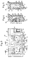
- the pressure-side air ducts 27 are formed in the illustrated and described embodiment by a trough-like molded part 28 arranged in the rear wall of the heat-insulated housing 10 and shown as an individual part in FIGS. 8 and 9, which with its open side from behind against the rear wall of the individual Inner container enclosing compartments of different temperatures and there corresponds with corresponding outlet openings.
- the trough-like molded part 28 receiving the pressure-side air ducts 27, which is used at the same time for mounting the blower 24 and is equipped for this purpose with a number of circularly arranged fastening pins 29, is described in more detail below in connection with FIGS. 8 and 9 and in explained its function.
- a valve thermostat which is used in a distributor 30 which can be inserted into the housing 10 as a preassembled unit serves as the usual type of regulator with regulator flaps 31, each with an electromotive drive 32 also arranged in the distributor 30 (see FIGS. 4 and 6) ) are driven.
- the same position numbers are used for corresponding parts.
- the distributor 30 is designed as a substantially cuboid body, which is fitted in the rear area under the intermediate floor 12 receiving the heat exchanger 23 and the fan 24 in the niche formed by the side walls and the rear wall of the housing 10 and with connection openings 33, 34 and 35 is equipped for the corresponding air ducts.
- the distributor piece 30 is formed from two nested and tightly interlocked mold parts 36 and 37 made of rigid plastic foam, which accommodate cavities for air channels 38 or chambers 39 for installing the electromotive drive 32 of the controller flaps 31.
- the distributor 30 On its front side, the distributor 30 is covered with a plastic shell 40, in the recessed lower area of which outlet openings 41 are arranged for the air channels 38 emerging here.
- the distributor 30 On the lower rear edge of the plastic shell 40 there are also eyes 42 which are used to fasten the distributor 30 to the rear wall of the housing 10 and serve in the trough-like molded part 28 with the air channels 27 therein.
- the air channels 38 located in the distributor 30 in the flow direction behind the control flaps 31 of the flap thermostats are siphon-like and are provided with a recess 43 for this purpose, into each of which a partition protrudes from above .
- the distributor 30 is also equipped with a lighting device arranged laterally in a recess 44 in the form of a lamp socket provided with an incandescent lamp 45 for the compartment 16 assigned to it.
- the electrical supply lines for the energy supply of the electromotive drives 32 of the flap thermostats are sunk on the back of the distributor 30 in a channel 46, from which they emerge laterally behind the lighting device. They are combined with their electrical leads to form a cable harness 47 which is provided with a common plug 48, the counterpart of which is not shown, is located in a wall of the housing 10.
- connection openings 33 to 34 of the distributor 30 are each surrounded by sealing frames 49 and 50, which consist of a sponge-like elastic material and ensure an airtight connection to the associated connections of the air channels in the rear wall of the housing 10 and in the intermediate floor 12.
- the sealing frames also perform the task of occasionally absorbing and binding condensation water forming in the air channels during the standstill phase of the fan 24, so that it cannot reach the control flaps 31.
- the condensation water that accumulates there is then evaporated by the resulting draft when the unit is next switched on, so that it is then deposited on the heat exchanger 23. If the condensation water is temporarily frozen, it nevertheless reaches the cold heat exchanger 23 by sublimation.
- the chambers 39 in the distributor 40 which accommodate the electromotive drives 32 of the flap thermostats, are sealed off with films 51 on the rear side thereof. Likewise, all external parting lines of the plastic molded parts 36 and 37 forming the distributor 30 are sealed with adhesive tapes (not shown).
- the air duct 27 on the rear of the housing 10 receiving molded part 28 has two outputs 52 and 53 assigned to the control flaps 31, in the vicinity of which a threshold 54 and 55 serving as a drip edge is arranged. With their help, condensation water forming on the wall of the molded part 28 is conducted into pocket-shaped separators 56 and 57 during the idle times of the fan 24 and collected there. At the lower edge of the exits of the air ducts there are aprons 58 which prevent condensation water from running into the gaps at the outlet openings of the air ducts in the rear wall of the housing 10.
Description
- Die Erfindung betrifft einen Mehrtemperaturen-Kühlschrank gemäß dem Oberbegriff des Anspruchs 1. Ein solcher Kühlschrank ist aus der US-A-4 539 819 bekannt.
- Bei bekannten Kühlgeräten der genannten Art ist es üblich, die thermostatisch gesteuerten Reglerklappen zur Regelung der in den verschiedenen Fächern herrschenden unterschiedlichen Betriebstemperatur versenkt in die in den Wänden, Böden oder Decken des wärmeisolierten Gehäuses verlaufende Luftkanäle einzubauen. Hierzu ist es jedoch erforderlich, die Reglerklappen räumlich weit voneinander entfernt einzeln zu montieren. Dies ist insbesondere bei Geräten mit großem Rauminhalt der Fall. Sofern es sich hierbei um elektromotorisch angetriebene Reglerklappen handelt, müssen die zur Stromversorgung notwendigen Leitungen über weite Strecken im Gehäuse verlegt werden. Insbesondere bei Mehrtemperaturen-Kühlschränken mit einer Vielzahl von Fächern unterschiedlicher Temperatur ist hierzu ein großer Montageaufwand erforderlich, zumal es üblich ist, die Reglerklappen ebenso wie die elektrischen Leitungen unauffällig und verdeckt im hinteren Bereich des Gehäuses im Gerät anzuordnen.
- Bei einer derart auseinandergezogenen Anordnung der Reglerklappen im hinteren Bereich des Gehäuses ist es auch schwierig, diese und deren Antrieb im Bedarfsfalle zu warten, einzuregeln oder deren Funktion zu überprüfen. Schließlich ist es bei der üblichen Einzelanordnung der Reglerklappen erforderlich, an entsprechenden Stellen in den Luftkanälen besondere Räume vorzusehen, in denen die Reglerklappen mit ihrem Antrieb montiert werden können. Hierdurch wird die Kanalführung im Gehäuse des Gerätes sehr kompliziert.
- Der Erfindung liegt die Aufgabe zugrunde, den Aufbau der eingangs näher bezeichneten Kühlgeräte durch einfache Maßnahmen zu verbessern und insbesondere die mit dem Einbau der Reglerklappen und deren Antrieb im Zusammenhang stehenden Probleme günstig zu lösen.
- Diese Aufgabe wird durch die Merkmale des kennzeichnenden Teils des Anspruchs 1 gelöst.
- Aufgrund der Zusammenfassung mehrerer Reglerklappen und deren Antriebe in einem als vormontierte Einheit in das Gehäuse einsetzbaren Verteiler gelingt es, die Konstruktion eines derartigen Gerätes besonders übersichtlich zu gestalten und dessen Montage und Wartung sehr zu vereinfachen.
- Bei einem Kühlgerät mit einem von Luftkanälen durchzogenen, den Wärmetauscher und ein Gebläse aufnehmenden Zwischenboden hat sich als besonders günstig erwiesen, wenn gemäß einer vorteilhaften Weiterbildung des Gegenstandes der Erfindung vorgesehen ist, daß der Verteiler als ein im wesentlichen quaderförmiger Körper ausgebildet ist, welcher im hinteren Bereich unter dem, den Wärmetauscher aufnehmenden Zwischenboden in der von den Seitenwänden und der Rückwand des Gehäuses gebildeten Nische eingepaßt und mit Anschlußöffnungen für die dort verlaufenden Luftkanäle versehen ist.
- Um zu vermeiden, daß sich bei Stillstand des Gebläses in den unteren Fächern sich erwärmende Luft durch die Kanäle in darüberliegende Fächer tieferer Temperatur aufsteigen kann und dort die Temperatur ansteigen läßt, ist nach einer weiteren vorteilhaften Ausgestaltung des Gegenstandes der Erfindung vorgesehen, daß im Verteiler angeordnete Kanäle in Strömungsrichtung hinter den Regelklappen siphonartig ausgebildet sind
- Der sich in einem deratigen Siphon bildende Pfropfen spezifisch schwerer Kaltluft verhindert dabei auf einfache Weise, daß in dem Kanal aufsteigende wärmere Luft nach oben in das darüberliegende Fach gelangen kann.
- Nach einer zusätzlichen vorteilhaften Weiterbildung des Gegenstandes der Erfindung ist vorgesehen, daß die Kanäle mit in Strömungsrichtung vor den Regelklappen gelegen, taschenförmigen Abscheider für Tauwasser ausgestattet sind.
- Hierdurch wird vermieden, daß sich während der Stillstandsphase des Gebläses an den Wänden der Kanäle niederschlagendes Tauwasser bis an die Reglerklappen gelangt, wo es in der nächsten Kühlphase gefrieren und dadurch die Regelklappen durch vereisen blockieren kann.
- Als besonders günstig hat sich eine Konstruktion erwiesen, nach der der Verteiler mit einer Beleuchtungseinrichtung für das ihn aufnehmende Fach ausgestattet ist.
- Weitere, in den Ansprüchen gekennzeichnete vorteilhafte Ausführungsformen der Erfindung sind in der nachfolgenden Beschreibung anhand eines in der beigefügten Zeichnung vereinfacht dargestellten Ausführungsbeispieles eines Mehrtemperaturen-Kühlschrankes erläutert. Es zeigen:
- Fig. 1
- in schematischer Darstellung einen Mehrtemperaturen-Kühlschrank mit einem im Zwischenboden zwischen seinem Gefrierfach und einem Null-Grad-Fach angeordneten, zwangsbelüfteten Wärmetauscher und einem im hinteren Bereich unter dem Zwischenboden in der von den Seitenwänden und der Rückwand seines wärmeisolierten Gehäuses gebildeten Nische eingepaßten, mit Anschlußöffnungen für dort verlaufende Luftkanäle versehenen und mit zwei Reglerklappen ausgestatteten Verteiler, wobei die den einzelnen Fächern zugeordneten Türen weggelassen sind,
- Fig. 2
- den Mehrtemperaturen-Kühlschrank nach Fig. 1 in einer Schnittansicht, von der Seite gesehen,
- Fig. 3
- den mit zwei Reglerklappen und deren Antrieb sowie mit ensprechenden Kanälen und Anschlüssen und zusätzlich mit einer Beleuchtungseinrichtung versehenen Verteiler, in der Ansicht von vorn, wobei Teile seiner Verkleidung und seiner Wärmeisolierung fortgelassen sind, um die dahinterliegende Einrichtung sichtbar zu machen,
- Fig. 4
- den Verteiler mit einer Reglerklappe und den entsprechenden Kanälen in einer Seitenansicht, geschnitten nach der Schnittlinie IV-IV in Fig. 3,
- Fig. 5
- eine weitere Schnittansicht des Verteilers mit den darin angeordneten Kanälen, geschnitten nach der Schnittlinie V-V in Fig. 3,
- Fig. 6
- den Verteiler mit den beiden Reglerklappen und deren Antrieb sowie der Beleuchtungseinrichtung in der Ansicht von hinten,
- Fig. 7
- den Verteiler mit der Beleuchtungseinrichtung und den in einem Stekker zusammengefaßen Versorgungsleitungen in der Ansicht von der Seite,
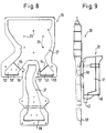
- Fig. 8
- als Einzelteil einen in der Rückwand des Gehäuses angeordneten wannenartigen Formteil mit einer Aufnahme für das Gebläse und den druckseitigen Luftkanälen, in der Ansicht von vorne und
- Fig. 9
- den Formteil nach Fig. 8 mit dem davorsitzenden Verteiler, in auseinandergezogener Darstellung, von der Seite gesehen.
- Ein Mehrtemperaturen-Kühlschrank 10 mit einem wärmeisolierten Gehäuse 11 weist in der üblichen Weise durch Zwischenböden 12 und 13 bzw. eine Trennplatte 14 thermisch voneinander getrennte Fächer unterschiedlicher Temperatur - wie ein Gefrierfach 15, ein sogenanntes Null-Grad-Fach 16 und bei Temperaturen von +5° C bzw. +10° C betriebene Kühlfächer 17 und 18 auf. Im vorliegenden Falle ist das Gefrierfach 15 im Gehäuse 10 obenliegend angeordnet, während das Null-Grad-Fach 16 und die mit +5° C bzw. +10° C betriebenen Kühlfächer 17 und 18 in der aufgezählten Reihenfolge darunter liegen. Die einzelnen Fächer unterschiedlicher Temperatur sind mit wärmeisolierten Türen 19 und 19' bzw. mit wärmeisolierten Frontplatten 20 und 20' an von hier nicht näher dargestellten, schubladenartigen Auszügen in den untenliegenden Kühlfächern 17 und 18 verschließbar.
- Der Mehrtemperaturen-Kühlschrank 10 ist in bekannter Weise mit einem elektromotorisch betriebenen Kompressor-Kühlaggregat ausgestattet, von dessen einzelnen Komponenten hier der Einfachheit halber nur der in einem Maschinenfach 21 im Fußgestell des wärmeisolierten Gehäuses 10 angeordnete, gekapselte Motorverdichter 22 sowie der im wärmeisolierten Zwischenboden 12 zwischen dem Gefrierfach 15 und dem Null-Grad-Fach 16 angeordente kaltseitige, als Lamellenverdampfer ausgebildete Wärmetauscher 23 dargestellt ist.Dieser ist mit Hilfe eines elektromotorisch betriebenen Gebläses 24 zwangsbelüftet. Der Zwischenboden 12 zwischen dem Gefrierfach 15 und dem Null-Grad-Fach 16 ist zur Aufnahme des Wärmetauschers 23 und des Gebläses 24 sowie verschiedener, nicht dargestellter Hilfsaggregate, wie beispielsweise eine Abtauheizung und dgl., mit Luftkanälen 25 versehen, in denen die einzelnen Aggregate verdeckt und von außen unsichtbar eingebaut sind.
- Das Temperaturenniveau in den einzelnen Fächern unterschiedlicher Temperatur wird mit Hilfe des vom Gebläse 24 über den Wärmetauscher 23 geförderten Kaltluftstromes aufrecht erhalten, der über in den Seitenwänden bzw. der Rückwand des Gehäuses 10 angeordnete Luftkanäle 26 und 27 geleitet wird. Die Luftzufuhr zu den einzelnen Fächern unterschiedlicher Temperatur wird dabei mit im einzelnen weiter unten beschriebenen, thermostatisch gesteuerten Regelorganen in Form von Klappenthermostaten mit in den Kanälen liegenden Reglerklappen gesteuert. Die druckseitigen Luftkanäle 27 werden in dem dargestellten und beschriebenen Ausführungsbeispiel von einem in der Rückwand des wärmeisolierten Gehäuses 10 angeordneten und in den Fig. 8 und 9 als Einzelteil dargestellten wannenartigen Formteil 28 gebildet, welches mit seiner offenen Seite von hinten gegen die Rückwand der die einzelnen Fächer verschiedener Temperatur umschließenden Innenbehälter anliegt und dort mit entsprechenden Austrittsöffnungen korrespondiert. Das die druckseitigen Luftkanäle 27 aufnehmende, wannenartige Formteil 28, welches gleichzeitig zur Montage des Gebläses 24 dient und diesem Zwecke mit einer Anzahl kreisförmig angeordneter Befestigungszapfen 29 ausgestattet ist, wird weiter unten im Zusammenhang mit den Fig. 8 und 9 im einzelnen näher beschrieben und in seiner Funktion erläutert.
- Zur Regelung des Temperaturniveaus in den Fächern unterschiedlicher Betriebstemperatur dienen in einem als vormontierte Einheit in das Gehäuse 10 einsetzbaren Verteiler 30 eingesetzte Klappenthermostate übliche Baurat mit Reglerklappen 31, die jeweils mit einem ebenfalls in dem Verteiler 30 angeordneten elektromotorischen Antrieb 32 (siehe Fig. 4 und 6) angetrieben werden. In der Zeichnung und Beschreibung sind dabei für einander entsprechende Teile gleiche Positionszahlen verwendet.
- Der Verteiler 30 ist als ein im wesentlichen quaderförmiger Körper ausgebildet, welcher im hinteren Bereich unter dem den Wärmetauscher 23 und das Gebläse 24 aufnehmenden Zwischenboden 12 in der von den Seitenwänden und der Rückwand des Gehäuses 10 gebildeten Nische eingepaßt und mit Anschlußöffnungen 33, 34 und 35 für die entsprechenden Luftkanäle ausgestattet ist. Im dargestellten Ausführungsbeispiel ist das Verteilerstück 30 aus zwei ineinandergeschachtelten und dicht ineinandergefügten Form teilen 36 und 37 aus Kunststoff-Hartschaum gebildet, welche zwischen sich Hohlräume für Luftkanäle 38 bzw. Kammern 39 zum Einbau des elektromotorischen Antriebs 32 der Reglerklappen 31 aufnehmen. An seiner Frontseite ist der Verteiler 30 mit einer Kunststoffschale 40 verblendet in deren zurückgesetzten unteren Bereich Austrittsöffnungen 41 für die hier austretenden Luftkanäle 38 angeordnet sind. An der unteren Hinterkante der Kunststoffschale 40 befinden sich ferner Augen 42, die zum Befestigen des Verteilers 30 an der Rückwand des Gehäuses 10 und in dem darin angeordneten wannenartigen Formteil 28 mit den Luftkanälen 27 dienen Die im Verteiler 30 in Strömungsrichtung hinter den Reglerklappen 31 der Klappenthermostate gelegenen Luftkanäle 38 sind siphonartig ausgebildet und zu diesem Zweck mit einer Vertiefung 43 versehen, in die jeweils von oben eine Trennwand hineinragt. Der Verteiler 30 ist ferner mit einer seitlich in einer Ausnehmung 44 angeordneten Beleuchtungseinrichtung in Form einer mit einer Glühlampe 45 versehenen Lampenfassung für das ihm zugeordnete Fach 16 ausgestattet.
- Die elektrischen Zuleitungen für die Energieversorung der elektromotorischen Antriebe 32 der Klappenthermostaten sind auf der Rückseite des Verteilers 30 versenkt in einem Kanal 46 verlegt, aus dem sie seitlich hinter der Beleuchtungseinrichtung austreten. Sie sind mit deren elektrischen Zuleitungen zu einem Kabelstrang 47 zusammengefaßt, der mit einem gemeinsamen Stecker 48 versehen ist, dessen nicht dargestelltes Gegenstück sich in einer Wand des Gehäuses 10 befindet.
- Die Anschlußöffnung 33 bis 34 des Verteilers 30 sind jeweils von Dichtungsrahmen 49 und 50 umgeben, welche aus einem schwammförmigen elastischen Werkstoff bestehen und ein luftdichtes Anschließen an die ihnen zugeordneten Anschlüsse der Luftkanäle in der Rückwand des Gehäuses 10 und im Zwischenboden 12 gewährleisten. Die Dichtungsrahmen erfüllen neben ihrer Dichtfunktion auch die Aufgabe, sich gelegentlich während der Stillstandsphase des Gebläses 24 in den Luftkanälen bildendes Schwitzwasser aufzusaugen und zu binden, damit es nicht an die Reglerklappen 31 gelangen kann. Das sich dort ansammelnde Schwitzwasser wird dann beim nächsten Einschalten des Aggregats durch den entstehenden Luftzug verdunstet, so daß es sich dann am Wärmetauscher 23 niederschlägt. Sollte das Schwitzwasser vorübergehend gefroren sein, so gelangt es dennoch durch Sublimation an den kalten Wärmetauscher 23. Die die elektromotorischen Antriebe 32 der Klappenthermostate aufnehmenden Kammern 39 im Verteiler 40 sind auf dessen Rückseite mit Folien 51 dicht abgeklebt. Ebenso sind alle außenliegenden Trennfugen der den Verteiler 30 bildenden Kunststoff-Formteile 36 und 37 mit nicht dargestellten Klebebändern abgedichtet.
- Das Luftkanäle 27 an der Rückseite des Gehäuses 10 aufnehmende Formteil 28 weist zwei den Reglerklappen 31 zugeordnete Ausgänge 52 bzw. 53 auf, in deren Nähe jeweils eine als Tropfkante dienende Schwelle 54 bzw. 55 angeordnet ist. Mit deren Hilfe wird sich während der Stillstandszeiten des Gebläses 24 an der Wand des Formteils 28 bildendes Tauwasser in taschenförmige Abscheider 56 bzw. 57 geleitet und dort gesammelt. An der Unterkante der Ausgänge der Luftkanäle befinden sich jeweils Schürzen 58, welche verhindern, daß dort anfallendes Tauwasser in die Spalte an den Austrittsöffnungen der Luftkanäle in der Rückwand des Gehäuses 10 läuft.
Claims (7)
- Mehrtemperaturen-Kühlschrank (10) mit einem wärmeisolierten Gehäuse (11), in dem mehrere verschließbare und thermisch voneinander getrennte Fächer (15-18) unterschiedlicher Betriebstemperatur angeordnet sind, deren Temperaturniveau durch umgewälzte Kaltluft aufrecht erhalten ist, die von einem im Gehäuse verdeckt angeordneten wärmetauscher (23) eines Kälteaggregats erzeugt und über in den Wänden des Gehäuses angeordnete Luftführungskanäle (26, 27), welche mit Regelorganen, wie Reglerklappen oder dergleichen versehen sind, den Fächern zugeleitet wird, dadurch gekennzeichnet, daß mehrere thermostatgesteuerte Regelorgane (31, 32) zur Regelung der Kaltluftströme in verschiedene Fächer (16, 17) unterschiedlicher Betriebstemperaturen in einem als vormontierte Einheit in das Gehäuse (10) einsetzbaren Verteiler (30) angeordnet sind, welcher mit Anschlußöffnungen (33, 34, 35) für verschiedene Luftführungskanäle (25, 27) ausgestattet ist.
- Kühlgerät nach Anspruch 1, mit einem von Luftkanälen durchzogenen, den wärmetauscher (23) und ein Gebläse (24) aufnehmenden Zwischenboden (12), dadurch gekennzeichnet, daß der Verteiler (30) als ein im wesentlichen quaderförmiger Körper ausgebildet ist, welcher im hinteren Bereich unter dem den wärmetauscher (23) aufnehmenden Zwischenboden (12) in der von den Seitenwänden und der Rückwand des Gehäuses (11) gebildeten Nische eingepaßt ist.
- Kühlgerät nach Anspruch 1 oder 2, dadurch gekennzeichnet, daß im Verteiler (30) angeordnete Kanäle (38) in Strömungsrichtung hinter den Regelklappen (31) siphonartig mit Vertiefungen (43) ausgebildet sind.
- Kühlgerät nach Anspruch 1, 2 oder 3, dadurch gekennzeichnet, daß Luftführungskanäle (27) mit in Strömungsrichtung vor den Regelklappen (31) gelegenen, taschenförmigen Abscheidern (56, 57) für Tauwasser ausgestattet sind.
- Kühlgerät nach einem der vorhergehenden Ansprüche, dadurch gekennzeichnet, daß der Verteiler (30) mit einer Beleuchtungseinrichtung (45) für das ihn aufnehmende Fach (16) ausgestattet ist.
- Kühlgerät nach einem der vorhergehenden Ansprüche, dadurch gekennzeichnet, daß die Verbindungskabel der elektrischen Einrichtungen des Verteilers (30) zu einem Kabelstrang (47) vereinigt und mit einem Steckerteil (48) versehen sind, welcher in ein am Gehäuse (11) angeordnetes Gegenstück einsteckbar ist.
- Kühlgerät nach einem der vorhergehenden Ansprüche, dadurch gekennzeichnet, daß der Verteiler (30) aus einem oder mehreren Formteilen (36, 37) aus Kunststoff-Hartschaum dicht zusammengefügt und an den Sichtflächen mit einer Kunststoffschale (40) verkleidet ist.
Applications Claiming Priority (2)
| Application Number | Priority Date | Filing Date | Title |
|---|---|---|---|
| DE3932459 | 1989-09-28 | ||
| DE3932459A DE3932459A1 (de) | 1989-09-28 | 1989-09-28 | Kuehlschrank, insbesondere mehrtemperaturen-kuehlschrank |
Publications (3)
| Publication Number | Publication Date |
|---|---|
| EP0419817A2 EP0419817A2 (de) | 1991-04-03 |
| EP0419817A3 EP0419817A3 (en) | 1991-07-24 |
| EP0419817B1 true EP0419817B1 (de) | 1994-10-26 |
Family
ID=6390427
Family Applications (1)
| Application Number | Title | Priority Date | Filing Date |
|---|---|---|---|
| EP90115153A Expired - Lifetime EP0419817B1 (de) | 1989-09-28 | 1990-08-07 | Mehrtemperaturen-Kühlschrank |
Country Status (5)
| Country | Link |
|---|---|
| EP (1) | EP0419817B1 (de) |
| AT (1) | ATE113368T1 (de) |
| DE (2) | DE3932459A1 (de) |
| DK (1) | DK0419817T3 (de) |
| ES (1) | ES2064559T3 (de) |
Families Citing this family (25)
| Publication number | Priority date | Publication date | Assignee | Title |
|---|---|---|---|---|
| DE3810655A1 (de) * | 1988-03-22 | 1990-01-18 | Holzer Walter | Zusatzeinrichtung fuer kuehlschraenke mit gefrierfach |
| KR0140460B1 (ko) * | 1994-04-04 | 1998-07-01 | 김광호 | 냉장고의 냉기공급제어장치 및 그 제어방법 |
| MY122559A (en) * | 1994-04-04 | 2006-04-29 | Samsung Electronics Co Ltd | Refrigerator. |
| KR0160424B1 (ko) * | 1994-06-01 | 1999-01-15 | 윤종용 | 냉장고 |
| TW326488B (en) * | 1994-06-02 | 1998-02-11 | Samsung Electronics Co Ltd | Refrigerator |
| KR0160423B1 (ko) * | 1994-07-19 | 1999-01-15 | 윤종용 | 냉장고의 냉기순환장치 |
| DE4432439A1 (de) * | 1994-09-12 | 1996-03-14 | Bauknecht Hausgeraete | Kühlschrank mit Null-Grad-Fach |
| KR0170695B1 (ko) * | 1994-11-15 | 1999-03-20 | 윤종용 | 냉장고 및 유전자 알고리즘-퍼지 추론을 적용한 그 온도 제어장치와 방법 |
| DE69524717T2 (de) * | 1994-11-30 | 2002-06-13 | Samsung Electronics Co Ltd | Verfahren zur Regelung der Temperatur eines Kühlschranks durch die Regelung der Austrittsrichtung der Kühlluft |
| KR0155898B1 (ko) * | 1994-11-30 | 1999-01-15 | 김광호 | 냉장고용 냉기토출 제어장치 및 그 제어방법 |
| KR0152149B1 (ko) * | 1995-08-19 | 1998-11-02 | 김광호 | 냉장고 |
| KR0152148B1 (ko) * | 1995-08-19 | 1998-11-02 | 김광호 | 냉장고 |
| KR200143520Y1 (ko) * | 1995-08-19 | 1999-06-15 | 윤종용 | 냉장고 |
| KR0170878B1 (ko) * | 1995-11-23 | 1999-03-20 | 윤종용 | 냉장고 및 그 운전제어방법 |
| DE102005021609A1 (de) | 2005-05-10 | 2006-11-23 | BSH Bosch und Siemens Hausgeräte GmbH | Kältegerätekorpus mit Luftkanal |
| DE102008024713A1 (de) * | 2008-05-22 | 2009-12-03 | Carl Zeiss Industrielle Messtechnik Gmbh | Verkleidung für eine Maschine, insbesondere für ein Koordinatenmessgerät |
| CN101603762B (zh) * | 2009-06-03 | 2011-06-08 | 泰州乐金电子冷机有限公司 | 一种冰箱的冷气风道装置 |
| DE102009029124B4 (de) * | 2009-09-02 | 2019-11-28 | BSH Hausgeräte GmbH | Kältegerät mit einem Luftstromteiler |
| CN104019598A (zh) * | 2014-06-11 | 2014-09-03 | 合肥美的电冰箱有限公司 | 风冷电冰箱 |
| DE102014218411A1 (de) * | 2014-09-15 | 2016-03-17 | BSH Hausgeräte GmbH | Kältegerät mit mehreren Lagerkammern |
| KR102632586B1 (ko) | 2016-09-29 | 2024-02-02 | 엘지전자 주식회사 | 냉장고 |
| CN107120905A (zh) * | 2017-06-14 | 2017-09-01 | 海信(山东)冰箱有限公司 | 一种风冷冰箱的风道组件及风冷冰箱 |
| CN107192198B (zh) * | 2017-06-29 | 2020-01-03 | 青岛海尔股份有限公司 | 冰箱 |
| CN107421202B (zh) * | 2017-06-29 | 2019-10-01 | 青岛海尔股份有限公司 | 冰箱的制冷控制方法与计算机存储介质 |
| CN111426125B (zh) * | 2020-03-17 | 2021-07-09 | 广东奥马冰箱有限公司 | 一种单系统单风机多温区的冰箱 |
Family Cites Families (8)
| Publication number | Priority date | Publication date | Assignee | Title |
|---|---|---|---|---|
| US2539813A (en) * | 1946-09-27 | 1951-01-30 | Lawrence E Carson | Refrigerating apparatus and method |
| US3320761A (en) * | 1965-05-12 | 1967-05-23 | Gen Electric | Single evaporator, single fan combination refrigerator |
| US3455119A (en) * | 1968-02-16 | 1969-07-15 | Gen Motors Corp | Plural compartment high humidity domestic refrigerator |
| US4009589A (en) * | 1976-01-02 | 1977-03-01 | General Electric Company | Single evaporator, single fan combination refrigerator with independent temperature controls and method of adjustment |
| SE8001514L (sv) * | 1980-02-27 | 1981-08-28 | Saab Scania Ab | Uppvermnings- och ventilationssytem for fordon |
| IT1194579B (it) * | 1982-07-12 | 1988-09-22 | Gold Star Co | Frigorifero con un compartimento refrigerante chiudibile |
| US4539819A (en) * | 1984-09-19 | 1985-09-10 | Amana Refrigeration, Inc. | Reversible meat keeper for refrigerator |
| JPS61119968A (ja) * | 1984-11-15 | 1986-06-07 | 株式会社東芝 | 冷蔵庫 |
-
1989
- 1989-09-28 DE DE3932459A patent/DE3932459A1/de active Granted
-
1990
- 1990-08-07 DE DE59007554T patent/DE59007554D1/de not_active Expired - Fee Related
- 1990-08-07 DK DK90115153.0T patent/DK0419817T3/da active
- 1990-08-07 EP EP90115153A patent/EP0419817B1/de not_active Expired - Lifetime
- 1990-08-07 AT AT90115153T patent/ATE113368T1/de not_active IP Right Cessation
- 1990-08-07 ES ES90115153T patent/ES2064559T3/es not_active Expired - Lifetime
Also Published As
| Publication number | Publication date |
|---|---|
| DE3932459C2 (de) | 1991-11-28 |
| DE59007554D1 (de) | 1994-12-01 |
| EP0419817A2 (de) | 1991-04-03 |
| DK0419817T3 (da) | 1995-04-03 |
| ATE113368T1 (de) | 1994-11-15 |
| EP0419817A3 (en) | 1991-07-24 |
| ES2064559T3 (es) | 1995-02-01 |
| DE3932459A1 (de) | 1991-04-11 |
Similar Documents
| Publication | Publication Date | Title |
|---|---|---|
| EP0419817B1 (de) | Mehrtemperaturen-Kühlschrank | |
| EP1957896B1 (de) | Kältegerät mit modularem steuer- und verdampferaufbau | |
| EP1807665B1 (de) | Modulares kältegerät | |
| DE2458981A1 (de) | Kuehlmoebel, insbesondere durch zwangsweise umgewaelzte kaltluft gekuehlter kuehlschrank | |
| DE19524845C2 (de) | Kühlschrank | |
| DE2806242C2 (de) | Kühl- oder Gefriertruhe | |
| WO2007115880A2 (de) | Kältegerät mit unterteiltem innenraum | |
| EP2218987A2 (de) | Kältegerät mit Flaschenkühlfunktion | |
| WO2007031470A2 (de) | No-frost-kältegerät | |
| DE202020005875U1 (de) | Kühlschrank | |
| DE602004010886T2 (de) | Kühleinheit | |
| DE3330037C2 (de) | Vorrichtung in einem Caravan mit einem Kühlmöbel | |
| DE102004058196A1 (de) | Einbaukältegerät | |
| DE102008042788A1 (de) | Kältegerät mit Latentwärmespeicher | |
| DE102008042786A1 (de) | Kältegerät | |
| DE3604759C2 (de) | ||
| EP2160549A1 (de) | Kältegerät | |
| EP1608923B1 (de) | Kältegerät mit innenraumbeleuchtung und gebläse | |
| EP0547311B1 (de) | Haushaltskühlgerät | |
| CH435344A (de) | Kraftfahrzeug mit geschlossenem Kastenaufbau und Kühlaggregat | |
| EP2113059B1 (de) | Kältegerät mit wassertank | |
| DE112005002832T5 (de) | Kühlvorrichtung | |
| DE102015014695A1 (de) | Kühl- und/oder Gefriergerät | |
| DE102007029181A1 (de) | Kältegerät | |
| EP2674705A2 (de) | Kühl- und/oder Gefriergerät |
Legal Events
| Date | Code | Title | Description |
|---|---|---|---|
| PUAI | Public reference made under article 153(3) epc to a published international application that has entered the european phase |
Free format text: ORIGINAL CODE: 0009012 |
|
| AK | Designated contracting states |
Kind code of ref document: A2 Designated state(s): AT CH DE DK ES FR GB GR IT LI SE |
|
| PUAL | Search report despatched |
Free format text: ORIGINAL CODE: 0009013 |
|
| AK | Designated contracting states |
Kind code of ref document: A3 Designated state(s): AT CH DE DK ES FR GB GR IT LI SE |
|
| 17P | Request for examination filed |
Effective date: 19920121 |
|
| 17Q | First examination report despatched |
Effective date: 19930312 |
|
| RAP3 | Party data changed (applicant data changed or rights of an application transferred) |
Owner name: BOSCH-SIEMENS HAUSGERAETE GMBH |
|
| GRAA | (expected) grant |
Free format text: ORIGINAL CODE: 0009210 |
|
| AK | Designated contracting states |
Kind code of ref document: B1 Designated state(s): AT CH DE DK ES FR GB GR IT LI SE |
|
| REF | Corresponds to: |
Ref document number: 113368 Country of ref document: AT Date of ref document: 19941115 Kind code of ref document: T |
|
| REF | Corresponds to: |
Ref document number: 59007554 Country of ref document: DE Date of ref document: 19941201 |
|
| GBT | Gb: translation of ep patent filed (gb section 77(6)(a)/1977) |
Effective date: 19941103 |
|
| ITF | It: translation for a ep patent filed |
Owner name: STUDIO JAUMANN |
|
| EAL | Se: european patent in force in sweden |
Ref document number: 90115153.0 |
|
| REG | Reference to a national code |
Ref country code: GR Ref legal event code: FG4A Free format text: 3014018 |
|
| REG | Reference to a national code |
Ref country code: ES Ref legal event code: FG2A Ref document number: 2064559 Country of ref document: ES Kind code of ref document: T3 |
|
| ET | Fr: translation filed | ||
| REG | Reference to a national code |
Ref country code: DK Ref legal event code: T3 |
|
| PGFP | Annual fee paid to national office [announced via postgrant information from national office to epo] |
Ref country code: AT Payment date: 19950807 Year of fee payment: 6 |
|
| PGFP | Annual fee paid to national office [announced via postgrant information from national office to epo] |
Ref country code: GR Payment date: 19950822 Year of fee payment: 6 |
|
| PLBE | No opposition filed within time limit |
Free format text: ORIGINAL CODE: 0009261 |
|
| STAA | Information on the status of an ep patent application or granted ep patent |
Free format text: STATUS: NO OPPOSITION FILED WITHIN TIME LIMIT |
|
| PGFP | Annual fee paid to national office [announced via postgrant information from national office to epo] |
Ref country code: DK Payment date: 19950831 Year of fee payment: 6 |
|
| PGFP | Annual fee paid to national office [announced via postgrant information from national office to epo] |
Ref country code: CH Payment date: 19951012 Year of fee payment: 6 |
|
| 26N | No opposition filed | ||
| PG25 | Lapsed in a contracting state [announced via postgrant information from national office to epo] |
Ref country code: DK Effective date: 19960807 Ref country code: AT Effective date: 19960807 |
|
| REG | Reference to a national code |
Ref country code: DK Ref legal event code: EBP |
|
| PG25 | Lapsed in a contracting state [announced via postgrant information from national office to epo] |
Ref country code: LI Effective date: 19960831 Ref country code: CH Effective date: 19960831 |
|
| PG25 | Lapsed in a contracting state [announced via postgrant information from national office to epo] |
Ref country code: GR Free format text: THE PATENT HAS BEEN ANNULLED BY A DECISION OF A NATIONAL AUTHORITY Effective date: 19970228 |
|
| REG | Reference to a national code |
Ref country code: GR Ref legal event code: MM2A Free format text: 3014018 |
|
| REG | Reference to a national code |
Ref country code: CH Ref legal event code: PL |
|
| PGFP | Annual fee paid to national office [announced via postgrant information from national office to epo] |
Ref country code: FR Payment date: 19980708 Year of fee payment: 9 |
|
| PGFP | Annual fee paid to national office [announced via postgrant information from national office to epo] |
Ref country code: SE Payment date: 19980709 Year of fee payment: 9 |
|
| PGFP | Annual fee paid to national office [announced via postgrant information from national office to epo] |
Ref country code: GB Payment date: 19980807 Year of fee payment: 9 |
|
| PGFP | Annual fee paid to national office [announced via postgrant information from national office to epo] |
Ref country code: DE Payment date: 19980930 Year of fee payment: 9 |
|
| PGFP | Annual fee paid to national office [announced via postgrant information from national office to epo] |
Ref country code: ES Payment date: 19981030 Year of fee payment: 9 |
|
| PG25 | Lapsed in a contracting state [announced via postgrant information from national office to epo] |
Ref country code: GB Free format text: LAPSE BECAUSE OF NON-PAYMENT OF DUE FEES Effective date: 19990807 |
|
| PG25 | Lapsed in a contracting state [announced via postgrant information from national office to epo] |
Ref country code: ES Free format text: LAPSE BECAUSE OF NON-PAYMENT OF DUE FEES Effective date: 19990808 |
|
| PG25 | Lapsed in a contracting state [announced via postgrant information from national office to epo] |
Ref country code: SE Free format text: THE PATENT HAS BEEN ANNULLED BY A DECISION OF A NATIONAL AUTHORITY Effective date: 19990830 |
|
| GBPC | Gb: european patent ceased through non-payment of renewal fee |
Effective date: 19990807 |
|
| PG25 | Lapsed in a contracting state [announced via postgrant information from national office to epo] |
Ref country code: FR Free format text: LAPSE BECAUSE OF NON-PAYMENT OF DUE FEES Effective date: 20000428 |
|
| EUG | Se: european patent has lapsed |
Ref document number: 90115153.0 |
|
| PG25 | Lapsed in a contracting state [announced via postgrant information from national office to epo] |
Ref country code: DE Free format text: LAPSE BECAUSE OF NON-PAYMENT OF DUE FEES Effective date: 20000601 |
|
| REG | Reference to a national code |
Ref country code: FR Ref legal event code: ST |
|
| REG | Reference to a national code |
Ref country code: ES Ref legal event code: FD2A Effective date: 20000911 |
|
| PG25 | Lapsed in a contracting state [announced via postgrant information from national office to epo] |
Ref country code: IT Free format text: LAPSE BECAUSE OF NON-PAYMENT OF DUE FEES;WARNING: LAPSES OF ITALIAN PATENTS WITH EFFECTIVE DATE BEFORE 2007 MAY HAVE OCCURRED AT ANY TIME BEFORE 2007. THE CORRECT EFFECTIVE DATE MAY BE DIFFERENT FROM THE ONE RECORDED. Effective date: 20050807 |