EP0418507B1 - Dispositif de freinage et/ou de serrage - Google Patents
Dispositif de freinage et/ou de serrage Download PDFInfo
- Publication number
- EP0418507B1 EP0418507B1 EP90114246A EP90114246A EP0418507B1 EP 0418507 B1 EP0418507 B1 EP 0418507B1 EP 90114246 A EP90114246 A EP 90114246A EP 90114246 A EP90114246 A EP 90114246A EP 0418507 B1 EP0418507 B1 EP 0418507B1
- Authority
- EP
- European Patent Office
- Prior art keywords
- braking
- clamping
- contact surface
- clamping device
- actuating member
- Prior art date
- Legal status (The legal status is an assumption and is not a legal conclusion. Google has not performed a legal analysis and makes no representation as to the accuracy of the status listed.)
- Expired - Lifetime
Links
- 238000005096 rolling process Methods 0.000 claims description 34
- 239000000463 material Substances 0.000 claims 1
- 230000002093 peripheral effect Effects 0.000 claims 1
- 239000012858 resilient material Substances 0.000 claims 1
- 230000006835 compression Effects 0.000 description 4
- 238000007906 compression Methods 0.000 description 4
- 238000007789 sealing Methods 0.000 description 4
- 230000009471 action Effects 0.000 description 3
- 238000011161 development Methods 0.000 description 3
- 230000018109 developmental process Effects 0.000 description 3
- 238000013459 approach Methods 0.000 description 2
- 238000000034 method Methods 0.000 description 2
- 230000008569 process Effects 0.000 description 2
- 230000008439 repair process Effects 0.000 description 2
- 230000008901 benefit Effects 0.000 description 1
- 238000013461 design Methods 0.000 description 1
- 239000013013 elastic material Substances 0.000 description 1
- 238000003754 machining Methods 0.000 description 1
- 238000012545 processing Methods 0.000 description 1
- 230000009467 reduction Effects 0.000 description 1
- 238000012546 transfer Methods 0.000 description 1
- 238000009423 ventilation Methods 0.000 description 1
Images

Classifications
-
- F—MECHANICAL ENGINEERING; LIGHTING; HEATING; WEAPONS; BLASTING
- F16—ENGINEERING ELEMENTS AND UNITS; GENERAL MEASURES FOR PRODUCING AND MAINTAINING EFFECTIVE FUNCTIONING OF MACHINES OR INSTALLATIONS; THERMAL INSULATION IN GENERAL
- F16D—COUPLINGS FOR TRANSMITTING ROTATION; CLUTCHES; BRAKES
- F16D49/00—Brakes with a braking member co-operating with the periphery of a drum, wheel-rim, or the like
-
- F—MECHANICAL ENGINEERING; LIGHTING; HEATING; WEAPONS; BLASTING
- F15—FLUID-PRESSURE ACTUATORS; HYDRAULICS OR PNEUMATICS IN GENERAL
- F15B—SYSTEMS ACTING BY MEANS OF FLUIDS IN GENERAL; FLUID-PRESSURE ACTUATORS, e.g. SERVOMOTORS; DETAILS OF FLUID-PRESSURE SYSTEMS, NOT OTHERWISE PROVIDED FOR
- F15B15/00—Fluid-actuated devices for displacing a member from one position to another; Gearing associated therewith
- F15B15/20—Other details, e.g. assembly with regulating devices
- F15B15/26—Locking mechanisms
- F15B15/262—Locking mechanisms using friction, e.g. brake pads
-
- F—MECHANICAL ENGINEERING; LIGHTING; HEATING; WEAPONS; BLASTING
- F16—ENGINEERING ELEMENTS AND UNITS; GENERAL MEASURES FOR PRODUCING AND MAINTAINING EFFECTIVE FUNCTIONING OF MACHINES OR INSTALLATIONS; THERMAL INSULATION IN GENERAL
- F16B—DEVICES FOR FASTENING OR SECURING CONSTRUCTIONAL ELEMENTS OR MACHINE PARTS TOGETHER, e.g. NAILS, BOLTS, CIRCLIPS, CLAMPS, CLIPS OR WEDGES; JOINTS OR JOINTING
- F16B7/00—Connections of rods or tubes, e.g. of non-circular section, mutually, including resilient connections
- F16B7/10—Telescoping systems
- F16B7/14—Telescoping systems locking in intermediate non-discrete positions
- F16B7/1409—Telescoping systems locking in intermediate non-discrete positions with balls or rollers urged by an axial displacement of a wedge or a conical member
-
- F—MECHANICAL ENGINEERING; LIGHTING; HEATING; WEAPONS; BLASTING
- F16—ENGINEERING ELEMENTS AND UNITS; GENERAL MEASURES FOR PRODUCING AND MAINTAINING EFFECTIVE FUNCTIONING OF MACHINES OR INSTALLATIONS; THERMAL INSULATION IN GENERAL
- F16D—COUPLINGS FOR TRANSMITTING ROTATION; CLUTCHES; BRAKES
- F16D2125/00—Components of actuators
- F16D2125/18—Mechanical mechanisms
- F16D2125/58—Mechanical mechanisms transmitting linear movement
- F16D2125/66—Wedges
Definitions
- the invention relates to a braking or / and clamping device for an axially movable or / and rotatable cylindrical body according to the preamble of claim 1.
- Such a braking or / and clamping device is e.g. known from DE-OS 33 19 042.
- Such a device can be used, for example, in a pressure-actuated working cylinder for locking the piston rod connected to a working piston.
- a working cylinder provided with such a device is i.a. can be used as window and ventilation flap actuation.
- the invention is therefore based on the object of providing a braking or / and clamping device of the type mentioned at the outset, which is constructed in such a way that the treads for the rolling elements can be easily machined and repair is made possible with simple means.
- the invention offers in particular the advantage that the tread parts having the treads can be detachably attached to the clamping elements and / or on the actuating member to considerably simplify machining of the treads.
- the tread parts having the treads can be arranged so that braking or clamping effect on the cylindrical body is achieved with them either in one direction of movement or in the other direction of movement of the actuator.
- both the tread parts arranged on the clamping elements and the actuating member are provided with oblique treads, and are arranged with respect to one another in such a way that the oblique treads facing one another run parallel to one another and a plurality of rolling elements are located between the treads facing one another Arranged longitudinal axis of the clamping elements and the actuator, a high clamping force is achieved with a low actuating force of the actuator.
- a further reduction in wear on the tread is achieved by hardening the tread parts.
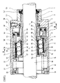
- FIG. 1 shows a braking and / or clamping device for the piston rod of a working cylinder, the clamping device essentially consisting of two sleeves arranged coaxially to one another and coaxially to the cylindrical body serving as the piston rod.
- the inner sleeve is slotted in its free end region and, on its side facing the outer sleeve, has tread parts for rolling bodies which run at an angle to the longitudinal axis of the cylindrical body.
- the outer sleeve has tread parts which have treads running obliquely to the longitudinal axis of the cylindrical body.
- the treads of the tread parts of the inner sleeve and the treads of the tread parts of the outer sleeve run parallel to one another.
- a cylindrical ring (1) is connected via a thread (2) to a cylindrical element designed as a first sleeve (3) for receiving and guiding a cylindrical body serving as a piston rod (16).
- the first sleeve (3) and the cylindrical body are arranged coaxially to one another.
- the first sleeve (3) has slots in its free end area running in the direction of its longitudinal axis.
- the sections of the first sleeve (3) formed by the slots and serving as clamping elements (24 or 43) can be moved essentially radially to the cylindrical body (16) and have groove-like grooves in their outer lateral surface parallel to the longitudinal axis of the first sleeve (3) Recesses (54 or 55) each for a tread part (23 or 41) having a tread (25 or 42) running obliquely to the longitudinal axis of the cylindrical body (16).
- the depth of the groove-like recesses (54 and 55) is dimensioned such that the mutually facing end faces (22 and 30) or (39 and 44) of these groove-like recesses (54 and 55) are a little above the tread parts (23 or 41) protrude when the tread parts (23 or 41) rest with their side facing away from the tread on the groove base (29 or 40) of the associated clamping element (24 or 43).
- a second sleeve (9) Coaxial with the first sleeve (3) is a second sleeve (9) (cylindrical element) serving as an actuator. provided which surrounds the first sleeve (3) on part of its axial extent, namely on the tread part of the first sleeve (3) which has the clamping elements (24 and 43).
- the actuator (second sleeve 9) is displaceable relative to the cylindrical body (piston rod 16) in the direction of its longitudinal axis.
- the second sleeve (9) has in its inner wall facing the outer surface of the first sleeve (3) a plurality of groove-like recesses (56 and 57) running in the direction of the longitudinal axis of the second sleeve (9), which correspond to the groove-like recesses (54 and 55) the first sleeve (3) are opposite.
- Each of the groove-like recesses (56 and 57) of the second sleeve (9) serves to receive a respective tread part (11 or 34) which has a tread (12 or 33) which runs obliquely to the longitudinal axis of the cylindrical body (16).
- the slope of the slopes of the tread parts (23 and 41) of the first sleeve (3) and the slope of the slopes of the tread parts (11 and 34) of the second sleeve (9) run differently, so that the treads (25th or 42) of the tread parts (23 or 41) of the first sleeve (3) run parallel to the treads (12 or 33) of the tread parts (11 or 34) of the second sleeve (9).
- the depth of the groove-like recesses (56 and 57) is dimensioned such that the mutually facing end faces (14 and 8) and (31 and 38) of these groove-like recesses (56 and 57) are a bit above the tread parts (11 or 34) protrude when the tread parts (11 or 34) rest with their side facing away from the tread on the groove base (10 or 32) of the groove-like recesses (56 or 57) of the second sleeve (9).
- the groove-like recesses (54 and 55) between the first sleeve (3) and the groove-like recesses (56 and 57) of the second sleeve (9) delimited by the tread parts of the clamping elements and of the actuating member serve to receive in the direction of the longitudinal axis of the two sleeves (3 and 9) arranged running one behind the other, each with three rolling elements (26, 27, 28 and 35, 36, 37) designed as rollers, which on the running surfaces (25, 42) of the running surface parts 23, 41) of the clamping elements (24 and 43) and on the treads (12, 33) of the tread parts (11 and 34) of the second sleeve (9).
- the rolling elements (26, 27, 28 and 35, 36, 37) are arranged in such a way that their axes of rotation run transversely to the longitudinal axis of the sleeves (3 and 9).
- balls can of course also be provided.
- the two sleeves (3 and 9) are in one e.g. one-piece tubular housing (21, 4) is arranged, which consists of a head part (4) and a tubular body (21).
- the housing (21, 4) is connected to the cylindrical ring (1).
- a pressure medium connection (51) is provided in the head part (4) and is connected via a channel (50) to a pressure medium chamber (49) arranged in the housing (21, 4).
- the pressure medium chamber (49) is delimited on the one hand by the head part (4) and on the other hand by an annular piston (46) which is displaceably arranged in the tubular housing (21) and serves as an actuating device for the actuating member (9), the outer circumference of which is on a step of the inner wall of the tubular Housing (21) and with its inside on the outer circumferential surface of a tubular body (6), which is fastened to the head part (4) of the housing (21, 4) by means of a projection (5) and on one end face of the two sleeves ( 3 and 9) extends, is performed.
- the annular piston (46) has two sealing rings (48 and 47), a sealing ring (47) sealingly abutting the wall of the tubular housing (21) and a sealing ring (48) on the outer circumferential surface of the tubular body (6).
- the annular piston (46) which is displaceable in the direction of the longitudinal axis of the cylindrical body (piston rod 16) has a circumferential projection (45) which extends in the direction of one end face of the second sleeve (9) and bears against it.
- the stroke of the annular piston (46) is limited on the one hand by a circumferential projection (7) arranged at the free end of the tubular body (6) and extending radially outwards and on the other hand by the head part (4) of the housing (21, 4).
- a compression spring (15 or 20) is provided, which is supported with one end on a step of an annular part (17) which is at the end of the tubular Housing (21,4) is secured by means of a retaining ring (19) which is opposite the head part (4) of the housing (21, 4).
- the ring-shaped part (17) also serves to center a working cylinder flanged to the device.
- the locking ring (19) is mounted in a groove (18) in the inner wall of the housing (21, 4). With its other end, the compression spring (15 or 20) acts on the second sleeve (9) in the direction of the annular piston (46).
- the two springs (15 and 20) are shown to different degrees in the drawing.
- the stronger spring (20) is used when the spring force is used to clamp or brake and the clamping action or braking action is to be canceled by means of the ring piston (46).
- the weaker spring (15) is used when clamping or braking is effected with the ring piston (46) and the clamping or braking effect is to be canceled with the spring (15).
- the spring (15) is used finally as a restoring force.
- the depth of the recesses is dimensioned such that the mutually facing end faces (22, 30) or (39, 44) or (14, 8) or (31, 38) of the recesses (54, 55) or (56, 57) serve as stops for the rolling elements (26, 27, 28) or (35, 36, 37).
- the number of rows of rolling elements depends on the number of clamping elements.
- the piston rod (16) is led out of the cylindrical ring (1) in a sealed manner by means of a sealing ring (52) secured with a locking ring (53).
- FIG. 2 shows a section through the tubular housing (21, 4) with the piston rod (16) and the two sleeves (3 and 9) arranged coaxially to the latter.
- the four clamping elements of the first sleeve (three clamping elements (43, 64 and 61) are shown in the drawing are formed in that the free end region of the first sleeve (3) is provided with slots (62, 63) running in the longitudinal direction.
- the recesses for the tread parts (34 and 41) or (65 and 66) or (58 and 60) incorporated in the outer circumferential surface of the first sleeve (3) and in the inner wall of the second sleeve (9) surrounding it.
- the recesses are arranged opposite one another so that the rolling elements (36, 67 and 59) are guided in them.
- the rolling bodies (36, 67 and 59) designed as rollers are arranged in such a way that their longitudinal axis runs transversely to the longitudinal axis of the cylindrical body (16) serving as a piston rod.
- the piston rod (16) is extended to the right out of the cylinder by the working piston. During this process, the clamping device is in the release position. If the working piston and thus also the piston rod (16) are to be locked in a desired position, the pressure medium connection (51) and the channel (50) into the pressure and connection in the configuration of the braking and / or clamping device according to the lower part of the drawing pressure medium chamber (49) bounded by the annular piston (46).
- the rolling elements (26, 27, 28) are moved to the left in the direction of the free end of the first sleeve (3) serving as a carrier for the clamping elements (24).
- the inclined treads (12 and 25) of the two tread parts (11 and 23) endeavor to approach each other, which would reduce the distance between these two parts.
- the rolling elements (26, 27, 28) are arranged between the running surfaces (12 and 25), the distance between the running surfaces remains the same.
- the outer sleeve (9) is a closed, rigid, ring-shaped body, the rolling elements cannot deflect outwards. They therefore transfer the force exerted on them by the outer sleeve (9) to the clamping elements (24), as a result of which they are pressed against the outer surface of the piston rod (16).
- the clamping elements (24) arranged on the inner sleeve (3) are now clamped to the piston rod (16).
- the pressure medium chamber (49) delimited by the annular piston (46) is vented.
- the compression spring (15) moves the second sleeve (9) and thus also the ring piston (46) to the right, in the direction of the head part (4) of the housing (21, 4).
- the rolling elements (26, 27, 28) roll on the inclined but parallel running surfaces (12) or (25) of the tread parts (11) or (23) of the clamping elements (24) or the second sleeve ( 9) to the right, and the clamping elements (24) detach from the piston rod (16).
- the actuator is shown in the brake release position, the annular piston (46) abutting the stop (7) of the tubular body (6).
- the pressure in the pressure medium chamber (49) is reduced via a valve device (not shown).
- the second sleeve (9) is displaced towards the right in the direction of the head part (4) of the housing (21, 4).
- the tread parts (41) and (34) having the inclined treads (42) and (33) in the nutar term recesses (55) of the clamping elements (43) and in the groove-like recesses (57) of the second sleeve (9) rotated through 180 ° into these recesses, so that the clamping elements (43) associated tread parts one from the left to slope and the tread parts (34) assigned to the outer sleeve (9) have a slope from left to right, the treads (42) of the tread parts (41) assigned to the clamping elements (43) and the treads ( 33) of the tread parts (34) associated with the second sleeve (9) endeavors to approach each other.
- the rolling bodies (35, 36, 37) arranged between the opposing treads (42 and 33) prevent these treads (42 and 33) from approaching.
- the rolling elements (35, 36, 37) yield in the direction of the clamping elements (43) and thereby cause the clamping elements (43) to be pressed against the cylindrical body (16) serving as the piston rod.
- the clamping elements (43) and the cylindrical body (16) serving as a piston rod are braced against one another.
- pressure medium is introduced into the pressure medium chamber (49).
- the pressure building up in the pressure medium chamber (49) displaces the annular piston (46) and thus also the second sleeve (9) against the force of the spring (20) to the left in the direction of the annular body (17). Due to the friction between the running surfaces (33 and 42) and the rolling elements (35, 36 and 37), the rolling elements (35, 36, 37) roll on the running surfaces (33 and 42) until the rolling element (35) stops (39) comes to the plant.
- tread parts (34 or 41) and (11 or 23) which have the treads (33, 42) or (12, 25) can be inserted into the groove-like recesses, but they can also be pressed into them with slight pretensioning be or be connected by means of plug, snap or other connecting means with the clamping elements (24 and 43) or with the outer sleeve (9).
- the tread parts on the clamping elements and on the outer sleeve which have the treads for the rolling elements, can be designed such that, as shown in the drawing, both the tread parts arranged on the clamping elements and on the outer sleeve have a slope or have a slope, but they can also be designed such that only the tread parts provided on the clamping elements or only the tread parts arranged on the outer sleeve have an incline or a slope.
- This design and arrangement allows, seen in the axial direction, to arrange several rolling elements with the same diameter one behind the other.
- the braking or clamping action between the clamping elements and the cylindrical body designed as a piston rod is achieved in that, when there is a relative movement between the outer sleeve and the inner sleeve having the clamping elements in the direction of their longitudinal axis, the tread parts having the treads strive for theirs To reduce the distance from each other (the area of the one tread part with the larger cross section reaches the area with the larger cross section of the other opposite tread part). However, due to the rolling elements between the opposing tread parts, the distance between these tread parts is kept constant.
- the resiliently held or formed clamping element or the resiliently held or formed clamping elements have to evade relative movement between the outer rigid sleeve and the sleeve carrying the clamping elements in the direction of the cylindrical body serving as the piston rod.
- the sections serving as clamping elements can be pressed against the inner wall of the cylinder by an element guided in the second sleeve, for example a piston, over the inclined running surfaces and the rolling bodies interacting with them.
- This embodiment is particularly suitable for rodless working cylinders in which the working piston is intended to be fixable for positioning in predeterminable positions.
- the sleeve serving as the actuating element can be brought into a position both by means of the annular piston (46) and by means of the spring (20), in which the clamping elements become effective.
- the clamping elements become effective.
- only a rotation of the inclined running surfaces having surface parts 180 0 is required.
- the inner sleeve (3) is secured against rotation by four flats (68, 69, 70), as shown in Fig.2.
- the flats (68, 69, 70) are connected to corresponding flats of the housing.
- Elements (71 and 72) made of an elastic material can be provided in the slots (62 and 63), e.g. can consist of cylindrical rubber or plastic pieces, as shown in Fig.2. These elements (71, 72) push the clamping elements (43, 61, 64 apart), which causes the clamping to be released easily.
Landscapes
- Engineering & Computer Science (AREA)
- General Engineering & Computer Science (AREA)
- Mechanical Engineering (AREA)
- Physics & Mathematics (AREA)
- Fluid Mechanics (AREA)
- Braking Arrangements (AREA)
- Clamps And Clips (AREA)
- Actuator (AREA)
Claims (19)
caractérisée par les points suivants :
Applications Claiming Priority (2)
| Application Number | Priority Date | Filing Date | Title |
|---|---|---|---|
| DE3931014A DE3931014A1 (de) | 1989-09-16 | 1989-09-16 | Brems- oder/und klemmeinrichtung |
| DE3931014 | 1989-09-16 |
Publications (3)
| Publication Number | Publication Date |
|---|---|
| EP0418507A1 EP0418507A1 (fr) | 1991-03-27 |
| EP0418507B1 true EP0418507B1 (fr) | 1993-04-28 |
| EP0418507B2 EP0418507B2 (fr) | 1997-01-08 |
Family
ID=6389602
Family Applications (1)
| Application Number | Title | Priority Date | Filing Date |
|---|---|---|---|
| EP90114246A Expired - Lifetime EP0418507B2 (fr) | 1989-09-16 | 1990-07-25 | Dispositif de freinage et/ou de serrage |
Country Status (4)
| Country | Link |
|---|---|
| US (1) | US5115889A (fr) |
| EP (1) | EP0418507B2 (fr) |
| JP (1) | JPH03129134A (fr) |
| DE (2) | DE3931014A1 (fr) |
Families Citing this family (23)
| Publication number | Priority date | Publication date | Assignee | Title |
|---|---|---|---|---|
| JPH0749050Y2 (ja) * | 1991-03-01 | 1995-11-13 | エスエムシー株式会社 | 流体圧シリンダのロック装置 |
| DE4217164C2 (de) * | 1992-05-23 | 2002-11-21 | Bosch Gmbh Robert | Arbeitszylinder mit Brems- oder/und Klemmeinrichtung |
| DE19631427A1 (de) * | 1996-08-03 | 1998-02-05 | Guenter Dr Ing Frank | Klemmverbindung, insbesondere Welle-Nabe-Verbindung |
| US6009981A (en) * | 1996-09-17 | 2000-01-04 | Wolfe; William V. | Shaft locking or braking device for linear motion systems |
| IT1295302B1 (it) * | 1997-10-09 | 1999-05-04 | Tecnofluid Eng Srl | Dispositivo a pistoni per il bloccaggio in posizioni di elementi lineari mobili in traslazione |
| JP3856934B2 (ja) * | 1998-01-27 | 2006-12-13 | Smc株式会社 | ロック機構付き流体圧シリンダ |
| US6152268A (en) * | 1998-12-21 | 2000-11-28 | Advanced Machine & Engineering Co. | Rod clamp apparatus |
| DE10127664C1 (de) * | 2001-06-07 | 2003-04-17 | Kendrion Binder Magnete Gmbh | Elektromagnetisch betätigbare Bremsvorrichtung |
| DE10140561A1 (de) * | 2001-08-17 | 2003-02-27 | Ina Schaeffler Kg | Klemmgesperre |
| US6412606B1 (en) * | 2001-10-03 | 2002-07-02 | Chun-Liang Wu | Damper/positioning structure |
| JP4261235B2 (ja) * | 2003-04-01 | 2009-04-30 | 株式会社コガネイ | 流体圧シリンダ |
| US7131518B2 (en) * | 2003-11-14 | 2006-11-07 | Nexen Group, Inc. | Motion control apparatus with backlash reduction |
| JP4683929B2 (ja) * | 2004-02-25 | 2011-05-18 | 株式会社パボット技研 | 直線移動体のロック装置 |
| US7594565B1 (en) | 2004-05-06 | 2009-09-29 | Adams Jr Robert Curtis | Rod brake |
| DE102005016723A1 (de) * | 2005-04-11 | 2006-10-12 | Zimmer, Günther | Brems- und/oder Klemmvorrichtung mit wälzgelagertem Keilgetriebe |
| WO2006108197A1 (fr) * | 2005-04-11 | 2006-10-19 | Grigoryan, Emil | Roue spirale |
| JP5059686B2 (ja) | 2008-05-22 | 2012-10-24 | Juki株式会社 | 表面実装装置 |
| US8087845B2 (en) * | 2008-05-22 | 2012-01-03 | GM Global Technology Operations LLC | Integrated locking assembly for reconfigurable end-effectors |
| US8702340B2 (en) * | 2010-01-27 | 2014-04-22 | GM Global Technology Operations LLC | Integrated linear and rotary locking device |
| ITMN20130010A1 (it) * | 2013-10-07 | 2015-04-08 | Erre Di S R L | Bloccastelo. |
| KR101512471B1 (ko) * | 2014-09-11 | 2015-04-16 | 한국뉴매틱(주) | 록-블록을 이용한 로드부재 록킹장치 |
| DE102020002706A1 (de) * | 2020-05-06 | 2021-11-11 | Günther Zimmer | Ringklemmelement mit Vielkeilgetriebe |
| CN115507134A (zh) * | 2022-09-26 | 2022-12-23 | 浙江大学 | 一种光面圆柱气动锁紧装置 |
Family Cites Families (17)
| Publication number | Priority date | Publication date | Assignee | Title |
|---|---|---|---|---|
| DE660546C (de) * | 1935-06-18 | 1938-05-28 | Wilhelm Stieber Dr Ing | Loesbare Klemmverbindung zur Verbindung zweier mit Gleitflaechen aufeinandersitzender Koerper |
| FR988810A (fr) * | 1948-06-29 | 1951-08-31 | Atlas Stone Company Ltd | Dispositif avec cage à billes de blocage pour enserrer une tige ou un fil métallique |
| US2620813A (en) * | 1950-12-22 | 1952-12-09 | Chloride Electrical Storage Co | Selector mechanism |
| US2815736A (en) * | 1955-09-19 | 1957-12-10 | Clarence E Wright | Safety lock for fluid-pressure actuator |
| US3019502A (en) * | 1958-07-23 | 1962-02-06 | Henry J Frost | Locking device for oil well drill rods or pipes |
| FR1540210A (fr) * | 1966-10-26 | 1968-09-20 | Westinghouse Bremsen Apparate | Dispositif de desserrage pour cylindres de freins à ressort de réserve d'énergie, notamment pour véhicules |
| FR2057297A5 (fr) * | 1969-08-11 | 1971-05-21 | Pont A Mousson | |
| US3762512A (en) * | 1971-10-29 | 1973-10-02 | Us Elevator Corp | Elevator rail grab safety apparatus |
| US3951238A (en) * | 1974-12-16 | 1976-04-20 | Tyee Aircarft, Inc. | Linear motion arresting device |
| US4030579A (en) * | 1975-03-26 | 1977-06-21 | Picker X-Ray Mfg. Limited | Lineal lock for X-ray apparatus |
| FR2346588A1 (fr) * | 1975-10-20 | 1977-10-28 | Pradon Jacques | Pince de serrage |
| DE2616973C3 (de) * | 1976-04-17 | 1981-02-19 | Wabco Fahrzeugbremsen Gmbh, 3000 Hannover | Pneumatischer Arbeitszylinder zur Betätigung und stufenlosen Arretierung von Stellgliedern |
| DE3307644A1 (de) * | 1983-03-04 | 1984-09-06 | Klement, Klaus-D., 5170 Jülich | Druckmittelbetaetiger arbeitszylinder mit verriegelung in beliebiger stellungen |
| DE3319042A1 (de) * | 1983-05-26 | 1984-11-29 | Wabco Westinghouse Steuerungstechnik GmbH & Co, 3000 Hannover | Brems- oder/und klemmeinrichtung |
| DE8612933U1 (de) * | 1986-05-13 | 1987-01-08 | Overbeck GmbH & Co, 2800 Bremen | Vorrichtung zum Abstoppen einer Achse od. dgl. |
| CH663826A5 (de) * | 1987-02-26 | 1988-01-15 | Bieri Ag Liebefeld H | Druckfluid beaufschlagbare, verriegelbare spannzylinder-kolbeneinheit. |
| GB8814699D0 (en) * | 1988-06-21 | 1988-07-27 | Cooper Ind Inc | Emergency suspension system for drill casings |
-
1989
- 1989-09-16 DE DE3931014A patent/DE3931014A1/de not_active Withdrawn
-
1990
- 1990-07-25 DE DE9090114246T patent/DE59001302D1/de not_active Expired - Fee Related
- 1990-07-25 EP EP90114246A patent/EP0418507B2/fr not_active Expired - Lifetime
- 1990-09-12 JP JP2240210A patent/JPH03129134A/ja active Pending
- 1990-09-13 US US07/581,745 patent/US5115889A/en not_active Expired - Fee Related
Also Published As
| Publication number | Publication date |
|---|---|
| JPH03129134A (ja) | 1991-06-03 |
| DE3931014A1 (de) | 1991-03-28 |
| EP0418507B2 (fr) | 1997-01-08 |
| EP0418507A1 (fr) | 1991-03-27 |
| US5115889A (en) | 1992-05-26 |
| DE59001302D1 (de) | 1993-06-03 |
Similar Documents
| Publication | Publication Date | Title |
|---|---|---|
| EP0418507B1 (fr) | Dispositif de freinage et/ou de serrage | |
| DE102005000885B4 (de) | Stellglied | |
| DE2924707C2 (fr) | ||
| DE3319042A1 (de) | Brems- oder/und klemmeinrichtung | |
| EP0735944A1 (fr) | Dispositif de fermeture d'un moule pour machine a mouler par injection | |
| WO1998032565A2 (fr) | Dispositif de retenue, notamment pour une piece a usiner | |
| DE2548626B2 (de) | Verfahren und vorrichtung zum einsetzen einer o-ring-dichtung in die nut eines sitzringes | |
| DE1296013B (de) | Hydraulischer Druckkolben | |
| DE3732561C2 (fr) | ||
| DE3831459C2 (fr) | ||
| DE3046156A1 (de) | Betaetigungsvorrichtung fuer scheibenbremsen | |
| EP0436906A1 (fr) | Dispositif d'actionnement pour frein de véhicule, notamment frein à disque | |
| DE3234003C1 (de) | Verriegelungsvorrichtungen fuer Werkzeuge mit teleskopartig verschiebbaren Teilen | |
| DE2437705A1 (de) | Vorrichtung zur abdichtung eines gelenks | |
| DE2403173B2 (de) | Doppelgleitringdichtung | |
| DE3717616A1 (de) | Sicherheits-anschlussflansch fuer ein robotergefuehrtes werkzeug, insbesondere elektrisches schweisswerkzeug | |
| DE19906798A1 (de) | Radialkolbenbremse | |
| EP0568858B1 (fr) | Dispositif de verrouillage d'un piston commandé par pression, en particulier pour la commande d'une barre antirenversement d'un véhicule | |
| DE2655284A1 (de) | Pneumatisch oder hydraulisch und einseitig oder doppelt beaufschlagbare kolben-zylinder-vorrichtung | |
| DE3047254A1 (de) | Differenzdruckfuehler, insbesondere fuer fehler-meldeeinrichtungen an hydraulischen bremskreisen in kraftfahrzeugen | |
| WO1998006519A1 (fr) | Expanseur a dispositif de retour | |
| DE8812882U1 (de) | Druckluftzylinder mit Endlageverriegelung, insbesondere zur Betätigung von Rauchabzugsklappen | |
| DE60106534T2 (de) | Vorrichtung und einheit für die verriegelung der kolbenstange eines linearantriebes | |
| DE2062097A1 (de) | Honwerkzeug | |
| EP0771615A1 (fr) | Appareil de sertissage pour sertissage radial de connexions de tubes |
Legal Events
| Date | Code | Title | Description |
|---|---|---|---|
| PUAI | Public reference made under article 153(3) epc to a published international application that has entered the european phase |
Free format text: ORIGINAL CODE: 0009012 |
|
| AK | Designated contracting states |
Kind code of ref document: A1 Designated state(s): DE FR GB IT |
|
| 17P | Request for examination filed |
Effective date: 19910514 |
|
| 17Q | First examination report despatched |
Effective date: 19921016 |
|
| GRAA | (expected) grant |
Free format text: ORIGINAL CODE: 0009210 |
|
| AK | Designated contracting states |
Kind code of ref document: B1 Designated state(s): DE FR GB IT |
|
| PG25 | Lapsed in a contracting state [announced via postgrant information from national office to epo] |
Ref country code: IT Free format text: LAPSE BECAUSE OF FAILURE TO SUBMIT A TRANSLATION OF THE DESCRIPTION OR TO PAY THE FEE WITHIN THE PRESCRIBED TIME-LIMIT;WARNING: LAPSES OF ITALIAN PATENTS WITH EFFECTIVE DATE BEFORE 2007 MAY HAVE OCCURRED AT ANY TIME BEFORE 2007. THE CORRECT EFFECTIVE DATE MAY BE DIFFERENT FROM THE ONE RECORDED. Effective date: 19930428 Ref country code: FR Effective date: 19930428 Ref country code: GB Effective date: 19930428 |
|
| REF | Corresponds to: |
Ref document number: 59001302 Country of ref document: DE Date of ref document: 19930603 |
|
| EN | Fr: translation not filed | ||
| GBV | Gb: ep patent (uk) treated as always having been void in accordance with gb section 77(7)/1977 [no translation filed] |
Effective date: 19930428 |
|
| PLBI | Opposition filed |
Free format text: ORIGINAL CODE: 0009260 |
|
| 26 | Opposition filed |
Opponent name: FESTO KG Effective date: 19940110 |
|
| PLAW | Interlocutory decision in opposition |
Free format text: ORIGINAL CODE: EPIDOS IDOP |
|
| PLAW | Interlocutory decision in opposition |
Free format text: ORIGINAL CODE: EPIDOS IDOP |
|
| PUAH | Patent maintained in amended form |
Free format text: ORIGINAL CODE: 0009272 |
|
| STAA | Information on the status of an ep patent application or granted ep patent |
Free format text: STATUS: PATENT MAINTAINED AS AMENDED |
|
| 27A | Patent maintained in amended form |
Effective date: 19970108 |
|
| AK | Designated contracting states |
Kind code of ref document: B2 Designated state(s): DE FR GB IT |
|
| EN | Fr: translation not filed | ||
| PGFP | Annual fee paid to national office [announced via postgrant information from national office to epo] |
Ref country code: DE Payment date: 20060714 Year of fee payment: 17 |
|
| PG25 | Lapsed in a contracting state [announced via postgrant information from national office to epo] |
Ref country code: DE Free format text: LAPSE BECAUSE OF NON-PAYMENT OF DUE FEES Effective date: 20080201 |