EP0416227A1 - Transmission pour véhicule automobile - Google Patents
Transmission pour véhicule automobile Download PDFInfo
- Publication number
- EP0416227A1 EP0416227A1 EP90111928A EP90111928A EP0416227A1 EP 0416227 A1 EP0416227 A1 EP 0416227A1 EP 90111928 A EP90111928 A EP 90111928A EP 90111928 A EP90111928 A EP 90111928A EP 0416227 A1 EP0416227 A1 EP 0416227A1
- Authority
- EP
- European Patent Office
- Prior art keywords
- gear
- selector lever
- motor vehicle
- vehicle transmission
- display
- Prior art date
- Legal status (The legal status is an assumption and is not a legal conclusion. Google has not performed a legal analysis and makes no representation as to the accuracy of the status listed.)
- Granted
Links
Images


Classifications
-
- F—MECHANICAL ENGINEERING; LIGHTING; HEATING; WEAPONS; BLASTING
- F16—ENGINEERING ELEMENTS AND UNITS; GENERAL MEASURES FOR PRODUCING AND MAINTAINING EFFECTIVE FUNCTIONING OF MACHINES OR INSTALLATIONS; THERMAL INSULATION IN GENERAL
- F16H—GEARING
- F16H59/00—Control inputs to control units of change-speed-, or reversing-gearings for conveying rotary motion
- F16H59/02—Selector apparatus
- F16H59/0204—Selector apparatus for automatic transmissions with means for range selection and manual shifting, e.g. range selector with tiptronic
-
- F—MECHANICAL ENGINEERING; LIGHTING; HEATING; WEAPONS; BLASTING
- F16—ENGINEERING ELEMENTS AND UNITS; GENERAL MEASURES FOR PRODUCING AND MAINTAINING EFFECTIVE FUNCTIONING OF MACHINES OR INSTALLATIONS; THERMAL INSULATION IN GENERAL
- F16H—GEARING
- F16H63/00—Control outputs from the control unit to change-speed- or reversing-gearings for conveying rotary motion or to other devices than the final output mechanism
- F16H63/40—Control outputs from the control unit to change-speed- or reversing-gearings for conveying rotary motion or to other devices than the final output mechanism comprising signals other than signals for actuating the final output mechanisms
- F16H63/42—Ratio indicator devices
-
- F—MECHANICAL ENGINEERING; LIGHTING; HEATING; WEAPONS; BLASTING
- F16—ENGINEERING ELEMENTS AND UNITS; GENERAL MEASURES FOR PRODUCING AND MAINTAINING EFFECTIVE FUNCTIONING OF MACHINES OR INSTALLATIONS; THERMAL INSULATION IN GENERAL
- F16H—GEARING
- F16H59/00—Control inputs to control units of change-speed-, or reversing-gearings for conveying rotary motion
- F16H2059/006—Overriding automatic control
-
- F—MECHANICAL ENGINEERING; LIGHTING; HEATING; WEAPONS; BLASTING
- F16—ENGINEERING ELEMENTS AND UNITS; GENERAL MEASURES FOR PRODUCING AND MAINTAINING EFFECTIVE FUNCTIONING OF MACHINES OR INSTALLATIONS; THERMAL INSULATION IN GENERAL
- F16H—GEARING
- F16H63/00—Control outputs from the control unit to change-speed- or reversing-gearings for conveying rotary motion or to other devices than the final output mechanism
- F16H63/40—Control outputs from the control unit to change-speed- or reversing-gearings for conveying rotary motion or to other devices than the final output mechanism comprising signals other than signals for actuating the final output mechanisms
- F16H63/42—Ratio indicator devices
- F16H2063/423—Range indicators for automatic transmissions, e.g. showing selected range or mode
-
- F—MECHANICAL ENGINEERING; LIGHTING; HEATING; WEAPONS; BLASTING
- F16—ENGINEERING ELEMENTS AND UNITS; GENERAL MEASURES FOR PRODUCING AND MAINTAINING EFFECTIVE FUNCTIONING OF MACHINES OR INSTALLATIONS; THERMAL INSULATION IN GENERAL
- F16H—GEARING
- F16H59/00—Control inputs to control units of change-speed-, or reversing-gearings for conveying rotary motion
- F16H59/02—Selector apparatus
- F16H59/08—Range selector apparatus
- F16H59/10—Range selector apparatus comprising levers
Definitions
- the invention relates to a motor vehicle transmission as described in the preamble of claim 1.
- the known transmission allows both automatic and manual shifting.
- the selector lever is designed as a coordinate switch and can therefore be operated in two mutually perpendicular movement levels.
- One actuation level is used for switching from automatic to manual shift mode, while in the perpendicular actuation level the gears can be engaged one after the other, regardless of whether automatic or manual shift mode is selected.
- the selected gear is shown on the instrument panel.
- DE-OS 37 17 675 also shows a motor vehicle transmission that allows automatic and manual shifting.
- two selector gates running approximately parallel to one another are provided for a selector lever of the transmission.
- One shift gate is reserved for automatic operation.
- the individual gears can be shifted in step by step.
- the shift gates are simulated in a gear indicator.
- the individual speed steps of the automatic range are designated in the usual way with P, R, N, D, 3, 2, 1 and provided with light points.
- the light point assigned to it lights up according to the selected speed level. The driver can recognize the next switching options through the positions adjacent to the light point.
- the gear indicator provides a "+” and a "-" for upshifting and downshifting.
- the gear engaged appears in a display on the dashboard in manual mode.
- This type of display is primarily suitable for such transmissions in which the selector lever is guided in a conventional shift gate during automatic operation.
- a combination with a coordinate switch of the aforementioned type and with this type of gear display is not easily accomplished.
- the object of the invention is to further develop a generic motor vehicle transmission so that the selection of the selector lever is not restricted, and that the driver clearly and quickly recognizes the switching options available to him at each selected speed level.
- the image of the gear indicator changes as the gears are shifted.
- the driver recognizes the gear selected and at the same time the shifting options, which differ depending on the gear selected.
- the invention is particularly well suited for motor vehicle transmissions in which the selector lever is no longer mechanically connected to the transmission, but only serves as a shift command transmitter.
- the switching commands are processed by a central evaluation circuit.
- the evaluation circuit controls the actuators for switching the individual speed steps and also the gear display.
- the driver can tell the evaluation electronics via the corresponding actuation of the selector lever whether he wants automatic or manual switching. Depending on this, it will take into account different shifting characteristics and also control the gear display accordingly.
- the selector lever can be moved in the directions of a planar axis cross according to the previously known coordinate switch move. When viewed in the direction of travel, it can therefore be pushed forwards and backwards, to the left and to the right. It is designed so that it automatically returns to its central position after each operation.
- the gear indicator is modeled on the actuation directions. It is designed as a bar cross and has five display fields. At the center of the cross, it shows the gear currently in use. The individual switching options are included in the cross arms. If the evaluation circuit does not provide a switching option for a direction of movement, this display field remains empty.
- two actuation planes which run in the direction of travel and are arranged parallel to one another are provided for the selector lever. Another actuation plane runs perpendicular to this.
- the two parallel directions of movement are assigned to automatic and manual mode.
- the operating direction perpendicular to it allows the selector lever to be changed into these two shift gates.
- selected speed levels such as parking or neutral can be selected on this level.
- the selector lever automatically returns to its central position as long as it is within one Weggasse is moved. It is locked in the switching alleys themselves.
- the gear indicator is modeled on the shift lanes. It has two display bars running parallel to one another, on the outside of which further display fields are provided.
- Each display bar contains the drive stages assigned to it in full, i.e. the drive stages P, R, N, D, 3, 2, 1 for the automatic range and 1, 2, 3, 4, 5 for the manual shift range for a five-speed transmission.
- the associated display bar with the gear names moves with it. It shows the gear currently selected, as well as the resulting shift options due to its position in relation to the other display bar and the external display fields.
- a screen which is controlled by the central switching electronics is advantageously suitable for the gear display.
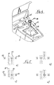
- a selector lever 1 sits on a center console 2 of a motor vehicle, not shown.
- the selector lever 1 is used to engage the individual driving stages of a motor vehicle transmission and, for this purpose, has electrical contacts at its lower end, which cannot be seen through a sleeve 3.
- the evaluation circuit is not the subject of the invention and is therefore not drawn and not explained in detail. It should only be mentioned that it can be easily constructed by a person skilled in the art and preferably contains a microcomputer. Your task is to control the actuators for the vehicle transmission, also not shown. On the other hand, it determines the display image of a gear indicator 4.
- the selector lever 1 can be moved in two mutually perpendicular actuation planes. This results in four directions, which are identified by corresponding arrows in FIG. 1.
- the actuating arrow in the direction of travel bears the reference number 5, that against the direction of travel bears the reference number 6, while the arrows to the left and to the right are designated by 7 and 8.
- the gear indicator 4 mentioned is also located on the center console 2, but moved towards the dashboard. In this way the driver can easily see it.
- the display image of the gear indicator 4 is simulated according to the directions of movement according to the arrows 5 to 7.
- FIG. 2 it is designed as a cross with five display fields.
- the central display field 9 in the center of the bar cross shows the currently selected gear.
- the display fields 10, 11, 12 and 13 are grouped in the cross arms. They correspond to the actuation directions of the selector lever 1 according to arrows 5, 6, 7 and 8 and indicate the switching options in relation to the selected speed level.
- the driving stage "D" is engaged in the case shown. This means that the transmission is in automatic mode.
- the remaining display fields show the driver which speed levels he could now choose.
- "R” for reverse gear appears on the left in display field 12. In this case, the driver would have to press selector lever 1 in the direction of arrow 7. The same applies to the other speed levels.
- "P” stands for park position, "N” for neutral and "M” for manual operation.
- FIG. 1 Various display images are shown in FIG.
- the double arrows are intended to indicate that the individual display images can be switched back and forth.
- the display image corresponding to FIG. 2 can be seen again under a). According to the double arrow, it can be transferred upwards into the display image b). This means a selector lever movement according to arrow 5 in FIG. 1.
- the driver can gradually shift up or down the individual gears one after the other. It can be clearly seen in the display images c1), c2) and f) that it is possible to switch back to automatic mode at any time or that the selector lever 1 can be moved into the neutral position "N".
- the vehicle slows down and the evaluation circuit on the gear indicator changes the corresponding shift patterns with decreasing speed and without operating the selector lever 1.
- FIG. 4 shows a second embodiment of the invention.
- the selector lever 1 can again be seen on the center console 2.
- the selector lever 1 is designed according to Figure 4 so that it at Actuations in the longitudinal direction of the vehicle return and return to their starting position. The same applies to the actuation in the direction of arrow 19.
- the selector lever is locked in both actuation levels in the longitudinal direction of the vehicle and also when actuated in the direction of arrow 18.
- gear indicator 20 on the console 2.
- the various display images of this gear indicator 20 appear in FIG. 5.
- the display images themselves are again labeled a) to e).
- the gear indicator 20 consists of two display bands 21, 22 aligned parallel to one another with the complete designation of all possible selection levels.
- the left display band 21 is assigned to the band switching operation and corresponds to the actuation directions of the arrows 14 and 16.
- the right display band 22 represents the automatic operation.
- the arrows 15 and 17 are assigned to it.
- two individual fields 23 and 24 each for the selection levels "N" and "R" appear on the gear display.
- the display bars 21 and 22 have shifted in this case, namely against each other and with respect to the fixed display fields 23 and 24.
- the gear indicator 20 is designed as a screen which is controlled by the evaluation electronics.
- the display image corresponds to the actuation directions of the selector lever 1 and is largely self-explanatory for the driver. He can clearly see in the respective display image in which directions he has to move the selector lever 1 in order to obtain the desired speed level.
- the gear indicator can be provided at any suitable location in the vehicle, for example as a further instrument in the dashboard. The same applies to the gear lever.
Applications Claiming Priority (2)
| Application Number | Priority Date | Filing Date | Title |
|---|---|---|---|
| DE3929268A DE3929268A1 (de) | 1989-09-02 | 1989-09-02 | Kraftfahrzeuggetriebe |
| DE3929268 | 1989-09-02 |
Publications (2)
| Publication Number | Publication Date |
|---|---|
| EP0416227A1 true EP0416227A1 (fr) | 1991-03-13 |
| EP0416227B1 EP0416227B1 (fr) | 1992-12-16 |
Family
ID=6388555
Family Applications (1)
| Application Number | Title | Priority Date | Filing Date |
|---|---|---|---|
| EP19900111928 Expired - Lifetime EP0416227B1 (fr) | 1989-09-02 | 1990-06-23 | Transmission pour véhicule automobile |
Country Status (2)
| Country | Link |
|---|---|
| EP (1) | EP0416227B1 (fr) |
| DE (2) | DE3929268A1 (fr) |
Cited By (9)
| Publication number | Priority date | Publication date | Assignee | Title |
|---|---|---|---|---|
| FR2807716A1 (fr) * | 2000-04-17 | 2001-10-19 | Peugeot Citroen Automobiles Sa | Dispositif de changement de vitesse pour une boite de vitesses mecanique automatisee ou robotisee |
| EP1146257A3 (fr) * | 2000-04-14 | 2004-01-28 | Siemens Aktiengesellschaft | Dispositif de sélection de gamme de vitesse ou de vitesse pour transmission des véhicules automobiles |
| WO2003102449A3 (fr) * | 2002-05-28 | 2004-02-19 | Zf Lemfoerder Metallwaren Ag | Dispositif d'affichage optique appartenant a un systeme de levier de selection |
| DE102004024327A1 (de) * | 2004-05-15 | 2005-12-01 | Wolfgang Dr. Mergenthaler | Kombinatorischer Verteil- und Sequenzier-Algorithmus von Schweisspunkten zur Kollisionsfreien und taktzeitminimalen Steuerung von Schweisszellen |
| DE102005062298A1 (de) * | 2005-12-24 | 2007-06-28 | Dr.Ing.H.C. F. Porsche Ag | Schaltvorrichtung für ein Getriebe |
| WO2010112932A1 (fr) | 2009-04-03 | 2010-10-07 | Bentley Motors Limited | Sélecteur |
| EP1486703A3 (fr) * | 2003-06-10 | 2011-04-27 | Honda Motor Co., Ltd. | Dispositif produisant une force tactile pour véhicule |
| WO2015009826A3 (fr) * | 2013-07-18 | 2015-03-19 | Chrysler Group Llc | Sélecteur électronique de type levier pourvu d'une position de levier cachée |
| WO2020109385A1 (fr) * | 2018-11-30 | 2020-06-04 | Zf Friedrichshafen Ag | Dispositif permettant de sélectionner un mode de fonctionnement d'un véhicule automobile |
Families Citing this family (16)
| Publication number | Priority date | Publication date | Assignee | Title |
|---|---|---|---|---|
| DE4228982C1 (fr) * | 1992-08-31 | 1993-09-02 | Lemfoerder Metallwaren Ag, 49448 Lemfoerde, De | |
| DE4233938A1 (de) * | 1992-10-08 | 1994-04-14 | Bayerische Motoren Werke Ag | Schaltvorrichtung für ein durch ein elektronisches Steuergerät gesteuertes automatisches Gebtriebe eines Kraftfahrzeuges |
| DE4305903A1 (de) * | 1993-02-26 | 1994-09-01 | Bayerische Motoren Werke Ag | Schaltvorrichtung für ein automatisch schaltendes Kraftfahrzeuggetriebe |
| DE19529207C2 (de) * | 1995-08-09 | 2001-04-26 | Zf Lemfoerder Metallwaren Ag | Schaltstellungsanzeige |
| DE19714495A1 (de) * | 1997-04-08 | 1998-10-15 | Bayerische Motoren Werke Ag | Wähleinrichtung mit einer Anzeigeeinrichtung |
| DE19725231B4 (de) * | 1997-06-14 | 2008-11-13 | Volkswagen Ag | Getriebeganganzeige |
| DE19804640B4 (de) * | 1998-02-06 | 2007-11-22 | Bayerische Motoren Werke Ag | Kraftfahrzeug mit einem elektronisch gesteuerten Automatikgetriebe |
| DE19828039B4 (de) * | 1998-06-24 | 2006-10-12 | Siemens Ag | Bedienvorrichtung |
| DE19850685A1 (de) | 1998-11-03 | 2000-05-04 | Bayerische Motoren Werke Ag | Wähleinrichtung für ein automatisches Getriebe eines Kraftfahrzeugs |
| DE10105491B4 (de) * | 2001-02-07 | 2010-05-12 | Jopp Gmbh | Schaltvorrichtung für ein Getriebe |
| JP3792586B2 (ja) * | 2002-03-12 | 2006-07-05 | 本田技研工業株式会社 | 車両の変速操作装置 |
| DE102004047102B3 (de) * | 2004-09-29 | 2006-03-09 | Bayerische Motoren Werke Ag | Kraftfahrzeug mit einer elektronisch ansteuerbaren Parksperre und mit einer elektronisch ansteuerbaren Feststellbremse |
| DE102004047100B3 (de) * | 2004-09-29 | 2006-03-02 | Bayerische Motoren Werke Ag | Kraftfahrzeug mit einer Parksperre und mit einer Feststellbremse |
| DE102005046278B4 (de) * | 2004-09-29 | 2008-04-03 | Bayerische Motoren Werke Ag | Kraftfahrzeug mit einer elektronisch ansteuerbaren Parksperre und mit einer elektronisch ansteuerbaren Feststellbremse |
| DE202010007515U1 (de) | 2010-06-02 | 2010-09-02 | Leopold Kostal Gmbh & Co. Kg | Vorrichtung zur Betätigung einer Parksperre eines automatisiert betätigten Getriebes eines Kraftfahrzeugs |
| DE102011010705A1 (de) | 2011-02-09 | 2012-08-16 | Gm Global Technology Operations, Llc | Personenkraftfahrzeug ohne B-Säule |
Citations (8)
| Publication number | Priority date | Publication date | Assignee | Title |
|---|---|---|---|---|
| DE1964524A1 (de) * | 1968-12-31 | 1970-07-16 | Citroen Sa | Elektronische Steuervorrichtung fuer ein Getriebe mit abgestuften UEbersetzungsverhaeltnissen |
| US3985095A (en) * | 1975-01-09 | 1976-10-12 | General Motors Corporation | Gear shift indicator |
| DE3237509A1 (de) * | 1982-10-09 | 1984-04-12 | Wabco Westinghouse Fahrzeugbremsen GmbH, 3000 Hannover | Gangschaltung fuer ein fremdkraftbetaetigtes getriebe |
| DE3237517A1 (de) * | 1982-10-09 | 1984-04-12 | Wabco Westinghouse Fahrzeugbremsen GmbH, 3000 Hannover | Schaltanzeige fuer eine gangschaltung |
| DE3337930A1 (de) * | 1982-12-23 | 1984-07-05 | Zahnradfabrik Friedrichshafen Ag, 7990 Friedrichshafen | Waehlschalter in einer schaltsteuerung fuer automatgetriebe |
| DE3422262A1 (de) * | 1984-06-15 | 1985-12-19 | Audi AG, 8070 Ingolstadt | Schaltvorrichtung fuer ein automatisches getriebe |
| FR2600285A1 (fr) * | 1986-06-20 | 1987-12-24 | Renault | Dispositif de commande electromecanique de boite de vitesses automatique |
| DE3717675A1 (de) * | 1987-05-26 | 1988-12-08 | Bayerische Motoren Werke Ag | Kraftfahrzeug mit automatischem getriebe |
Family Cites Families (8)
| Publication number | Priority date | Publication date | Assignee | Title |
|---|---|---|---|---|
| DE734540C (de) * | 1937-05-15 | 1943-04-19 | Engrenages De Prec Procedes Ma | Umschaltvorrichtung fuer elektromagnetische Kraftfahrzeug-Wechselgetriebe |
| DE721350C (de) * | 1939-04-29 | 1942-06-06 | Miag Muehlenbau Und Ind Ag | Selbsttaetige Schaltung fuer Gangwechselgetriebe oder stufenlose Getriebe von Kraftfahrzeugen o. dgl. |
| DE812999C (de) * | 1950-05-13 | 1951-09-06 | Eugen Bauckhage | Anzeigevorrichtung fuer den eingeschalteten Gang bei Motorfahrzeugen |
| DE891661C (de) * | 1951-12-14 | 1953-10-01 | Daimler Benz Ag | Geschwindigkeitsanzeigevorrichtung fuer Kraftfahrzeuge |
| US2964964A (en) * | 1959-04-10 | 1960-12-20 | Gen Motors Corp | Control mechanism |
| DE1929359U (de) * | 1965-07-03 | 1965-12-16 | Franz Walter Wissmann | Kraftfahrzeug mit gangschaltung. |
| DE2507086A1 (de) * | 1975-02-19 | 1976-08-26 | Daimler Benz Ag | Ganganzeige fuer kraftfahrzeuge |
| DE3807881A1 (de) * | 1988-03-10 | 1989-09-21 | Porsche Ag | Schaltvorrichtung fuer ein automatikgetriebe eines kraftfahrzeugs |
-
1989
- 1989-09-02 DE DE3929268A patent/DE3929268A1/de not_active Withdrawn
-
1990
- 1990-06-23 DE DE9090111928T patent/DE59000604D1/de not_active Expired - Fee Related
- 1990-06-23 EP EP19900111928 patent/EP0416227B1/fr not_active Expired - Lifetime
Patent Citations (8)
| Publication number | Priority date | Publication date | Assignee | Title |
|---|---|---|---|---|
| DE1964524A1 (de) * | 1968-12-31 | 1970-07-16 | Citroen Sa | Elektronische Steuervorrichtung fuer ein Getriebe mit abgestuften UEbersetzungsverhaeltnissen |
| US3985095A (en) * | 1975-01-09 | 1976-10-12 | General Motors Corporation | Gear shift indicator |
| DE3237509A1 (de) * | 1982-10-09 | 1984-04-12 | Wabco Westinghouse Fahrzeugbremsen GmbH, 3000 Hannover | Gangschaltung fuer ein fremdkraftbetaetigtes getriebe |
| DE3237517A1 (de) * | 1982-10-09 | 1984-04-12 | Wabco Westinghouse Fahrzeugbremsen GmbH, 3000 Hannover | Schaltanzeige fuer eine gangschaltung |
| DE3337930A1 (de) * | 1982-12-23 | 1984-07-05 | Zahnradfabrik Friedrichshafen Ag, 7990 Friedrichshafen | Waehlschalter in einer schaltsteuerung fuer automatgetriebe |
| DE3422262A1 (de) * | 1984-06-15 | 1985-12-19 | Audi AG, 8070 Ingolstadt | Schaltvorrichtung fuer ein automatisches getriebe |
| FR2600285A1 (fr) * | 1986-06-20 | 1987-12-24 | Renault | Dispositif de commande electromecanique de boite de vitesses automatique |
| DE3717675A1 (de) * | 1987-05-26 | 1988-12-08 | Bayerische Motoren Werke Ag | Kraftfahrzeug mit automatischem getriebe |
Cited By (14)
| Publication number | Priority date | Publication date | Assignee | Title |
|---|---|---|---|---|
| EP1146257A3 (fr) * | 2000-04-14 | 2004-01-28 | Siemens Aktiengesellschaft | Dispositif de sélection de gamme de vitesse ou de vitesse pour transmission des véhicules automobiles |
| FR2807716A1 (fr) * | 2000-04-17 | 2001-10-19 | Peugeot Citroen Automobiles Sa | Dispositif de changement de vitesse pour une boite de vitesses mecanique automatisee ou robotisee |
| WO2003102449A3 (fr) * | 2002-05-28 | 2004-02-19 | Zf Lemfoerder Metallwaren Ag | Dispositif d'affichage optique appartenant a un systeme de levier de selection |
| US7167085B2 (en) | 2002-05-28 | 2007-01-23 | ZF Lemförder Metallwaren AG | Optical display device for a selector lever arrangement |
| EP1486703A3 (fr) * | 2003-06-10 | 2011-04-27 | Honda Motor Co., Ltd. | Dispositif produisant une force tactile pour véhicule |
| EP2390535A1 (fr) * | 2003-06-10 | 2011-11-30 | Honda Motor Co., Ltd. | Appareil pour générer une force tactile pour un véhicule |
| DE102004024327A1 (de) * | 2004-05-15 | 2005-12-01 | Wolfgang Dr. Mergenthaler | Kombinatorischer Verteil- und Sequenzier-Algorithmus von Schweisspunkten zur Kollisionsfreien und taktzeitminimalen Steuerung von Schweisszellen |
| US7878087B2 (en) | 2005-12-24 | 2011-02-01 | Dr Ing. H.C. F. Porsche Aktiengesellschaft | Selector device for a transmission |
| EP1801463A3 (fr) * | 2005-12-24 | 2008-06-18 | Dr. Ing. h.c. F. Porsche Aktiengesellschaft | Dispositif pour changer la vitesse pour une boîte de vitesses |
| DE102005062298A1 (de) * | 2005-12-24 | 2007-06-28 | Dr.Ing.H.C. F. Porsche Ag | Schaltvorrichtung für ein Getriebe |
| WO2010112932A1 (fr) | 2009-04-03 | 2010-10-07 | Bentley Motors Limited | Sélecteur |
| CN102365478A (zh) * | 2009-04-03 | 2012-02-29 | 英国宾利汽车有限公司 | 选择器 |
| WO2015009826A3 (fr) * | 2013-07-18 | 2015-03-19 | Chrysler Group Llc | Sélecteur électronique de type levier pourvu d'une position de levier cachée |
| WO2020109385A1 (fr) * | 2018-11-30 | 2020-06-04 | Zf Friedrichshafen Ag | Dispositif permettant de sélectionner un mode de fonctionnement d'un véhicule automobile |
Also Published As
| Publication number | Publication date |
|---|---|
| DE59000604D1 (de) | 1993-01-28 |
| EP0416227B1 (fr) | 1992-12-16 |
| DE3929268A1 (de) | 1991-03-07 |
Similar Documents
| Publication | Publication Date | Title |
|---|---|---|
| EP0416227B1 (fr) | Transmission pour véhicule automobile | |
| EP0870955B1 (fr) | Levier de changement de vitesse avec un dispositif de signalisation de position | |
| DE10206985B4 (de) | Getriebeschalteinrichtung | |
| EP1045172B1 (fr) | Dispositif de commande pour une boíte de vitesses automatique de véhicule automobile | |
| DE19706625B4 (de) | Fahrstufenschaltvorrichtung für ein Automatikgetriebe | |
| DE4005588C2 (de) | Schaltvorrichtung für ein automatisches Getriebe | |
| DE3717675C5 (de) | Schalteinrichtung für ein Kraftfahrzeug mit automatischem Getriebe | |
| DE3832971C2 (fr) | ||
| EP0108209A2 (fr) | Changement de vitesse pour transmission à commande par force séparée | |
| EP0999383A2 (fr) | Dispositif de changement de vitesse pour une transmission automatique d'une véhicule automobile | |
| EP1432934B1 (fr) | Emetteur de signaux concu pour regler les etats de fonctionnement d'un dispositif de commutation automatique | |
| DE102012215659A1 (de) | Elektronische Gangschaltung mit adaptiver Position | |
| EP0106789B1 (fr) | Indicateur pour changement de vitesse | |
| DE102005048875B4 (de) | Schalteinheit für ein elektronisch geschaltetes Getriebe eines Kraftfahrzeugs | |
| DE3337930C2 (de) | Wählschalter in einer Schaltsteuerung für Automatgetriebe | |
| DE3924318A1 (de) | Schaltung fuer ein kraftfahrzeuggetriebe | |
| DE19849076A1 (de) | Wähleinrichtung für ein automatisch geschaltetes Getriebe eines Kraftfahrzeugs | |
| DE3939030A1 (de) | Schaltstellungsanzeige fuer schalt- oder waehlhebel | |
| EP1081414B1 (fr) | Dispositif de changement de vitesses pour commander une transmission automatique de véhicule automobile | |
| DE10105491B4 (de) | Schaltvorrichtung für ein Getriebe | |
| EP0725233A2 (fr) | Sélecteur de vitesses pour boîte à vitesses | |
| EP0798493B1 (fr) | Dispositif de commande de boíte de vitesses | |
| DE19609585A1 (de) | Verfahren zum Steuern eines stufenlosen Getriebes sowie Vorrichtung hierzu | |
| EP4038295B1 (fr) | Système de boîte de vitesses et procédé de fonctionnement dudit type de de boîte de vitesses | |
| DE10000338A1 (de) | Vorrichtung zur Ermittlung des bei einem Kraftfahrzeug eingelegten Ganges |
Legal Events
| Date | Code | Title | Description |
|---|---|---|---|
| PUAI | Public reference made under article 153(3) epc to a published international application that has entered the european phase |
Free format text: ORIGINAL CODE: 0009012 |
|
| 17P | Request for examination filed |
Effective date: 19901221 |
|
| AK | Designated contracting states |
Kind code of ref document: A1 Designated state(s): DE FR GB IT |
|
| 17Q | First examination report despatched |
Effective date: 19920309 |
|
| GRAA | (expected) grant |
Free format text: ORIGINAL CODE: 0009210 |
|
| AK | Designated contracting states |
Kind code of ref document: B1 Designated state(s): DE FR GB IT |
|
| GBT | Gb: translation of ep patent filed (gb section 77(6)(a)/1977) |
Effective date: 19921217 |
|
| REF | Corresponds to: |
Ref document number: 59000604 Country of ref document: DE Date of ref document: 19930128 |
|
| ITF | It: translation for a ep patent filed |
Owner name: STUDIO JAUMANN |
|
| ET | Fr: translation filed | ||
| RAP4 | Party data changed (patent owner data changed or rights of a patent transferred) |
Owner name: BAYERISCHE MOTOREN WERKE AKTIENGESELLSCHAFT |
|
| PLBE | No opposition filed within time limit |
Free format text: ORIGINAL CODE: 0009261 |
|
| STAA | Information on the status of an ep patent application or granted ep patent |
Free format text: STATUS: NO OPPOSITION FILED WITHIN TIME LIMIT |
|
| 26N | No opposition filed | ||
| PGFP | Annual fee paid to national office [announced via postgrant information from national office to epo] |
Ref country code: DE Payment date: 19950526 Year of fee payment: 6 |
|
| PGFP | Annual fee paid to national office [announced via postgrant information from national office to epo] |
Ref country code: GB Payment date: 19950622 Year of fee payment: 6 |
|
| PGFP | Annual fee paid to national office [announced via postgrant information from national office to epo] |
Ref country code: FR Payment date: 19950630 Year of fee payment: 6 |
|
| PG25 | Lapsed in a contracting state [announced via postgrant information from national office to epo] |
Ref country code: GB Effective date: 19960623 |
|
| GBPC | Gb: european patent ceased through non-payment of renewal fee |
Effective date: 19960623 |
|
| PG25 | Lapsed in a contracting state [announced via postgrant information from national office to epo] |
Ref country code: FR Effective date: 19970228 |
|
| PG25 | Lapsed in a contracting state [announced via postgrant information from national office to epo] |
Ref country code: DE Effective date: 19970301 |
|
| REG | Reference to a national code |
Ref country code: FR Ref legal event code: ST |
|
| PG25 | Lapsed in a contracting state [announced via postgrant information from national office to epo] |
Ref country code: IT Free format text: LAPSE BECAUSE OF NON-PAYMENT OF DUE FEES;WARNING: LAPSES OF ITALIAN PATENTS WITH EFFECTIVE DATE BEFORE 2007 MAY HAVE OCCURRED AT ANY TIME BEFORE 2007. THE CORRECT EFFECTIVE DATE MAY BE DIFFERENT FROM THE ONE RECORDED. Effective date: 20050623 |